Ruckus Wireless ZoneFlex 7782 Installation Manual
Dual band 802.11n outdoor access point
Hide thumbs
Also See for ZoneFlex 7782:
- Mounting manual (4 pages) ,
- User manual (149 pages) ,
- User manual (148 pages)

Related Manuals for Ruckus Wireless ZoneFlex 7782


Summary of Contents for Ruckus Wireless ZoneFlex 7782
-
Page 1: Installation Guide
™ Ruckus Wireless ™ ZoneFlex 7782 Dual Band 802.11n Outdoor Access Point Installation Guide Part Number 800-70387-001 Rev B Published December 2012 www.ruckuswireless.com... -
Page 3: Table Of Contents
Contents About this Installation Guide ..........1 Using this Installation Guide . - Page 4 Configuring the AP for Management by FlexMaster or for Standalone Operation . . 20 Configuring the Administrative Computer ........20 Connecting the AP to the Administrative Computer .
- Page 5 Reading Related Documentation ......... . 64 Appendix A: Ruckus Wireless-Supplied and Customer-Ordered Parts ....65 Appendix B: Resetting the Access Point to Factory Default Settings .
-
Page 7: About This Installation Guide
Figure 1 shows the main steps, and Table 1 includes the substeps. Figure 1. Adding a 7782 AP to an existing Ruckus Wireless network flowchart Planning the Installation Preparing at the Depot and Sending to the Field Installing the AP... - Page 8 About this Installation Guide Using this Installation Guide Table 1. Adding a 7782 AP to an Existing Ruckus Wireless network Section Heading Planning the 7782 Access Point Installation • 7782 AP Versions • AP Connectors and LEDs • Positioning the GPS Antenna •...
-
Page 9: Related Documentation
About this Installation Guide Related Documentation Related Documentation In addition to this guide, each Ruckus Wireless ZoneFlex 7782 802.11n Outdoor Access Point documentation set includes the following: User Guide: Provides detailed information on how to configure the Outdoor Access ■... -
Page 10: Planning The 7782 Access Point Installation
Planning the 7782 Access Point Installation 7782 AP Versions Planning the 7782 Access Point Installation Before installing the 7782, it is helpful to verify the version and to plan the AP installation: 7782 AP Versions ■ AP Connectors and LEDs ■... -
Page 11: 7782-S
Planning the 7782 Access Point Installation 7782 AP Versions Figure 3. 7782 Mesh elevation plane coverage, side view Excellent Excellent Reach Reach Excellent Reach 7782-S The 7782-S 120-Degree Sector (ordering part number 901-7782-xx51) is best deployed where internal-antenna horizontal beamforming can provide extended reach and throughput to a 120-degree coverage area. -
Page 12: 7782-N
Planning the 7782 Access Point Installation 7782 AP Versions 7782-N The 7782-N 30-Degree Narrow Sector (ordering part number 901-7782-xx61) is best deployed where internal-antenna narrow beamforming can provide exceptional coverage to a narrow sector, or can support extended reach in a point-to-point deployment. See Figure 5 for internal-antenna coverage patterns and see Figure 6... -
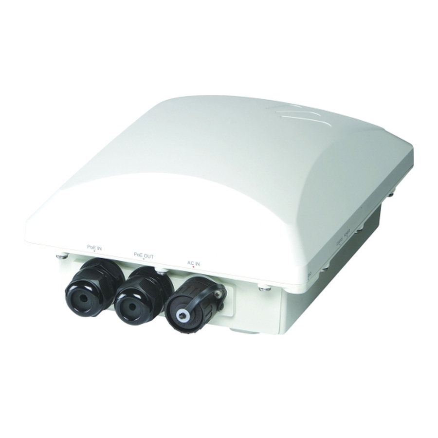
Page 13: Ap Connectors And Leds
Label Description PoE IN RJ45 data Supports 10/100/1000Mbps connections, connects to the network and connector receives 802.3at Power over Ethernet (PoE) from the Ruckus Wireless 60W PoE injector. (Refer to “Appendix A: Ruckus Wireless-Supplied and Customer-Ordered Parts” page 65 to order a Ruckus Wireless... - Page 14 Supports 10/100/1000Mbps connections and PoE out. If the AP is data connector powered using AC or the Ruckus Wireless PoE injector (ordered separately), then this port can supply 802.3af (15.4W) PoE to a connected PoE-capable device (for example, an IP-based surveillance camera).
-
Page 15: Positioning The Gps Antenna
Planning the 7782 Access Point Installation Positioning the GPS Antenna Positioning the GPS Antenna The 7782 Omni, 7782-S 120-Degree Sector, and 7782-N 30-Degree Narrow Sector APs all include an internal GPS antenna, while the 7782-E External Antenna AP can be equipped with a powered external GPS antenna. - Page 16 Planning the 7782 Access Point Installation Positioning the GPS Antenna Figure 9. 7782, 7782-S and 7782-N Dome-Down Mount GPS Antenna Position Figure 10. 7782, 7782-S and 7782-N Sector Mount GPS Antenna Position...
- Page 17 Planning the 7782 Access Point Installation Positioning the GPS Antenna Figure 11. 7782-E External GPS Antenna Position...
-
Page 18: Performing A Site Survey
Performing a Site Survey Perform a site survey to determine the optimal AP placement or maximum range, coverage, and network performance. Ruckus Wireless Support can supply Site Survey best practices information. The location and orientation that you choose for the AP play a critical role in the performance of your wireless network. -
Page 19: Planning The Physical Installation
AC installation. Note which components must be installed indoors and outdoors. Ruckus Wireless strongly recommends 80mm - 130mm (3”-5”) drip loops on any cables that are installed outdoors (for example, on an outdoor AP). -
Page 20: Deciding How To Power The Ap
The 7782 APs used in a mesh network generally use AC power. Power over Ethernet The customer orders a Ruckus Wireless PoE injector (part number 902-0180-XX00, where XX is the country code). Note the following: The AP may be powered by AC power or by PoE input using an 802.3af/at compliant ■... -
Page 21: Preparing The 7782 Access Point At The Depot And Shipping To The Field
4. Verify that all items listed in “Package Contents” “Mounting Kit Contents” included in the package. Check each item for damage. If any item is damaged or missing, notify your authorized Ruckus Wireless sales representative. NOTE: “Appendix A: Ruckus Wireless-Supplied and Customer-Ordered Parts” page 65 includes pictures and descriptions of these and other factory-orderable and customer-supplied parts. -
Page 22: Package Contents
One Mounting Kit (refer to “Mounting Kit Contents” for details) Mounting Kit Contents NOTE: “Appendix A: Ruckus Wireless-Supplied and Customer-Ordered Parts” page 65 includes pictures and descriptions of these and other factory-orderable and customer-supplied parts. The mounting kit includes the following: •... -
Page 23: Powering The Ap
Preparing the 7782 Access Point at the Depot and Shipping to the Field Powering the AP Powering the AP NOTE: You only need to connect one type of power source at this point, even if you are planning to use both PoE and AC power in your final deployment. Apply power to the AP and check the LED operation using one of these two methods: •... -
Page 24: Configuring The Ap For Management By Zonedirector
Preparing the 7782 Access Point at the Depot and Shipping to the Field Configuring the AP for Management by ZoneDirector Configuring the AP for Management by ZoneDirector 1. Collect required equipment and information: • One Cat5e or better Ethernet cable. •... - Page 25 Preparing the 7782 Access Point at the Depot and Shipping to the Field Configuring the AP for Management by ZoneDirector When the Status column shows Connected, this indicates that the AP has successfully registered with ZoneDirector. NOTE: If the ZoneDirector is set to Enable Mesh, it automatically assigns the 7782 AP as a Root AP.
-
Page 26: Configuring The Ap For Management By Flexmaster Or For Standalone Operation
Preparing the 7782 Access Point at the Depot and Shipping to the Field Configuring the AP for Management by FlexMaster or for Standalone Operation Configuring the AP for Management by FlexMaster or for Standalone Operation 1. Collect required equipment and information: •... - Page 27 Preparing the 7782 Access Point at the Depot and Shipping to the Field Configuring the AP for Management by FlexMaster or for Standalone Operation 4. Write down all of the currently active network settings. You will need this information later when you restore your computer to its current network configuration. 5.
-
Page 28: Connecting The Ap To The Administrative Computer
Preparing the 7782 Access Point at the Depot and Shipping to the Field Configuring the AP for Management by FlexMaster or for Standalone Operation Connecting the AP to the Administrative Computer 1. If you are powering the AP with PoE, then continue with Step 2. - Page 29 Preparing the 7782 Access Point at the Depot and Shipping to the Field Configuring the AP for Management by FlexMaster or for Standalone Operation 4. In User name, type super. 5. In Password, type sp-admin. 6. Click Login. The Web interface appears, displaying the Status > Device page. Continue with Configuring Common Wireless Settings.
-
Page 30: Configuring Common Wireless Settings
192.168.0.1 Default management IP address NOTE: ZoneFlex 7782 has one 2.4GHz radio and one 5GHz radio. The wireless settings for each radio need to be configured separately on the Web interface. To configure the 2.4GHz radio settings, click Configuration > Radio 2.4G. To configure the 5GHz radio settings, click Configuration >... - Page 31 AP uses only the radio channels allowed in your country or region. NOTE: The two radios on the ZoneFlex 7782 AP are always configured with the same country code setting. If you change the country code for Radio 2.4G, for example, the same change will be automatically...
-
Page 32: Configuring Wireless # Settings
4. Clear the SSID box, and then type a unique and descriptive name that you want to call this wireless network. For example, you can type Ruckus Wireless AP. This SSID is the name that helps users identify this wireless network in their wireless network connection application. -
Page 33: (Optional) Setting The Flexmaster Server Address
Preparing the 7782 Access Point at the Depot and Shipping to the Field Configuring the AP for Management by FlexMaster or for Standalone Operation If you are configuring the AP for management by FlexMaster, then continue with “(Optional) Setting the FlexMaster Server Address” page 27. - Page 34 Preparing the 7782 Access Point at the Depot and Shipping to the Field Configuring the AP for Management by FlexMaster or for Standalone Operation 3. Verify that the Auto option is selected. 4. In FlexMaster Server URL, type the URL of the FlexMaster server on the network. You can use either http or https to connect to the URL and include either the host name or IP address of the FlexMaster server in the URL.
-
Page 35: Verifying Ap Operation
Preparing the 7782 Access Point at the Depot and Shipping to the Field Verifying AP Operation Verifying AP Operation Ruckus Wireless recommends that you verify that the AP is operating correctly. NOTE: You can perform these verification tasks indoors. To verify that the AP is operating correctly, perform the following procedures: Connecting the AP to the Network ■... -
Page 36: Associating A Wireless Client With The Ap
Preparing the 7782 Access Point at the Depot and Shipping to the Field Verifying AP Operation 6. Connect the Ethernet cable from the Data In port on the PoE injector to your network’s router or switch. Continue with Associating a Wireless Client with the Associating a Wireless Client with the AP 1. -
Page 37: Disconnecting The Ap From The Power Source And The Network
Preparing the 7782 Access Point at the Depot and Shipping to the Field Verifying AP Operation Disconnecting the AP from the Power Source and the Network 1. Disconnect the AP from the power source (either from the PoE injector or AC power source). -
Page 38: Shipping The Ap To The Field
Preparing the 7782 Access Point at the Depot and Shipping to the Field Shipping the AP to the Field 4. Restore the computer’s network settings by typing the original IP address settings in the TCP/IP Properties dialog box. 5. In the TCP/IP Properties dialog box, click OK to close it. 6. -
Page 39: Installing The 7782 Access Point In The Field
Installing the 7782 Access Point in the Field Installation Components and Constraints Installing the 7782 Access Point in the Field Before installing the 7782 AP, Ruckus Wireless recommends that you first complete the procedures described in “Planning the 7782 Access Point Installation” page 4 “Preparing the 7782 Access Point at the Depot and Shipping to the Field”... - Page 40 Installing the 7782 Access Point in the Field Installation Components and Constraints PoE OUT supports 802.3af (15.4W output) loads when the AP is operating off AC input ■ power or when operating off the PoE input port using a high-power 60W PoE Injector. When AC powered and PoE is present, the AP draws power from the AC connection.
-
Page 41: Deploying The Access Point
Installing the 7782 Access Point in the Field Deploying the Access Point Deploying the Access Point In this section, you will mount the AP in its final mounting location. Perform the following: Connecting and Sealing the RJ-45 Cable ■ Connecting the AP to the Network ■... -
Page 42: Mounting The Access Point
■ Attaching the Hanger Mount to a Flat Surface WARNING: Ruckus Wireless strongly recommends that you wear eye protection before drilling holes on the mounting surface. 1. Place the hanger mount at the exact location on the mounting surface where you want to mount the AP. - Page 43 Installing the 7782 Access Point in the Field Mounting the Access Point 3. Remove the hanger mount or template from the mounting surface. 4. Follow the instructions in the customer-supplied wall anchor kit to attach the hanger mount to the flat surface. 5.
- Page 44 Installing the 7782 Access Point in the Field Mounting the Access Point Figure 19. Attaching the hanger mount to a vertical pole NOTE: Hanger mount shown attached horizontally to allow AP azimuth adjustments. Attach the hanger mount vertically to allow AP elevation adjustments.
-
Page 45: Assembling The Mounting Bracket And The Ap
Installing the 7782 Access Point in the Field Mounting the Access Point Assembling the Mounting Bracket and the AP 1. Place the mounting bracket onto the flat side of the AP so that the four screw holes on the bracket align with the four screw holes on the AP. Make sure that the longer ends of the mounting bracket point away from the AP PoE and AC IN connectors as shown Figure Figure 21. - Page 46 Installing the 7782 Access Point in the Field Mounting the Access Point 2. If required, then push one of the four 0.250-28 bolts with washers through the safety cable eye end as shown in Figure Figure 22. Attaching the safety cable and mounting bracket to the Access Point Access Mounting Point...
-
Page 47: Attaching The Ap And Mounting Bracket Assembly To The Hanger Mount
Installing the 7782 Access Point in the Field Mounting the Access Point Attaching the AP and Mounting Bracket Assembly to the Hanger Mount There are two ways to attach the 7782 AP and AP mounting bracket assembly to the mounting bracket, depending on the antenna directivity that you want to use. NOTE: The 7782-E AP can be mounted in any orientation, as long as the external GPS antenna can be mounted outdoors and pointed up or toward a mostly-unobstructed view of the sky. - Page 48 Installing the 7782 Access Point in the Field Mounting the Access Point 2. Insert an M8 hex bolt into the vertical screw hole on the mounting bracket. 3. Finger tighten the hex bolt until it passes through the screw hole on the hanger mount. 4.
- Page 49 Installing the 7782 Access Point in the Field Mounting the Access Point 2. Insert an M8 hex bolt into hole and finger tighten until the bolt passes through the screw hole on the hanger mount (Figure 25). Figure 25. Finger tighten the hex bolt until it passes through the hanger mount 3.
- Page 50 Installing the 7782 Access Point in the Field Mounting the Access Point Figure 26. Dome-down mounting 5. Adjust the tilt of the AP as required. NOTE: If the GPS feature is to be used on this AP, then make sure that the GPS antenna is mounted outdoors and pointed up or toward a mostly-unobstructed view of the sky as described in “Positioning the GPS Antenna”...
-
Page 51: Earth Grounding The Ap
Installing the 7782 Access Point in the Field Mounting the Access Point Earth Grounding the AP Be sure that earth grounding is available and that it meets local and national CAUTION: electrical codes. For additional lightning protection, use lightning rods and lightning arrestors. -
Page 52: Mounting External Antennas (7782-E Only)
Installing the 7782 Access Point in the Field Mounting External Antennas (7782-E Only) Mounting External Antennas (7782-E Only) Typical External Antenna Deployments ■ About the 7782-E Access Points ■ Mounting and Connecting 5GHz and 2.4GHz External Antennas ■ Mounting and Connecting an External GPS Antenna ■... -
Page 53: About The 7782-E Access Points
Installing the 7782 Access Point in the Field Mounting External Antennas (7782-E Only) About the 7782-E Access Points The 7782-E External Antenna access points have the connectors and LEDs described in Figure 7. The 7782-E APs also have seven more N-type connectors on the top cover for customer-supplied external antennas. - Page 54 Installing the 7782 Access Point in the Field Mounting External Antennas (7782-E Only) Table 6. Top-panel N-type connectors on the 7782-E access point Label Description 5GHz connectors: These 5GHz 50-ohm female connectors can be used with up to ANT 0, ANT 1 and three external antennas for operator-defined coverage areas and ANT 2 point-to-point deployments.
-
Page 55: Mounting And Connecting 5Ghz And 2.4Ghz External Antennas
Installing the 7782 Access Point in the Field Mounting External Antennas (7782-E Only) Mounting and Connecting 5GHz and 2.4GHz External Antennas You can connect up to three 5GHz external antennas and/or up to three 2.4GHz external antennas to the standard N-type female connectors on the 7782-E AP. WARNING: Only trained and qualified installers should be allowed to install, replace, or service this equipment. - Page 56 Installing the 7782 Access Point in the Field Mounting External Antennas (7782-E Only) NOTE: If you are connecting two 2.4GHz antennas to the AP, then use the ANT 0 and ANT 2 2.4GHz connectors. If you are connecting three 2.4GHz antennas to the AP, then use the all three 2.4GHz connectors.
-
Page 57: Mounting And Connecting An External Gps Antenna
Installing the 7782 Access Point in the Field Mounting External Antennas (7782-E Only) Mounting and Connecting an External GPS Antenna NOTE: If you are not connecting an external GPS antenna to the 7782-E AP, then make sure that the metal cap remains installed and securely fastened to protect the interface from elements, such as water and dirt. -
Page 58: Verifying Access Point Operation
Installing the 7782 Access Point in the Field Verifying Access Point Operation Verifying Access Point Operation After mounting the AP, Ruckus Wireless strongly recommends that you verify that the AP is operating correctly. To do this, you will need to do the following: Powering the AP ■... - Page 59 AC branch circuit should be protected with a Residual-Current Circuit Breaker (RCCB), also known as a Ground Fault Circuit Interrupter (GFCI), per National Electrical Code Article 210. Figure 30. Typical outdoor PoE installation components Indoor Outdoor ZoneFlex 7782 Outdoor AP Ground screw Drip loop Router...
- Page 60 Installing the 7782 Access Point in the Field Verifying Access Point Operation Powering the 7782 with AC 1. Collect required tools and supplies: • An outdoor-rated three-wire (1-2mm or 14-18AWG) AC cable that is long enough to connect the AP with the AC power source. •...
- Page 61 Installing the 7782 Access Point in the Field Verifying Access Point Operation Figure 32. Assembling the AC power connector (P/N 902-0185-0000) Wire Stripping Drawn Actual Size (1:1) Earth Ground Neutral/Return Line/Hot (not used)
- Page 62 You have checked the LED operation. Continue with “Connecting the AP to the Network” page Powering the Access Point with PoE 1. Obtain a Ruckus Wireless 60W PoE injector. (Refer to “Appendix A: Ruckus Wireless- Supplied and Customer-Ordered Parts” page 65 to order a Ruckus Wireless 60W PoE injector.)
-
Page 63: Connecting The Ap To The Network
Installing the 7782 Access Point in the Field Verifying Access Point Operation Connecting the AP to the Network The AP can connect to the network using data cables, or can connect to the network using wireless backhaul if it is part of a mesh network. NOTE: If the ZoneDirector is set to Enable Mesh, ZoneDirector automatically assigned the 7782 AP as a Root AP while “Configuring the AP for Management by ZoneDirector”... -
Page 64: Configuring The External Antenna Gain (7782-E Only)
Installing the 7782 Access Point in the Field Verifying Access Point Operation Configuring the External Antenna Gain (7782-E Only) NOTE: Allowable antenna types and antenna gains may be limited by local regulatory requirements. You can configure the maximum gain for each set of 5GHz and 2.4GHz external antennas connected to the 7782-E (“Mounting External Antennas (7782-E Only)”... - Page 65 Installing the 7782 Access Point in the Field Verifying Access Point Operation Figure 33. Configure the external 5GHz antenna gain - AP web interface 3. In the External Antenna Gain text box, enter the antenna gain value (in dBi) in the box provided.
-
Page 66: You Have Configured The 5Ghz Antenna Gain. If You Are Also Configuring The 2.4Ghz Antenna Gain, Then Continue With "Configuring 2.4Ghz External Antenna Gain" On Page
1. Log in to the Web interface of the ZoneDirector device that is managing the 7782-E AP. 2. Go to the Configure > Access Point Groups page. 3. In the Model Specific Control parameter, select ZoneFlex 7782-E. ZoneDirector displays the External Antenna entries. -
Page 67: In The External Antenna Gain Text Box, Enter The Antenna Gain Value (In Dbi) In The Box Provided
Installing the 7782 Access Point in the Field Verifying Access Point Operation There are three ways you can configure the gain for the 2.4GHz antennas: Configuring the 2.4GHz Antenna Gain from the AP Web Interface ■ Configuring the 2.4GHz Antenna Gain from the 7782-E CLI ■... -
Page 68: Log In To The 7782-E Ap Command Line Interface
1. Log in to the Web interface of the ZoneDirector device that is managing the 7782-E AP. 2. Go to the Configure > Access Point Groups page. 3. In the Model Specific Control parameter, select ZoneFlex 7782-E. ZoneDirector displays the External Antenna entries. -
Page 69: Associating A Wireless Client With The Ap
Installing the 7782 Access Point in the Field Verifying Access Point Operation Associating a Wireless Client with the AP 1. In the client device's wireless interface, select the SSID configured in the “Configuring Wireless # Settings” page 26 section. 2. Connect the client device to the selected WLAN SSID. After the wireless client successfully connects to the wireless LAN, continue with Checking the TR069 Status (FlexMaster Management... -
Page 70: What To Do Next
Configuring Advanced Settings and Features The AP has been configured for basic operation. However, the Ruckus Wireless AP supports many advanced settings and features. Refer to the ZoneFlex Outdoor Access Point User Guide, ZoneDirector User Guide, or FlexMaster User Guide for instructions on how to configure the advanced setting and feature parameters. -
Page 71: Appendix A: Ruckus Wireless-Supplied And Customer-Ordered Parts
Customer-Ordered Parts Ruckus Wireless- and customer-supplied parts ■ Orderable 2.4GHz Antennas ■ Orderable 5GHz Antennas ■ Orderable Dual-Band 2.4GHz and 5GHz Antennas ■ Table 10. Ruckus Wireless- and customer-supplied parts Part Ruckus Mounting Kit, Notes Wireless AP Kit, or Customer Ordered... - Page 72 Appendix A: Ruckus Wireless-Supplied and Customer-Ordered Parts Table 10. Ruckus Wireless- and customer-supplied parts Part Ruckus Mounting Kit, Notes Wireless AP Kit, or Customer Ordered 0.625-inch 0.250-28 Mounting Kit Stainless machine screws with steel split lock and flat washers (4 sets) 12mm M4x0.8 phillips...
- Page 73 Appendix A: Ruckus Wireless-Supplied and Customer-Ordered Parts Table 11. Orderable 2.4GHz Antennas Part Ruckus Notes Wireless 2.4GHz 19dBi 911-1901- Only for 17-degree 2x2 Dual-Polarized Directional DP01 7782-E Outdoor Antenna 2.4GHz 5dBi V External Omni Outdoor 911-0005- Kit includes Antenna VP01...
- Page 74 Appendix A: Ruckus Wireless-Supplied and Customer-Ordered Parts Table 12. Orderable 5GHz Antennas Part Ruckus Notes Wireless 5GHz 21dBi Point-to-Point 2x2 Dual- 911-2101- Only for Polarized Directional Outdoor Antenna DP01 7782-E 5GHz 24dBi Point-to-Point 2x2 Dual- 911-2401- Only for Polarized Directional Outdoor Antenna...
- Page 75 Appendix A: Ruckus Wireless-Supplied and Customer-Ordered Parts Table 12. Orderable 5GHz Antennas Part Ruckus Notes Wireless 5GHz one 5dBi H and two 5.5dBi V 911-0636- Kit includes External Omni Outdoor Antennas VH02 vertically- and one horizontally- polarized antennas (7782-E only) Table 13.
-
Page 76: Appendix B: Resetting The Access Point To Factory Default Settings
Appendix B: Resetting the Access Point to Factory Default Settings Appendix B: Resetting the Access Point to Factory Default Settings You can reset the AP to its factory default settings by pressing the reset button that is located next to the RJ-45 PoE OUT port. 1. -
Page 77: Appendix C: Installer Mounting Dimensions
Appendix C: Installer Mounting Dimensions Appendix C: Installer Mounting Dimensions This appendix provides the following information: Hanger Mount Template ■ 7782 Dimensions ■ Maximum Dimensions for Sector Mounting ■ Maximum Dimensions for Dome-Down Mounting ■... -
Page 78: Hanger Mount Template
Appendix C: Installer Mounting Dimensions Hanger Mount Template Figure 38. 7782 Hanger Mount Template Drawn Actual Size (1:1) Slot for Band 80mm (3.5in) Strapping 8PL 13.5mm (0.53in) -
Page 79: 7782 Dimensions
Appendix C: Installer Mounting Dimensions 7782 Dimensions Length: 239.1mm (9.41”) Width: 195.2mm (7.69”) 7782, 7782-N and 7782-S Height: 110.5mm (4.35”) 7782-E Height: 87.3mm (3.44“) Figure 39. 7782 length and width... - Page 80 Appendix C: Installer Mounting Dimensions Figure 40. 7782, 7782-S and 7782-N height Figure 41. 7782-E height...
-
Page 81: Maximum Dimensions For Sector Mounting
Appendix C: Installer Mounting Dimensions Maximum Dimensions for Sector Mounting All dimensions are in millimeters. NOTE: This figure shows the maximum sector pole mounting dimensions using the extension bracket. If you do not use the extension bracket (as shown in Figure 23), the dimension from the pole to the top of the radome is reduced. -
Page 82: Maximum Dimensions For Dome-Down Mounting
Appendix C: Installer Mounting Dimensions Maximum Dimensions for Dome-Down Mounting All dimensions are in millimeters. Figure 43. Dome-down mounting maximum dimensions... -
Page 83: Appendix D: Ac Power Cable Connector Assembly
Appendix D: AC Power Cable Connector Assembly Figure 44. Assembling the AC power connector Wire Stripping Drawn Actual Size (1:1) Earth Ground Neutral/Return Line/Hot (not used) - Page 84 This is the last page of the document. This notice complies with ISO 9001 requirements and ensures that the reader is working from a complete document.
Need help?
Do you have a question about the ZoneFlex 7782 and is the answer not in the manual?
Questions and answers