Ruckus Wireless ZoneFlex 7762 Getting Started Manual
Dual band 802.11n outdoor access point
Hide thumbs
Also See for ZoneFlex 7762:
- Installation manual (56 pages) ,
- Datasheet (5 pages) ,
- User manual (149 pages)

Related Manuals for Ruckus Wireless ZoneFlex 7762


Summary of Contents for Ruckus Wireless ZoneFlex 7762
- Page 1 ® Ruckus Wireless ® ZoneFlex 7762 Dual Band 802.11n Outdoor Access Point Getting Started Guide Part Number 800-70216-001 (Revision C) Published November 2009 www.ruckuswireless.com...
-
Page 3: Table Of Contents
Contents About This Getting Started Guide ..........1 Related Documentation . - Page 4 Check the LEDs ............34 Associate a Wireless Client with the Access Point .
-
Page 5: About This Getting Started Guide
About This Getting Started Guide This Getting Started Guide provides information on how to set up the Ruckus Wireless ZoneFlex 7762 802.11n Outdoor Access Point on your network. Topics covered in this guide include installation, basic configuration, and device mounting. -
Page 6: Unpacking The Zoneflex Access Point
A complete Access Point package contains all of the items listed below: ZoneFlex 7762 Outdoor Access Point ■ Small plastic bag containing the Ruckus Wireless PoE injector for ZoneFlex 7762 AP ■ Box containing the power adapter for the PoE injector ■... - Page 7 Unpacking the ZoneFlex Access Point Package Contents Figure 1. DC connector pins and DC cord connector assembly Boot DC cord connector Coupling ring Connector pins (4 pieces) Cable clamp housing Figure 2. RJ-45 waterproofing assembly RJ-45 connector (on Clamping ring Rubber O-ring Sealing nut assembly...
-
Page 8: Mounting Kit Contents
Unpacking the ZoneFlex Access Point Package Contents Figure 3. Electrical shunt for resetting the Access Point to factory default settings Mounting Kit Contents Dynamic bracket ■ Static bracket ■ Steel clamp (2 pieces) ■ Machine screws (8 pieces) ■ Hex bolts (4 pieces) ■... -
Page 9: Before You Begin
Before You Begin Prepare the Required Hardware and Tools Before You Begin Before installing and setting up the Access Point, Ruckus Wireless recommends that you first complete the following pre-installation tasks. Prepare the Required Hardware and Tools You must supply the following tools and equipment: A notebook computer running on Windows XP/2000 and installed with one wireless ■... -
Page 10: Get To Know The Access Point Features
Figure 6 identify the Access Point features that are relevant to the installation and mounting instructions that this guide provides. Before you begin the installation process, Ruckus Wireless recommends that you become familiar with these features. Figure 5. Access Point parts... - Page 11 • Flashing amber: The WLAN service is up and no wireless clients are currently associated with the AP. If the Access Point is being managed by Ruckus Wireless ZoneDirector: • Green: The AP is part of a mesh network (either as Root AP or Mesh AP) and is connected to an uplink with good signal.
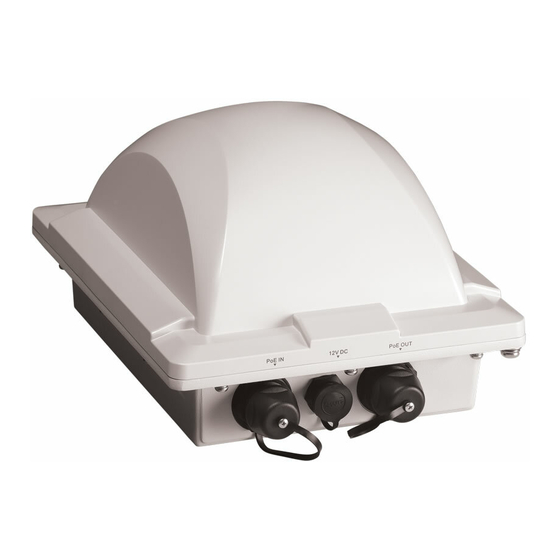
- Page 12 Before You Begin Get to Know the Access Point Features Table 1. LEDs and connectors on the AP Label Description DC Connector In addition to PoE, you can also use direct current or DC (from a battery, for example) to supply power to the Access Point.
-
Page 13: Perform A Site Survey
Before You Begin Perform a Site Survey Perform a Site Survey Before installing the Access Point, perform a site survey to determine the optimal Access Point placement or maximum range, coverage, and network performance. When performing a site survey, consider the following factors: Data rates: Range is generally inversely proportional to data rates. -
Page 14: Determine The Optimal Mounting Location And Orientation
The location and orientation that you choose for the Access Point play a critical role in the performance of your wireless network. In general, Ruckus Wireless recommends installing the Access Point away from obstructions and sources of interference and ensuring that the Access Point’s dome is pointing in the general direction of its wireless clients. - Page 15 Before You Begin Determine the Optimal Mounting Location and Orientation Figure 8. Recommended orientation for maximum vertical plane coverage Excellent Reach Limited Reach Good Reach Excellent Reach...
- Page 16 Before You Begin Determine the Optimal Mounting Location and Orientation Figure 9. Recommended orientation for maximum mesh coverage Limited Reach Excellent Excellent Reach Reach Good Reach...
-
Page 17: Become Familiar With The Installation Components
(for example, the Access Point). Figure 10. Typical installation components using both PoE and DC power sources DC power source INDOOR OUTDOOR Ground screw ZoneFlex 7762 Outdoor AP 18 AWG min green-and- yellow wire used 18 AWG min green-and-... -
Page 18: Decide How You Will Supply Power To The Access Point
For additional lightning protection, use lightning rods and lightning arrestors. WARNING: The Ruckus Wireless PoE injector (if supplied with your Access Point) is for indoor use only. Never mount the PoE injector outdoor with the Access Point. Decide How You Will Supply Power to the Access... -
Page 19: What You Will Need
Configuring the Access Point Configuring for Management by ZoneDirector Before starting this procedure, check the back panel of the Access Point (above the recess where the bottom connectors are located), and then write down the MAC address of the Access Point. You will need the MAC address to identify the Access Point on the ZoneDi- rector Web interface. - Page 20 Configuring the Access Point Configuring for Management by ZoneDirector 4. Connect one end of the other Ethernet cable to the NETWORK port on the PoE injector, and then connect the other end to ZoneDirector directly or through a hub. 5. Connect the power jack to the DC 48V IN connector on the PoE injector, and then plug the power adapter to a power source.
- Page 21 Configuring the Access Point Configuring for Management by ZoneDirector Figure 12. DC cable connector assembly DC cable Cable clamp Coupling ring Boot housing 3. Strip the DC cable for about 3/8” and each of the four conductors for about 7/32”. Figure 13.
- Page 22 Configuring the Access Point Configuring for Management by ZoneDirector Figure 14. Pinout connections for the DC cable Pinout +DC power -DC power Factory reset Ground Figure 15. Insert the conductors into the pins, crimp or solder the edges, and then insert the pins into the connector Crimp or solder the conductors before inserting them into the...
-
Page 23: Step 2: Connect The Access Point To The Same Subnet As Zonedirector
Configuring the Access Point Configuring for Management by ZoneDirector Step 2: Connect the Access Point to the Same Subnet as ZoneDirector 1. Verify that the Access Point is powered on. 2. Connect one end of an Ethernet cable to the PoE IN port on the AP. 3. -
Page 24: Configuring For Standalone Operation Or For Management By Flexmaster
Configuring the Access Point Configuring for Standalone Operation or for Management by FlexMaster Configuring for Standalone Operation or for Management by FlexMaster What You Will Need Before starting with the configuration task, make sure that you have the following require- ments ready: An administrative computer (notebook computer) running on Microsoft Windows ■... - Page 25 Configuring the Access Point Configuring for Standalone Operation or for Management by FlexMaster NOTE: Make sure that you configure the Local Area Connection properties, not the Wireless Network Connection properties. 3. When the Local Area Connection Properties dialog box appears, select Internet Protocol (TCP/IP) from the scrolling list, and then click Properties.
-
Page 26: Step 2: Connect The Access Point To The Administrative Computer
Configuring the Access Point Configuring for Standalone Operation or for Management by FlexMaster Figure 16. Sample configuration in the Internet Protocol (TCP/IP) Properties dialog box Step 2: Connect the Access Point to the Administrative Computer The procedure for connecting the Access Point to the administrative computer depends on the power source that you will be using. - Page 27 Configuring the Access Point Configuring for Standalone Operation or for Management by FlexMaster 5. Connect the power jack to the DC 48V IN connector on the PoE injector, and then plug the power adapter to a power source. The single LED on the PoE injector turns green.
- Page 28 Configuring the Access Point Configuring for Standalone Operation or for Management by FlexMaster NOTE: A waterproof connector for the RJ-45 port is supplied with the AP. You do not need to assemble the connector at this point. 2. Take the small plastic bag containing the DC connector pins and DC cord connector from the AP package.
- Page 29 Configuring the Access Point Configuring for Standalone Operation or for Management by FlexMaster Figure 20. Pinout connections for the DC cable Pinout +DC power -DC power Factory reset Ground Figure 21. Insert the conductors into the pins, crimp or solder the edges, and then insert the pins into the connector Crimp or solder the conductors before inserting them into the...
-
Page 30: Step 3: Log Into The Access Point's Web Interface
Configuring the Access Point Configuring for Standalone Operation or for Management by FlexMaster Step 3: Log Into the Access Point’s Web Interface 1. On the administrative computer, open a Web browser window. 2. In the address or location bar, type the following address: https://192.168.0.1 3. -
Page 31: Step 4: Configure The Wireless Settings
Wireless # tab. These are the essential wireless settings that will enable wireless devices on the network to associate with the Access Point. NOTE: ZoneFlex 7762 has one 2.4GHz radio and one 5GHz radio. The wireless settings for each radio need to be configured separately on the Web interface (except for the... - Page 32 Access Point uses only the radio channels allowed in your country or region. NOTE: The two radios on ZoneFlex 7762 AP are always configured with the same country code setting. If you change the country code for Radio 2.4G, for example, the same change will be automatically applied to Radio 5G.
- Page 33 4. Clear the SSID box, and then type a unique and descriptive name that you want to call this wireless network. For example, you can type Ruckus Wireless AP. This SSID is the name that will help users identify this wireless network in their wireless network connection applica- tion.
- Page 34 Configuring the Access Point Configuring for Standalone Operation or for Management by FlexMaster (Optional) Set the FlexMaster Server Address If you have a FlexMaster server installed on the network and you intend to use FlexMaster to manage the Access Point, you can set the FlexMaster server address at this point. Before starting this procedure, make sure you obtain the correct FlexMaster server URL.
- Page 35 (Optional) Enable PoE for the PoE OUT Port If you are using the supplied Ruckus Wireless PoE injector for 7762 AP (and power adapter) to supply power to the AP, you can use PoE OUT port to supply PoE to any PoE-capable device (for example, another ZoneFlex 7762 AP or an IP-based surveillance camera).
- Page 36 Figure 26. Select the Use custom PoE injector check box In addition to the supplied Ruckus Wireless PoE injector for ZoneFlex 7762 AP, you can also use DC power or a standard 802.3af/802.3at PoE injector to supply power to the AP.
-
Page 37: Step 5: Disconnect The Access Point From The Administrative Computer
You are now ready to connect the Access Point to your network. Verifying Access Point Operation Before mounting the unit, Ruckus Wireless strongly recommends that you verify that the Access Point is operating correctly. To do this, you will need to connect the Access Point... -
Page 38: Connect The Access Point To The Network
“Configure Wireless # Settings” page 29. For example, if you set the SSID to Ruckus Wireless AP, click the wireless network named Ruckus Wireless AP. 3. Click Connect. Your wireless client connects to the wireless network. After the wireless client connects to... -
Page 39: Disconnect The Access Point From The Network
Deploying the Access Point Disconnect the Access Point from the Network 1. Log in to the Access Point’s Web interface. 2. Go to the Administration > Management page. 3. Scroll down to the TR069 Status section. 4. Check the value for Last successful contact. If it shows a date in green, this indicates that the Access Point was able to communicate successfully with FlexMaster. -
Page 40: Step 2: Complete The Power Connections
Deploying the Access Point Step 2: Complete the Power Connections Figure 27. RJ-45 waterproof connector assembly RJ-45 connector (PoE IN/PoE OUT port on the AP) Clamping ring assembly Rubber-O ring Sealing nut 3. Connect the RJ-45 cable to the PoE IN port on the AP. 4. - Page 41 Deploying the Access Point Step 2: Complete the Power Connections For instructions on completing the power connection that you need to make, refer to the procedures below: Use Power Over Ethernet ■ Use DC Power ■ Use Power Over Ethernet 1.
- Page 42 Deploying the Access Point Step 2: Complete the Power Connections Use DC Power NOTE: If you already assembled the DC cord connector in “Step 1: Connect the Cables to the Access Point” page 15, you only need to connect the DC cord connector to the 12V DC port on the AP (see Step 10 and onwards).
- Page 43 Deploying the Access Point Step 2: Complete the Power Connections Figure 30. Strip the DC cable and the four conductors 3/8 inches (max) 7/32 inches (max) 5. Insert the stripped part of the conductors into the four connector pins, and then crimp the edges of the connector pins to secure the conductors.
- Page 44 Deploying the Access Point Step 2: Complete the Power Connections Figure 32. Insert the conductors into the pins, crimp or solder the edges, and then insert the pins into the connector Crimp or solder the conductors before inserting them into the connector 7.
-
Page 45: Step 3: Connect The Access Point To The Network
PoE and DC power as power sources. Figure 33. Typical installation components using both PoE and DC power sources DC power source INDOOR OUTDOOR Ground screw ZoneFlex 7762 Outdoor AP 18 AWG min green-and- yellow wire used 18 AWG min green-and-... -
Page 46: Attaching The Mounting Brackets
Attaching the Mounting Brackets What You Will Need • If you are using PoE, plug the power adapter to an AC power source. • If you are using DC power, connect the DC cable to a DC power source. 7. Check the Power LED on the Access Point. It should turn red as the AP powers on and green when it completes its power-on sequence. -
Page 47: Attaching The Bracket To A Flat Surface
Step 1: Attach the Static Bracket to the Mounting Surface Attaching the Bracket to a Flat Surface WARNING: Ruckus Wireless strongly recommends that you wear eye protection before drilling holes on the mounting surface. NOTE: The wall anchors that are supplied with the Access Point are for mounting on solid masonry walls only. - Page 48 Attaching the Mounting Brackets Step 1: Attach the Static Bracket to the Mounting Surface 3. Remove the static bracket from the mounting surface. 4. Drill an 8mm-diameter hole with a depth of 36mm-38mm into each of the four markings that you made on the mounting surface. 5.
-
Page 49: Attaching The Bracket To A Pole
Attaching the Mounting Brackets Step 1: Attach the Static Bracket to the Mounting Surface Attaching the Bracket to a Pole The Access Point can be mounted vertically or horizontally on a 30mm to 60mm (1.18 in. to 2.36 in.) pole. 1. - Page 50 Attaching the Mounting Brackets Step 1: Attach the Static Bracket to the Mounting Surface 3. Use the clamps to attach the bracket to the pole. Figure 37. Use the clamps to attach the bracket to the pole...
- Page 51 Attaching the Mounting Brackets Step 1: Attach the Static Bracket to the Mounting Surface 4. Using a 10mm flathead screwdriver, tighten the clamp locks to secure the bracket to the pole. Screw torque value must be 1.1-1.2 Newton meter (Nm). Figure 38.
-
Page 52: Step 2: Attach The Dynamic Bracket To The Access Point
Mounting the Access Point Step 2: Attach the Dynamic Bracket to the Access Point Step 2: Attach the Dynamic Bracket to the Access Point 1. Place the dynamic bracket onto the flat side of the Access Point so that the four screw holes on the bracket align with the four screw holes on the Access Point. - Page 53 Mounting the Access Point Step 2: Attach the Dynamic Bracket to the Access Point NOTE: Figures in this section show mounting on a vertical pole. Procedures for mounting on a flat surface or horizontal surface are similar. To join the two mounting brackets together: 1.
- Page 54 Mounting the Access Point Step 2: Attach the Dynamic Bracket to the Access Point 2. Align the mounting holes on the dynamic bracket with the mounting holes on the static bracket. 3. Place a split lock washer, and then a flat washer onto a hex bolt. Then insert the hex bolt into one of the mounting holes.
-
Page 55: Optional) Mounting And Connecting The 5Ghz External Antennas
(Optional) Mounting and Connecting the 5GHz External Antennas Step 2: Attach the Dynamic Bracket to the Access Point NOTE: If you have not yet determined the optimal orientation for your Access Point, refer “Determine the Optimal Mounting Location and Orientation” page 10 for orienta- tion guidelines. -
Page 56: Resetting The Access Point To Factory Default Settings
Resetting the Access Point to Factory Default Settings Step 2: Attach the Dynamic Bracket to the Access Point If you are not connecting 5GHz external antennas to the standard N-type CAUTION: antenna interfaces on the Access Point, make sure that the metal caps remain installed and securely fastened to protect the interface from elements, such as water and dirt. - Page 57 Resetting the Access Point to Factory Default Settings Step 2: Attach the Dynamic Bracket to the Access Point Figure 41. Note the location of pins 3 and 4 Pin 4 Pin 3...
- Page 58 Resetting the Access Point to Factory Default Settings Step 2: Attach the Dynamic Bracket to the Access Point 4. Install the shunt on pins 3 and 4, as shown in Figure 42 Figure 42. Install the shunt Pin 4 Pin 3...
- Page 59 Resetting the Access Point to Factory Default Settings Step 2: Attach the Dynamic Bracket to the Access Point 5. Wait 10 seconds, and then remove the shunt. Figure 43. Wait 10 seconds Figure 44. Remove the shunt...
-
Page 60: What To Do Next
What to Do Next The following are some of the post-installation tasks that Ruckus Wireless recommends. Refer to the ZoneFlex 7762 Dual Band 802.11n Outdoor Access Point User Guide for more information on configuring and managing the Access Point. Change the Administrative Password Management access to the Web interface of the Access Point is controlled through administrative user name and password.
Need help?
Do you have a question about the ZoneFlex 7762 and is the answer not in the manual?
Questions and answers