Table of Contents
Advertisement
Quick Links
Download this manual
See also:
Installation Manual
Advertisement
Table of Contents

Subscribe to Our Youtube Channel
Related Manuals for Yeastar Technology MyPBX U520


Summary of Contents for Yeastar Technology MyPBX U520
- Page 1 MyPBX U520 Installation Guide MyPBX U520 Installation Guide Version: V1.0 Yeastar Technology Co., Ltd Date: 25 , July, 2012 http://www.yeastar.com 1/14...
-
Page 2: Table Of Contents
3.2.3 Connection of FXS ports ....................10 3.2.4 Power Connection ......................10 3.2.5 Overall Flow Chart ......................11 4. MYPBX U520 BASIC CONFIGURATIONS ..................11 4.1 Factory Defaults ....................... 11 4.2 Logging in the Web Configuration Panel ................. 12 4.3 Network Settings ......................13 4.4 Extensions Setup and management ................. -
Page 3: Preparation Before Installation
This Guide explains how to install MyPBX U520, how to configure MyPBX U520 via web interface, how to add extensions, and make/receive calls via PSTN lines. -
Page 4: Hardware Specifications
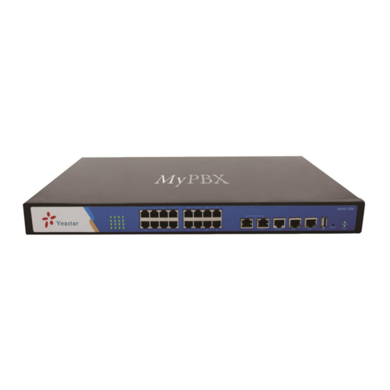
MyPBX U520 Installation Guide Screws 8 screws (φ3.0*6mm) for mounting ears; 4 screws (φ3.0*8mm) for hard disk brackets Sheet 1 MyPBX U520 Packing List 2. Hardware Specifications 2.1 Overview Figure 2-1 MyPBX U520 2.2 LED Indicators and Ports Figure 2-2 MyPBX U520 Front Panel http://www.yeastar.com... - Page 5 MyPBX U520 Installation Guide Figure 2-3 MyPBX U520 Rear Panel Indication Status Description Power Power status The power is switched on The power is switched off MyPBX status Blinking MyPBX is running properly Not Blinking/Off MyPBX goes wrong 1-16 FXO port status Red light The red light is blinking: the PSTN line hasn’t been...
-
Page 6: Specifications And Operating Environment
MyPBX U520. 3.1 Placement Instructions Ambient Temperature: to avoid overheating, please do not run MyPBX U520 in the place where the ambient temperature is above 122℉ (50℃). Ventilation: please make sure that the device has good ventilation around. -
Page 7: Installation Instructions
ADSL modem. LAN Port Connection Connect one end of a network cable to the LAN port of MyPBX U520, and the other end to any port of company’s LAN switch/router. If the LAN port is connected to PC directly (not via a switch), please use cross-over cable. - Page 8 MyPBX U520 Installation Guide When connected to the E1 line, RX- of E1 port should be connected to TX- of E1 line; RX+ of E1 port should be connected to TX+ of E1 line; TX- of E1 port should be connected to RX- of E1 line; TX+ of E1 port should be connected to RX+ of E1 line.
- Page 9 3. Connection of GSM/UMTS ports If No.3 and No.7 connectors are GSM/UMTS Ports, the steps of connection are as below: Step 1: Open the Upper case of MyPBX U520 Step 2: Insert the SIM card: Figure 3-4 Inserting the SIM Card Step 3: Connect the antenna Once completed, the No.3 and No.7 LED lights would turn red as below figure:...
-
Page 10: Connection Of Fxs Ports
MyPBX U520 Installation Guide 4. Connection of BRI ports The BRI port could be connected to the BRI line and the BRI port of a traditional PBX with a BRI RJ45-RJ11 cable. For instance, if No.14 and No.16 connectors are BRI ports, the connection could be depicted as below: Figure 3-6 Connection of BRI ports 3.2.3 Connection of FXS ports... -
Page 11: Overall Flow Chart
MyPBX U520 Installation Guide switch on the power. Then MyPBX U520 will start booting. In the meantime, users would see that the ‘POWER’ and ‘RUN’ indicator lights would turn on. Please switch off the power before plugging or unplugging the cables. -
Page 12: Logging In The Web Configuration Panel
MyPBX U520 Installation Guide 4.2 Logging in the Web Configuration Panel Firstly, please check if the IP address that assigns to the network port (LAN or WAN) is in the same segment with the PC and which can be connected when commit ‘Ping +MyPBX IP address’ command. Start the browser on PC. -
Page 13: Network Settings
MyPBX U520 Installation Guide the changes take effect. 4.3 Network Settings After logging in the admin configuration interface, generally the first step is to configure the IP address. If both the WAN and LAN ports are connected to the network, their IP addresses need to be configured. If not, just configuring the IP address of the LAN port which is connected to the local area network of the company is OK. -
Page 14: Making/Receiving Calls
Note: After resetting, all the configurations made by the admin would be erased. 5. Conclusion This Installation Guide only explains the installation and basic settings of MyPBX U520 for making and receiving calls. For more functionality and advanced settings of MyPBX U520, please refer to the relative documents as below: “MyPBX U520 Datasheet”...
Need help?
Do you have a question about the MyPBX U520 and is the answer not in the manual?
Questions and answers