
Related Manuals for Queclink GV200


Summary of Contents for Queclink GV200
-
Page 1: User Manual
GV200 GSM/GPRS/GPS Tracker User Manual TRACGV200UM001 Revision: 1.05N sales@eddywireless.com... - Page 2 Suitable Hardware Version General Notes Queclink offers this information as a service to its customers, to support application and engineering efforts that use the products designed by Queclink. The information provided is based upon requirements specifically provided to Queclink by the customers. Queclink has not undertaken any independent search for additional relevant information, including any information that may be in the customer’s possession.
-
Page 3: Table Of Contents
GV200 User Manual Contents Contents ............................2 Table Index............................3 Figure Index ............................4 0. Revision History ...........................5 1. Introduction...........................6 1.1. Reference..........................6 1.2. Terms and Abbreviations.....................6 2. Product Overview .........................7 2.1. Appearance..........................7 2.2. Parts List..........................8 3. Interface Description........................9 3.1. SIM Card Interface......................9 3.2. Antenna Interface ......................10 3.2.1. -
Page 4: Table Index
GV200 User Manual Table Index TABLE 1: REFERENCE..........................6 TABLE 2: TERMS AND ABBREVIATIONS ..................6 TABLE 3: PART LIST ..........................8 TABLE 4: GPS ANTENNA SPECIFICATION ..................10 TABLE 5: GSM ANTENNA SPECIFICATION ..................11 TABLE 6: THE DEFINITION OF 24 PIN CONNECTOR..............12 TABLE 7: THE DESCRIPTION OF 24 PIN ..................13... -
Page 5: Figure Index
FIGURE 1: APPEARANCE OF GV200....................7 FIGURE 2: SIM CARD INTERFACE ....................9 FIGURE 3: SIM CARD INSTALLATION ..................9 FIGURE 4: THE ANTENNAS OF GV200 ..................10 FIGURE 5: THE SEQUENCE OF 24 PIN CONNECTOR ..............12 FIGURE 6: EXAMPLE OF POWER CONNECTION..............14 FIGURE 7: THE KEY OF RESET .....................14 FIGURE 8: IGNITION DETECTION ....................15... -
Page 6: Revision History
3.5 2> Modify the max current of RELAY in chapter 3.3.12 3> Add GSM light mode to indicate that SIM card inserted into GV200 need pin code to unlock. 1.03 2011-10-21 Leo LEI 1> Change the color of TXD and TXD2 from Orange to Orange/Gray in Table 7 2>... -
Page 7: Introduction
Battery or scheduled GPS position along with many other useful functions. Users can also use GV200 to monitor the status of a vehicle and control the vehicle with its external relay output. System Integrators can easily setup their tracking systems based on the full-featured @Track protocol. -
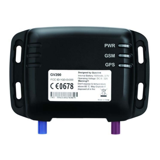
Page 8: Product Overview
GV200 User Manual 2. Product Overview 2.1. Appearance Figure 1: Appearance of GV200 TRACGV200UM001 - 7 -... -
Page 9: Parts List
GV200 User Manual 2.2. Parts List Table 3: Part List Name Picture GV200 Locater User Cable GPS Antenna GSM Antenna 12V DC power supply (Optional) USB-232 data cable (Optional) Uart Cable (Optional) Extend Cable (Optional) TRACGV200UM001 - 8 -... -
Page 10: Interface Description
GV200 User Manual 3. Interface Description 3.1. SIM Card Interface To install the SIM card Step 1: Press the yellow button on the right side of SIM card slot to eject the SIM card holder. Figure 2: SIM Card Interface Step 2: Put the SIM card on the SIM card holder. -
Page 11: Antenna Interface
3.2. Antenna Interface 3.2.1. Install Antennas There are two Fakra antenna connectors on GV200, the blue one for GPS and the purple one for GSM. Please find the GPS antenna and GSM antenna in package box. Install them to the correct Fakra connector as following. -
Page 12: Gsm Antenna Specification
GV200 User Manual 3.2.3. GSM antenna specification Table 5: GSM antenna specification GSM antenna specification Frequency and bandwidth GSM850: 824MHz to 894MHz EGSM900: 880MHz to 960MHz DCS1800: 1710MHz to 1885MHz PCS1900: 1850MHz to 1990MHz Direction: Omnidirection Gain: Passive: >0dBi Impedance: 50Ω... -
Page 13: User Interface
GV200 User Manual 3.3. User Interface 3.3.1. Interface Definition There is a 24 PIN connector on GV200. It contains the interface of power, I/O, RS232, microphone, speaker, etc. The sequence and definition of the 24 PIN connector are showed in following figure:... -
Page 14: Power Connection
GV200 User Manual Table 7: The description of 24 PIN Index Color of User Description Comment cable Black Analog Ground For microphone and analog inputs Blue Microphone Input MIC+ Analog Input 1 Green (Input range: 0 ~ For resistance-type sensors 2.7V) -
Page 15: Output
PIN 19 is named as VOUT which can drive a controlled 5V output for user. Please note that if user wants to drive a 5V output, GV200 must be supplied by external power. In default, 5V output is disabled, user can use AT commend to enabled 5V output. The max drive current of VOUT is 0.25A. -
Page 16: Ignition Control
GV200 User Manual Table 8: Electrical conditions of ignition detect Logical State Electrical State Active 5.0V to 32V Inactive 0V to 3V or Open It is strongly recommended to connect this pin to ignition key to support the power saving function when the vehicle is off. -
Page 17: Electrical Conditions For Digital Inputs
GV200 User Manual Table 9: Electrical conditions of ignition control Logical State Electrical State Enable <1.5V, drive current is 0.2A Disable Open or the pull-up voltage (max 32V) User can use this pin to control a relay output. An example to control the ignition key is showed in following figure. -
Page 18: Digital Input Without Interrupt
GV200 User Manual Figure 10: Example connection for negative Trigger digital inputs For positive trigger inputs the electrical conditions are: Table 11: Electrical conditions of positive trigger digital inputs Logical State Electrical State Active 5.0V to 32V Inactive 0V to 3V or Open... -
Page 19: Digital Input With Interrupt
Figure 12: Example connection of panic button 3.3.10. Analog Input The PIN 3/5/7 are used for analog to digital converter. GV200 can support different type sensors such as resistance-type and capacitance-type due to the differences between the three analog inputs. Please note it is an average value based on the sample rate from 2 to 24 seconds, which means the burst on voltage input may not be detected. -
Page 20: Figure 13: Ain1 Connect To Ntc Resistor
AIN2 (PIN 5) and AIN3 (PIN 7) are designed to support capacitance-type sensors. In default GV200 only support capacitance-type sensors which voltage range is 0 ~ 2.7V. If user wants to use the capacitance-type sensors which voltage range is out of 0 ~ 2.7V, a level transfer board must be used between capacitance-type sensors and GV200. -
Page 21: Digital Output
GV200 User Manual 3.3.11. Digital Output The outputs are Open-Drain type with no internal pull-up resistor which also be used to control a relay. It means that the user has to connect a pull-up resistor or a relay coil between the output pin and any positive voltage (32V max.) to generate a correct output. -
Page 22: Figure 16: The Example Connection To Drive A Relay
GV200 User Manual Figure 16: The example connection to drive a relay Note: All outputs are internally pulled up to PWR pin by a diode. So no external flyback diode is needed when the output is connected to an inductive load. -
Page 23: Indicator Light Description
GV200 User Manual 3.4. Indicator Light Description Figure 17: LEDs on GV200 There are three LEDs in GV200, the description as follow. TRACGV200UM001 - 22 -... -
Page 24: Table 13: Description Of Leds
Backup battery is disabled and external power supply is connected. GSM LED GV200 is in searching GSM network state. Fast flashing GV200 has been registered to GSM network. Slow flashing SIM card inserted to GV200 need pin code to unlock. TRACGV200UM001 - 23 -... -
Page 25: Audio Interface
There is a differential output for speaker and a signal-ended microphone on GV200. Please note that the PIN 1 is analog ground and should not be used as a power ground. GV200 has an audio amplifier internally, so it can drive a louder speaker directly. It is recommended to connect an 8 Ohm speaker to speaker interface, and an electret microphone is also recommended. -
Page 26: Uart Interface
UART2 is used to communicate with external devices like CAN Bus module and RFID reader. PIN 13 is a control signal which is named as data terminal ready (DTR). When the GV200 is sleeping, a high level on DTR will wake up UARTs of GV200. -
Page 27: Gv200_Relay_Cable
GV200_RELAY_CABLE is an assembled harness cable which contains a cut relay output and some digital input and outputs. It can easily help the user to install the GV200 in vehicle with engine cutting function. The diagram of the GV200_RELAY_CABLE is showed in...
Need help?
Do you have a question about the GV200 and is the answer not in the manual?
Questions and answers