
Related Manuals for Queclink GV50VC


Summary of Contents for Queclink GV50VC
- Page 1 GV50VC User Manual GV50VC User Manual CDMA2000-1X/GPS Tracker TRACGV50VCUM001 Version: 1.01 GV50VC TRACGV50VCUM0010...
- Page 2 TRACGV50VCUM001 General Notes Queclink offers this information as a service to its customers, to support application and engineering efforts that use the products designed by Queclink. The information provided is based upon requirements specifically provided to Queclink by the customers. Queclink has not undertaken any independent search for additional relevant information, including any information that may be in the customer’s possession.
-
Page 3: Table Of Contents
2.6. Digital Output/ Input connection ..................10 2.7. Digital Output ........................12 3. GettingStarted ..........................14 3.1. Part List ..........................14 3.2. GV50VC External Cable Interface ..................14 3.3. Turn on/Turn off ....................... 15 4. Troubleshooting and Safety Info ....................16 4.1. Troubleshooting ....................... 16 4.2. - Page 4 TABLE 6: ELECTRICAL CHARACTERISTICS AS DIGITAL OUTPUTS ............. 10 TABLE 7: ELECTRICAL CHARACTERISTICS AS DIGITAL INPUTS ..............11 TABLE 8: ELECTRICAL CHARACTERISTICS AS DIGITAL OUTPUTS ............. 12 TABLE 9: PART LIST ..........................14 TABLE 10: GV50VC USER CABLE COLOUR DEFINITION ................14 TRACGV50VCUM0013...
- Page 5 GV50VC User Manual Figure Index FIGURE 1: GV50VC APPEARANCE ......................7 FIGURE 2: THE 7 PIN CONNECTOR ON THE GV50VC ................7 FIGURE 3: TYPICAL POWER CONNECTION ....................9 FIGURE 4: TYPICAL IGNITION DETECTION....................10 FIGURE 5: AS DIGITAL OUTPUT INTERNAL DRIVE CIRCUIT ..............10 FIGURE 6: TYPICAL CONNECTION WITH BUZZER AS DIGITAL OUTPUT...........
-
Page 6: Revision History
GV50VC User Manual 0. Revision history Revision Date Author Description of change 1.00 2016-03-18 Docter Xu Initial Version TRACGV50VCUM0015... -
Page 7: Introduction
GPS position as well as many other useful functions. Users can also use GV50VC to monitor the status of a vehicle and control the vehicle by its external relay output. System Integrators can easily setup their tracking systems based on the full-featured @Track protocol. -
Page 8: Product Overview
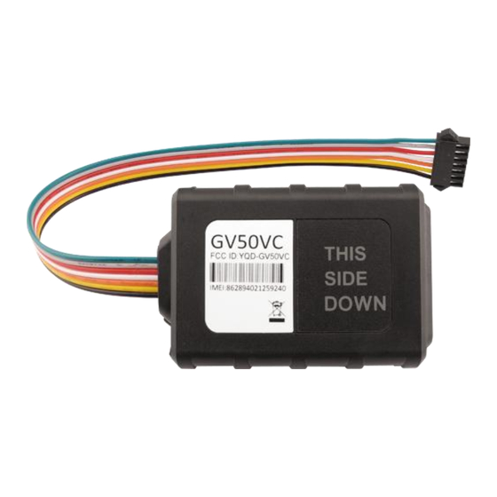
Figure 1: GV50VC Appearance 2.2. Interface Definition The GV50VC has a 7 PIN interface connector. It contains the connections for power, I/O. The sequence and definition of the7PIN connector are shown in following figure: Figure 2: The 7 PIN connector on the GV50VC... -
Page 9: Led Description
Ignition input, positive trigger OUT1/IN1 Digital Output/ Input OUT2 Open drain,150mA max 2.3. LED Description GV50VC has two status LED which contain CELL LED and GPS LED. CELL Device is searching CELL network Fastflashing (note1) Devicehas registered to CELL network. -
Page 10: Ignition Detection
GV50VC User Manual Figure 3: Typical Power Connection 2.5. Ignition Detection IGN (Pin4) is used for ignition detection. It is strongly recommended to connect this pin to ignition key “RUN” position as shown up. An alternative to connecting to the ignition switch is to find a non-permanent power source that is only available when the vehicle is running. -
Page 11: Digital Output/ Input Connection
Figure 4: Typical Ignition Detection 2.6. Digital Output/ Input connection OUT1/IN1(PIN5) is a digital Output/Input connection on GV50VC.Ti is of open drain type and the maximum drain current is150mA as a digital Output and a negative trigger as digital Input Electrical Characteristics of the digital input. -
Page 12: Table 7: Electrical Characteristics As Digital Inputs
GV50VC User Manual Figure 6: Typical Connection with buzzer AS Digital Output Table 7: Electrical Characteristics AS Digital Inputs Logical State Electrical Characteristics Active 0V to 0.8V Inactive Open The following diagram shows the recommended connection of a digital input. -
Page 13: Digital Output
GV50VC User Manual 2.7. Digital Output There is a digital output (PIN6) on GV50VC. Ti is of open drain type and the maximum drain current is 150mA. Figure 8: Digital Output Internal Drive Circuit Table 8: Electrical Characteristics AS Digital Outputs... -
Page 14: Figure 9: Typical Connection With Relay
GV50VC User Manual Figure 9: Typical Connection with Relay TRACGV50VCUM00113... -
Page 15: Gettingstarted
GV50VC User Manual 3. GettingStarted 3.1. Part List Table 9: Part List Name Picture GV50VC Locator 73mm*50mm*13.2mm 3.2. GV50VC External Cable Interface Table 10: GV50VC User Cable Colour definition Definition Colour PIN No Cable Green Gray White OUT1/IN1 Orange OUT2... -
Page 16: Turn On/Turn Off
GV50VC User Manual 3.3. Turn on/Turn off Turn On: Connect device to external battery, and it will turn on automatically, PWR LED will light on. Turn Off: Disconnect device from external battery, and it will turn off. TRACGV50VCUM00115... -
Page 17: Troubleshooting And Safety Info
Too high temperature will damage the device or even cause battery explosion. Please do not use GV50VC on the airplane or near medical equipment. RF Exposure Statement: For the product,under normal use condition is at least 20cm away from the b ody of the user ,the user must keeping at least 20cm distance to the product.
Need help?
Do you have a question about the GV50VC and is the answer not in the manual?
Questions and answers