
Related Manuals for Queclink GV75MG


Summary of Contents for Queclink GV75MG
- Page 1 GV75MG User Manual GV75MG User Manual EGPRS/LTE Cat-M1/LTE Cat-NB1/GNSS Tracker QSZTRACGV75MGUM0101 Version: 1.01 QSZTRACGV75MGUM0101...
- Page 2 QSZTRACGV75MGUM0101 General Notes Queclink offers this information as a service to its customers, to support application and engineering efforts that use the products designed by Queclink. The information provided is based upon requirements specifically provided to Queclink by the customers. Queclink has not undertaken any independent search for additional relevant information, including any information that may be in the customer’s possession.
-
Page 3: Table Of Contents
GV75MG User Manual Contents 0. Revision History ..........................1 1. Introduction ..........................2 1.1. GV75MG Series Products ....................2 1.2. Reference ........................... 2 1.3. Terms and Abbreviations ....................2 2. Product Overview .......................... 3 2.1. Product Appearance ......................3 2.2. LED Description ........................3 2.3. -
Page 4: Revision History
GV75MG User Manual 0. Revision History Version Date Author Description of change 1.00 2019-09-05 Heymi Lin Initial Version 1.01 2019-11-11 Heymi Lin Modified Table 4 and Table 5 QSZTRACGV75MGUM0101... -
Page 5: Introduction
GV75MG User Manual 1. Introduction The GV75MG is a micro-type GSM and LTE GPS tracker designed for a wide variety of vehicle tracking applications. It has I/O interfaces that can be used for monitoring or controlling external devices. The built-in GPS receiver has superior sensitivity and fast initial positioning. Their multiband LTE Cat-M1 and Cat-NB1 allow the GV75MG location to be monitored in real time or periodically tracked by a backend server or mobile devices. -
Page 6: Product Overview
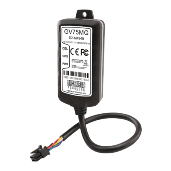
Figure 1. GV75MG Appearance 2.2. LED Description Figure 2. GV75MG LEDs There are three LEDs on GV75M. For details, please see the table below. Table 4. GV75MG Series LED Description Fast flashing The device is searching GSM network. CELL Slow flashing The device has been registered on GSM network. -
Page 7: Parts List
External power is inserted and backup battery is fully charged. Note: 1. Fast flashing intervals are about 100ms ON/200ms OFF. 2. Slow flashing intervals are about 200ms ON/1000ms OFF. 2.3. Parts List Table 5. GV75MG Series Parts List Name Picture Description EGPRS/LTE Cat-M1/LTE... -
Page 8: Interface Definition
GV75MG User Manual 3. Interface Definition The GV75MG has an 8-pin interface connector. It contains the connections for power and I/O. The sequence and description of the connector are shown in the following figure: Figure 3. 8-pin Connector of the GV75MG Table 6. -
Page 9: Device Cable Color
GV75MG User Manual 4. Device Cable Color Table 7. GV75MG Device Cable Color Definition Definition Color Pin No. Cable Gray Violet OUT1 Blue OUT2 Green White Yellow Black QSZTRACGV75MGUM0101... -
Page 10: Getting Started
GV75MG User Manual 5. Getting Started 5.1. Opening and Closing the Casing Figure 4. Open Top Cover To open/close: Loosen or fasten the screws to open or to close. 5.2. Installing a SIM Card Install the SIM card into the holder when power is off as shown blow. Take care to align the cut mark, and then close the case. -
Page 11: Power Supply Connection
Inactive 0V to 3V or Open loop Figure 7. Typical Ignition Detection 5.5. Digital Input There is a negative trigger input on GV75MG. For negative trigger input, the electrical conditions are: Table 9. Electrical Characteristics of Digital Input Logical State... -
Page 12: Digital Outputs
Open or the pull-up voltage (max 32V) Note: 1. The relay output can be latched by software, so even if GV75MG is restarted or powered down in some cases, the relay output will not change. To use the latch function, the main power and backup battery should work normally. -
Page 13: Uart Interface
5.7. UART Interface There is one UART interface on GV75MG. UART is used for configuration and firmware upgrade. Please note that the UART interfaces are all of RS232 level. For RS232, valid signal levels are 3V to 15V and -3V to -15V, and the -3V to +3V is not a valid level. -
Page 14: Installation Precautions
GV75MG User Manual 6. Installation Precautions Firmly install the device to a reliable surface to prevent falling off. Make the side with antenna face sky to have better signal reception. Do not install the device under metal surface or in enclosed environments having difficulty in getting GPS and network signal. -
Page 15: Troubleshooting And Safety Info
GV75MG User Manual 7. Troubleshooting and Safety Info 7.1. Troubleshooting Table 11. GV75MG Troubleshooting List Problem Possible Reason Solution After the device is turned The signal is too weak. The Move the device to a place with on, the CEL LED always device isn’t registered to the... -
Page 16: Appendix: Supported Accessories
GV75MG User Manual 8. Appendix: Supported Accessories Currently, no external accessory is supported. QSZTRACGV75MGUM0101...
Need help?
Do you have a question about the GV75MG and is the answer not in the manual?
Questions and answers