
Related Manuals for Queclink GV600MA


Summary of Contents for Queclink GV600MA
- Page 1 GV600 User Manual GV600MA User Manual GPS Tracker QSZTRACGV600UM0101 Version: 1.01...
- Page 2 QSZTRACGV600UM0101 General Notes Queclink offers this information as a service to its customers, to support application and engineering efforts that use the products designed by Queclink. The information provided is based upon requirements specifically provided to Queclink by the customers. Queclink has not undertaken any independent search for additional relevant information, including any information that may be in the customer’s possession.
-
Page 3: Table Of Contents
2.1. GV600MA Products ......................4 2.2. Parts List ..........................4 2.3. Interface Definition ......................4 2.4. GV600MA Standard Cable Color ..................5 3. Getting Started ..........................6 3.1. Open and Close the Case ..................... 6 3.2. Install a SIM Card ......................... 7 3.3. - Page 4 Table 4. Parts List ..........................4 Table 5. Description of 18-pin Connections ..................4 Table 6. GV600MA Standard Cable Color Definition ................. 5 Table 7. Electrical Characteristics of Ignition Detection ..............8 Table 8. Electrical Characteristics of the Digital Inputs ..............9 Table 9.
- Page 5 GV600MA User Manual Figure Index Figure 1. The 18-pin Connector on the GV600MA ................4 Figure 2. Open the Case ........................6 Figure 3. SIM Card Installation ......................7 Figure 4. Backup Battery Installation ....................7 Figure 5. External Power Supply Connection ..................8 Figure 6.
-
Page 6: Revision History
GV600MA User Manual 0. Revision History Version Date Author Description of Change 1.01 Dec,2018 Arry Wang Initial QSZTRACGV600UM104... -
Page 7: Introduction
Their built-in GPS receiver has superior sensitivity and fast initial positioning. Different models allow the GV600MA’ location to be monitored in real time or periodically tracked by a backend server and mobile devices. System integration is straightforward as complete documentation is provided for the full featured @Track protocol. -
Page 8: Product Overview
Fuel Level Sensor RS232 DUT-E 2.3. Interface Definition The GV600MA Tracker has an 18-pin interface connector which contains the connections for power, I/O, TTL, etc. The sequence and definition of the 18-pin connector are shown in the following figure: Figure 1. The 18-pin Connector on the GV600MA Table 5. -
Page 9: Gv600Ma Standard Cable Color
Open drain output4 150mA max drive current EX_RX UART RXD RS232 EX_TX UART TXD RS232 UART RXD TTL UART TXD TTL 2.4. GV600MA Standard Cable Color Table 6. GV600MA Standard Cable Color Definition Definition Color Pin No. Connector Pin No. Color Definition... -
Page 10: Getting Started
GV600MA User Manual 3. Getting Started 3.1. Open and Close the Case Open the Case To open: Use a cross screwdriver to loosen the four screws and then lift the top case gently. To close: Align the top case with the bottom case and then tighten the four screws. -
Page 11: Install A Sim Card
SIM card is pushed into the SIM holder completely. Close the case. Figure 2. SIM Card Installation 3.3. Install the Internal Backup Battery GV600MA has an internal backup Li-ion battery (5200mAH). Figure 3. Backup Battery Installation QSZTRACGV600UM0101... -
Page 12: Power Supply Connection
GV600MA User Manual 3.4. Power Supply Connection PWR (pin 1 or pin 2)/GND (pin 3 or pin 4) are the power input pins. The input voltage range is from 8V to 32V. The device is designed to be installed in vehicles that operate on 12V or 24V systems without the need of external transformers. -
Page 13: Digital Inputs
GV600MA User Manual position of the vehicle ignition switch as shown above. An alternative to connect to the ignition switch is to find a non-permanent power source that is only available when the vehicle is running, for example, the power source for the FM radio. -
Page 14: Analogue Inputs
GV600MA User Manual 3.7. Analogue Inputs There is one analogue input on GV600MA, and the analogue input voltage range is from 0 to 32V. The following picture shows the recommended connection. Figure 7. Typical Analogue Input Connection Note: Pin 6 is a multifunction pin: it can be configured as an analogue input. - Page 15 GV600MA User Manual Figure 9. Typical Connection with a Relay Figure 10. Typical Connection with a LED Figure 11. Typical Connection with a Buzzer QSZTRACGV600UM0101...
-
Page 16: Device Status And Led
GV600MA User Manual Figure 12. Typical Connection with Other Devices Note: 1. OUT1 will latch the output state during reset. 2. Pay attention to the polarity of the relay if it is pre-installed with an internal flyback diode during connection. Install an additional diode externally if there is no pre-installed internal diode. -
Page 17: Temperature Sensor Interface
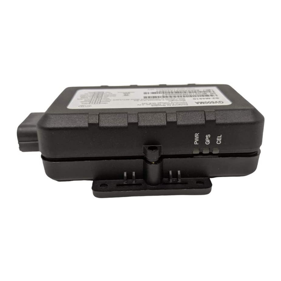
GV600MA User Manual Figure 13. GV600MA LEDs on the Case Note: 1. CELL LED cannot be configured. 2. GPS LED and PWR LED can be configured to turn off by using the configuration tool. 3. Fast flashing: for CELL LED is about 100ms ON/800ms OFF; for GPS LED and PWR LED is about 100ms ON/100ms OFF. -
Page 18: Serial Port/Uart Interface
GV600MA User Manual 3.11. Serial Port/UART Interface There are two lines dedicated to the Serial Port/UART interface (TXD and RXD). TXD and RXD are standard TTL signal. Figure 15. Typical Connection with USB to TTL Serial Port QSZTRACGV600UM0101... -
Page 19: Support Peripheral List
GV600MA User Manual 4. Support Peripheral list Name Description Temperature Sensor GV600MA Temperature Sensor Fuel level sensor Digital RS232 (DUT-E COM Protocol) 4.1. Bluetooth The device role of Bluetooth could be Master and Slave. When the device role is Slave, the device will provide below services: device information service, battery information service, virtual serial port service.
Need help?
Do you have a question about the GV600MA and is the answer not in the manual?
Questions and answers