
Related Manuals for Queclink GV65


Summary of Contents for Queclink GV65
-
Page 1: User Manual
GV55 User manual Compact Vehicle Tracking Device Model: GV65 User Manual TRACGV3SUM001 - 1 -... - Page 2 TRACGV65UM001 General Notes Queclink offers this information as a service to its customers, to support application and engineering efforts that use the products designed by Queclink. The information provided is based upon requirements specifically provided to Queclink by the customers. Queclink has not ...
-
Page 3: Table Of Contents
GV65 User Manual Contents Contents ..................................3 1 Revision History ...............................6 2 Introduction ................................7 2.1. Reference ..............................7 2.2. Terms and Abbreviations ..........................7 3 Product Overview ..............................8 3.1. Check Parts List ............................8 3.2. Parts List ..............................9 3.3. Interface Definition .............................9 3.4. GV65 User Cable Colour .......................... 10 4 Get Started ................................ 11 4.1. Open the Case ............................11 4.2. Close the Case ............................11 4.3. Install a SIM Card ............................12 4.4. Power Connection .............................12 4.5. Ignition Detection............................13 4.6. Digital Inputs .............................14 4.7. Analog Inputs ............................ 14 4.8. Digital Outputs ............................15 4.9. Device Status LED ........................... .16 4.10. 1‐wire Device Connection ........................18 5 FCC Warning .................................20 5.1. FCC Radiation Exposure Statement ......................20 TRACGV65UM001 - 3 -... - Page 4 GV65 User Manual Table Index TABLE 1. GV65 PROTOCOL REFERENCE ...................... 7 TABLE 2. TERMS AND ABBREVIATIONS ...................... 7 TABLE 3. PARTS LIST ............................ 9 TABLE 4. DESCRIPTION OF 10 PIN CONNECTIONS .................. 10 TABLE 5. GV65 USER CABLE COLOUR DEFINITION .................. 10 TABLE 6. ELECTRICAL CHARACTERISTICS OF IGNITION DETECTION ............13 TABLE 7. ELECTRICAL CHARACTERISTICS OF THE DIGITAL INPUTS .............. 14 TABLE 8. ELECTRICAL CHARACTERISTICS OF DIGITAL OUTPUTS ..............15 TABLE 9. DEFINITION OF DEVICE STATUS AND LED .................. 18 TRACGV65UM001 - 4 -...
- Page 5 GV65 User Manual Figure Index THE 10 PIN CONNECTOR ON THE GV65 .................. 9 FIGURE 1. FIGURE 2. OPEN THE CASE .......................... 11 CLOSE THE CASE ........................... 11 FIGURE 3. FIGURE 4. SIM CARD INSTALLATION ...................... 12 FIGURE 5. TYPICAL POWER CONNECTION .....................13 FIGURE 6. TYPICAL IGNITION DETECTION ..................... 13 FIGURE 7. TYPICAL DIGITAL INPUT CONNECTION .................. 14 FIGURE 8. TYPICAL DIGITAL INPUT CONNECTION .................. 15 FIGURE 9. DIGITAL OUTPUT INTERNAL DRIVE CIRCUIT ................. 15 FIGURE 10. TYPICAL CONNECTION WITH RELAY ..................... 16 TYPICAL CONNECTION WITH LED .................... 16 FIGURE 11. GV65 LED ON THE CASE ........................17 FIGURE 12. TYPICAL CONNECTION WITH 1‐WIRE DEVICE ................19 FIGURE 13. TYPICAL CONNECTION WITH IBUTTON READER ................19 FIGURE 14. TYPICAL CONNECTION WITH TEMPERATURE SENSOR ..............20 FIGURE 15. TRACGV65UM001...
-
Page 6: Revision History
GV65 User Manual 1 Revision History Revision Date Author Description of change R1.00 2015‐06‐09 Caesar Geng Initial TRACGV65UM001 - 6 -... -
Page 7: Introduction
850/900/1800/1900. Its location can be monitored in real time or periodically tracked by a backend server or other specified terminals. The GV65 has multiple input/output interfaces that can be used for monitoring or controlling external devices. Based on the integrated @Track protocol, the GV65 can communicate with a backend server through the GPRS network to transfer reports of emergency, geo‐fence boundary crossings, scheduled GPS position and many other useful reporting features. Users can also use GV65 to monitor the status of a vehicle and control the vehicle by its external relay output. System integrators can easily set up their tracking systems based on the full‐featured @Track protocol. The device have a expansion external GPS antenna 2.1. Reference Table 1. GV65 Protocol Reference SN Document name Remark ... -
Page 8: Product Overview
GV65 User Manual 3 Product Overview 3.1. Check Parts List Before starting, check whether all the following items have been included with your GV65. If anything is missing, please contact your supplier. TRACGV65UM001 - 8 -... -
Page 9: Parts List
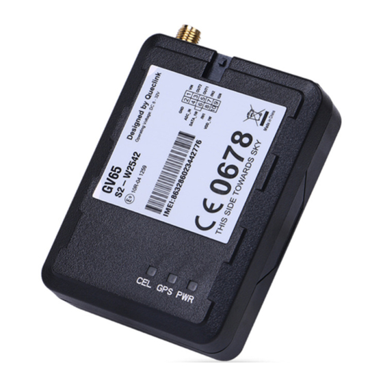
GV65 User manual 3.2. Parts List Table 3. Parts List Name Picture 73mm*54mm*22.7mm GV65 Locator User Cable DATA_CABLE_M (Optional) 3.3. Interface Definition The GV65 has a 10 PIN interface connector. It contains the connections for power, I/O, etc. The sequence and definition of the 10PIN connector are shown in the following figure: Figure . . The 10 PIN Connector on the GV65 TRACGV65UM001 - 9 -... -
Page 10: Gv65 User Cable Colour
GV65 User manual Table 4. Description of 10 PIN Connections Index Description Comment VIN External DC power input, 8‐32V 1 2 GND GND 3 OUT2 Open drain, 150 mA max 4 ADC_IN Fuel ADC input 5 OUT1 Open drain, 150 mA max ,with latch circuit 6 DATA_1W 1‐wire data bus 7 /IN2 Digital input, negative trigger 8 /IN1 Digital input, negative trigger 9 IGN Ignition input, positive trigger 10 VDD_1W 1‐wire device power output ... -
Page 11: Get Started
GV65 User Manual 4 Get Started 4.1. Open the Case Figure 2. Open the Case Insert the triangular‐pry‐opener into the gap on both sides of the case as shown above, and push the opener up until the case is unsnapped. 4.2. Close the Case Figure 3. Close the Case TRACGV65UM001 - 11 -... -
Page 12: Install A Sim Card
GV65 User manual Place the cover on the bottom in the position as shown in the figure above. Press the front case and the back case until it snaps. 4.3. Install a SIM Card Open the case and ensure the unit is not powered (unplug the 10Pin cable). Slide the holder right to open the SIM card. Insert the SIM card into the holder as shown below with the gold‐colored contact area facing down. Take care to align the cut mark. Close the SIM card holder. Close the case. Figure 4. SIM Card Installation 4.4. Power Connection VIN (PIN1)/GND (PIN2) are the power input pins. The input voltage range for this device is from 8V to 32V. The device is designed to be installed in vehicles that operate on 12V or 24V systems without the need for external transformers. -
Page 13: Ignition Detection
GV65 User manual Figure 5. Typical Power Connection 4.5. Ignition Detection Table 6. Electrical Characteristics of Ignition Detection Logical status Electrical status 8.0V to 32V Active Inactive 0V to 3V or open Figure 6. Typical Ignition Detection IGN (Pin9) is used for ignition detection. It is strongly recommended to connect this pin to ignition key “RUN” position as shown above. An alternative to connecting to the ignition switch is to find a non‐permanent power source that is only available when the vehicle is running. For example, the power source for the FM radio. IGN signal can be configured to start transmitting information to the backend server when ... -
Page 14: Digital Inputs
GV65 User manual 4.6. Digital Inputs There are two general purpose digital inputs on GV65. They are all negative triggers. Table . . Electrical Characteristics of the Digital Inputs Logical status Electrical characteristics Active 0V to 0.8V Inactive Open The following diagram shows the recommended connection of the two digital inputs. Figure 7. Typical Digital Input Connection 4.7. Analog Inputs There is one analog input on GV65. The analog input voltage range could be selectable, including 0‐12V and 0‐30V, and the default range is from 0 to 30V. The following diagram shows the recommended connection. TRACGV65UM001... -
Page 15: Digital Outputs
GV65 User manual Typical Digital Input Connection Figure 8. 4.8. Digital Outputs There are two digital outputs on GV65. All are of open drain type and the maximum drain current is 150 mA. Each output has the built‐in over current PTC resettable fuse. Figure 9. Digital Output Internal Drive Circuit Table 8. Electrical Characteristics of Digital Outputs Logical status Electrical characteristics <1.5V @150 mA Enable Open drain Disable TRACGV65UM001 - 15 -... -
Page 16: Device Status Led
GV65 User manual Typical Connection with Relay Figure 10. Figure 11. Typical Connection with LED Note: 1 ‐ OUT1 will latch the output state during reset. 2‐ Many modern relays come with a flyback diode pre‐installed internal to the relay itself. If the relay has this diode, ensure the relay polarity is properly connected. If this diode is not internal, it should be added externally. A common diode such as a 1N4004 will work in most circumstances. 4.9. Device Status LED TRACGV65UM001 - 16 -... -
Page 17: Gv65 Led On The Case
GV65 User manual GV65 LED on the Case Figure 12. GV65 has three status LEDs, namely, CEL, GPS and PWR. TRACGV65UM001 - 17 -... -
Page 18: 1-Wire Device Connection
GV65 User manual Table 9. Definition of Device Status and LED Note: LED Device status LED status Fast flashing GSM Device is searching GSM network. (note1) (Note 3) Device has registered to GSM network. Slow flashing (Note 4) SIM card needs pin code to unlock. ON GPS GPS chip is powered off. OFF (note 2) GPS sends no data or data format error occurs. Slow flashing GPS chip is searching GPS info. Fast flashing GPS chip has gotten GPS info. ON PWR No external power and internal battery voltage is ... -
Page 19: Typical Connection With 1‐Wire Device
GV65 User manual Typical Connection with 1‐wire Device Figure 13. Typical Connection with iButton Reader Figure 14. - 19 - TRACGV65UM001... -
Page 20: Fcc Warning
GV65 User manual Typical Connection with Temperature Sensor Figure 15. 5 FCC Warning: Any Changes or modifications not expressly approved by the party responsible for compliance could void the user's authority to operate the equipment. This device complies with part 15 of the FCC Rules. Operation is subject to the following two conditions: (1) This device may not cause harmful interference, and (2) this device must accept any interference received, including interference that may cause undesired operation.
Need help?
Do you have a question about the GV65 and is the answer not in the manual?
Questions and answers