
Related Manuals for Queclink GV600WG


Summary of Contents for Queclink GV600WG
- Page 1 GV600 User Manual GV600WG User Manual GSM/GPRS/WCDMA/GNSS Tracker QSZTRACGV600WGUM0102 Version: 1.02...
- Page 2 QSZTRACGV600WGUM0101 General Notes Queclink offers this information as a service to its customers, to support application and engineering efforts that use the products designed by Queclink. The information provided is based upon requirements specifically provided to Queclink by the customers. Queclink has not undertaken any independent search for additional relevant information, including any information that may be in the customer’s possession.
-
Page 3: Table Of Contents
2.1. GV600WG Products ......................3 2.2. Parts List ..........................3 2.3. Interface Definition ......................3 2.4. GV600WG Standard Cable Color ..................4 3. Getting Started ..........................6 3.1. Open and Close the Case ..................... 6 3.2. Install a SIM Card ......................... 7 3.3. - Page 4 Table 4. Parts List ..........................3 Table 5. Description of 18-pin Connections ..................3 Table 6. GV600WG Standard Cable Color Definition ................. 4 Table 7. Electrical Characteristics of Ignition Detection ..............8 Table 8. Electrical Characteristics of the Digital Inputs ..............9 Table 9.
- Page 5 GV600WG User Manual Figure Index Figure 1. The 18-pin Connector on the GV600WG ................3 Figure 2. Open the Case ........................6 Figure 3. SIM Card Installation ......................7 Figure 4. Backup Battery Installation ....................7 Figure 5. External Power Supply Connection ..................8 Figure 6.
-
Page 6: Revision History
GV600WG User Manual 0. Revision History Version Date Author Description of Change 1.00 2019-01-09 Arry Wang Initial 1.01 2019-02-14 Arry Wang Modified contents 1.02 2020-06-29 Neal.lin Modify LEDs description QSZTRACGV600WGUM0101... -
Page 7: Introduction
Their built-in GPS receiver has superior sensitivity and fast initial positioning. Different models allow the GV600WG’s location to be monitored in real time or periodically tracked by a backend server or mobile devices. System integration is straightforward as complete documentation is provided for the full featured @Track protocol. -
Page 8: Product Overview
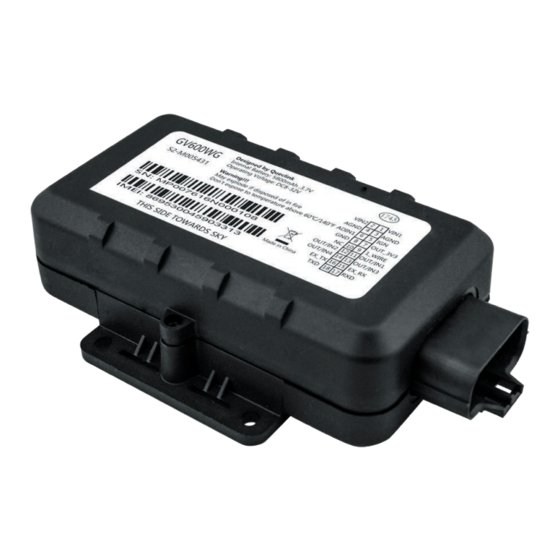
GV600WG Power &GND Cable [Optional accessory] 2.3. Interface Definition The GV600WG Tracker has an 18-pin interface connector which contains the connections for power, I/O, TTL, etc. The sequence and definition of the 18-pin connector are shown in the following figure: Figure 1. -
Page 9: Gv600Wg Standard Cable Color
Open drain output4 150mA max drive current EX_RX RS232 RX EX_TX RS232 TX UART RXD TTL UART TXD TTL 2.4. GV600WG Standard Cable Color Table 6. GV600WG Standard Cable Color Definition Definition Color Pin No. Connector Pin No. Color Definition... -
Page 10: Getting Started
GV600WG User Manual 3. Getting Started 3.1. Open and Close the Case Figure 2. Open the Case To open: Use a cross screwdriver to loosen the four screws and then lift the top case gently. To close: Align the top case with the bottom case and then tighten the four screws. -
Page 11: Install A Sim Card
SIM card is pushed into the SIM holder completely. Close the case. Figure 3. SIM Card Installation 3.3. Install the Internal Backup Battery and Close the Case GV600WG has an internal backup Li-ion battery (5200mAH). Figure 4. Backup Battery Installation 3.4. Power Supply Connection PWR (pin 1 or pin 2)/GND (pin 3 or pin 4) are the power input pins. -
Page 12: Ignition Detection
GV600WG User Manual Figure 5. External Power Supply Connection 3.5. Ignition Detection Table 7. Electrical Characteristics of Ignition Detection Logical Status Electrical Characteristics Active 5V to 32V Inactive 0V to 3V or open loop Figure 6. Typical Ignition Detection IGN (pin 5) is used for ignition detection. It is recommended to connect this pin to the “RUN”... -
Page 13: Digital Inputs
Figure 7. Typical Digital Input Connection 3.7. Analogue Inputs There is one analogue input on GV600WG, and the analogue input voltage range is from 0 to 32V. The following picture shows the recommended connection. Figure 8. Typical Analogue Input Connection Note: Pin 6 is a multifunction pin: it can be configured as an analogue input. -
Page 14: Digital Outputs
GV600WG User Manual 3.8. Digital Outputs There are four digital outputs on GV600WG. All are of open drain type and the maximum drain current is 150 mA. Each output has a built-in over current PTC resettable fuse. Figure 9. Digital Output Internal Drive Circuit Table 9. - Page 15 GV600WG User Manual Figure 11. Typical Connection with a LED Figure 12. Typical Connection with a Buzzer Figure 13. Typical Connection with Other Devices Note: Pay attention to the polarity of the relay if it is pre-installed with an internal flyback diode during connection.
-
Page 16: Device Status And Led
(Note 2) External power in and internal battery is charging. Fast flashing External power in and internal battery is fully charged. Figure 14. GV600WG LEDs on the Case Note: 1. LED cannot be configured. 2. Fast flashing: about 100ms ON/200ms OFF 3. -
Page 17: Temperature Sensor Interface
GV600WG User Manual 6.1. Temperature Sensor Interface Figure 15. Typical Connection with a Temperature Sensor 6.2. Serial Port/UART Interface There are two lines dedicated to the Serial Port/UART interface (TXD and RXD). TXD and RXD are standard TTL signal. Figure 16. Typical Connection with USB to TTL Serial Port 4. - Page 18 GV600WG User Manual 5. CE Declaration Hereby, Queclink Wireless Solutions Co., Ltd. declares that the radio equipment type GPS tracker is in compliance with Directive 2014/53/EU. The full text of the EU declaration of conformity is available at the following internet address: http://www.queclink.com/...
Need help?
Do you have a question about the GV600WG and is the answer not in the manual?
Questions and answers