
Related Manuals for Carl Goldberg Products Ultimate 10-300


Summary of Contents for Carl Goldberg Products Ultimate 10-300
- Page 1 U U l l t t i i m m a a t t e e U U l l t t i i m m a a t t e e 10-300 CARL GOLDBERG PRODUCTS, LTD. P.O. Box 818 Oakwood, GA 30566 Phone # 678-450-0085 www.carlgoldbergproducts.com ©2003...
-
Page 2: Limited Warranty
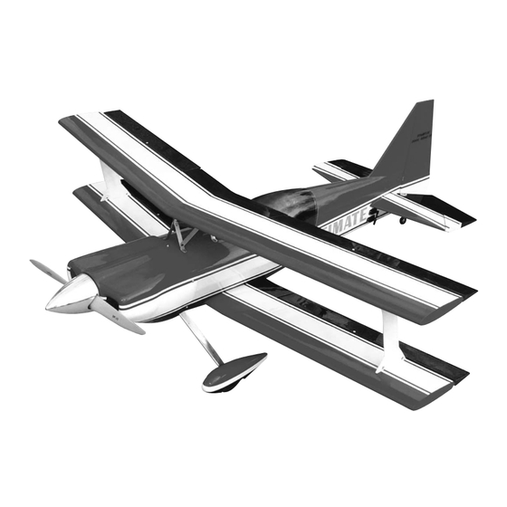
47302 LIMITED WARRANTY Carl Goldberg Products is proud of the care and attention that goes into the manufacture of parts for its model kits. The company warrants that for a period of 90 days, it will replace, at the buyers request, any part or materi- al shown to the company's satisfaction to have been defective in workman- ship or material at the time of purchase. - Page 3 30% Ultimate ARF 30% Ultimate ARF 3-D ARF 30% Ultimate ARF 3-D ARF Congratulations on your purchase of the Goldberg Ultimate ARF 3-D ARF. This is a very unique aircraft, with great 3-D capabilities. Every effort has been made to produce a lightweight, straight, easy to assemble aircraft. Because of its oversize control surfaces which are double beveled to allow for extreme throws, great care must be taken in the set-up and flying of this airplane.
-
Page 4: Parts Layout
30% Ultimate ARF Parts Layout 1.Fuselage 14.Cabane struts (6) pcs. 2.Removable cockpit 15.Firewall 3.Cowl 16.Hardware bag (not 4.Top wing shown) 5.Bottom wing 6.Rudder 7.Stabilizer 8.Elevator (2) 9.I-Struts (2) 10.Clear Canopy 11.Wheel pants (2) 12.Landing gear (2) 13.Aluminum angles (2) - Page 5 30% Ultimate ARF Hardware List Quantity per kit 6-32x3/4" Socket head screws 2 canopy hold down 8 I-Struts 4 cabane struts at fuselage 2 top wing mount at cabane 4 Landing gear aluminum angles 6-32x1/2" Socket head screws 4 cabane strut braces 2 Wheel pant mounts 6-32 lock nuts 4 cabane struts...
- Page 6 30% Ultimate ARF #6 flat washers 8 Control horns 4 Landing gear aluminum angles 5 cowl mount 4-40 golden clevis 8 aileron 4 elevator 4 rudder 4-40 jam nuts clevis retainers EZ connector body throttle screw snap nut 2-56x12" throttle push rod nylon snap link throttle 4-40x2-1/8"...
-
Page 7: Building Instructions
30% Ultimate ARF BUILDING Begin construction by locating the two 1/4-20 x 1” socket head bolt used INSTRUCTIONS to bolt the bottom wing on. Put the bottom wing in place and remove the Before starting to build this kit, we covering over the mount holes at the urge you to read through these trailing edge. - Page 8 30% Ultimate ARF When satisfied with the alignment, Remove the stab and using a sharp measure to make sure the stab is #11 blade, cut the covering about square and centered. Measurement A 1/8” inside the line you drew and should be the same on both sides and remove the covering.
- Page 9 30% Ultimate ARF Locate the two I-Struts and the eight 6-32x3/4” socket head cap screws. The I-Struts are identified left and right, top and bottom with small stickers. Take a straight pin and stick through the blind nut inside the fuselage to locate the holes for the struts.
- Page 10 30% Ultimate ARF With the I-Struts screwed in place, install the nuts on the screws that hold the top wing to the cabanes and tighten. Install the diagonal braces using the four 6-32x1/2” socket head cap screws and 6-32 aircraft lock nuts.
-
Page 11: Control Surfaces
30% Ultimate ARF Control Surfaces Locate the predrilled hole for the aileron, elevator, and rudder horns. Open the hole up with a 9/64” drill. Locate the 6-32 x 2” flat head screws, #6 washers, and 6-32 nuts. The rudder horn is a 3” long 6-32 threaded rod. -
Page 12: Landing Gear
30% Ultimate ARF Landing Gear Turn the plane upside down and draw a line down the center of the motor box and along the front edge of the gear plate Locate the two landing gear legs and the two 1”aluminum angles. Using four 6-32x3/4”... - Page 13 30% Ultimate ARF Align the gear so the outside hole will go through the center of the aluminum bracket. Align the inside edge of the gear parallel to the cen- ter line. It will be approximately 1/8” out side the line, don’t worry about the spacing.
-
Page 14: Wheel Pants
30% Ultimate ARF Locate the tail wheel bracket and align the bend in the strut at the rear of the fuselage. Center the mount on the fuselage and drill two 5/64” holes at the hole location. Harden the holes by using a couple of drops of thin CA in each hole. - Page 15 30% Ultimate ARF Drill a 1/2” hole at the dimple on the side with the wood block. If you have a forstner bit you can drill the 1/2” hole directly, if using a regular drill start with a small bit and work you way up slowly or grind out with a dremel too to prevent damaging the fiberglass.
-
Page 16: Cowl Mounting
30% Ultimate ARF Cowl Mounting Slide the cowl into position overlap- ping the fuselage 1/2”. Use masking tape to hold in place. Make sure the stripes are aligned on each side. Let the strips of paper be on the out side Slide the cowl into place and mark of the cowl. -
Page 17: Engine Mounting
30% Ultimate ARF Measure the engine length from the Engine mounting mounting plate to the thrust washer. Subtract this number from the length of the measurement of the cowl from former F1. That number is where you cut the motor box sides. You will need to add about 1/8”... - Page 18 30% Ultimate ARF dowels four Attach the motor box top covers places each side using the 10 #4x1/2” screws and #4 washers. Epoxy the firewall in place making sure to keep it square with the sides. Add the triangle top supports on both sides and the tri stock on the back side.
- Page 19 30% Ultimate ARF Shim the engine out if necessary to get approximately 1/8” clearance. Move the engine left or right and up and down till the spinner back plate matches the cowl. When satisfied with the fit, use a long drill to drill the motor mount holes.
- Page 20 30% Ultimate ARF Locate the fuel tank and hardware. There is a laser cut tank mount fur- nished with the plane. It is marked front. Assemble the tank with three lines. Take one of the pieces of brass tube and cut into two equal lengths. Bend the other tube so it will go to the top of the tank and fit into the raised portion of the tank.
-
Page 21: Servo Mounting
30% Ultimate ARF Locate the laser cut throttle servo mount and the two 3/8” x1” bass wood blocks. Epoxy the blocks to the plate with the triangles underneath. Place the tank between the holes and use the two 14” tie wraps to secure the tank to the mount. - Page 22 30% Ultimate ARF Locate the two servo cutouts on each side of the fuselage just under the stab. Remove the covering with a sharp knife. Install the two servos with the out- Locate the two 7” 4-40 pushrods and put shaft to the rear. You will need install nuts and clevises on each end.
- Page 23 30% Ultimate ARF Locate the four aileron servo cutouts in the bottom side of both wings. Remove the covering with a sharp knife. You will need four 14” servo lead extensions. There is a string located in each cutout to pull Locate the two switches, one radio the wire through to the center sec- one motor, just below the hatch rail...
-
Page 24: Final Setup
30% Ultimate ARF With hatch bolted in place, put wax paper between the turtle deck and hatch and between bottom of hatch and fuselage side to prevent gluing hatch to fuselage. If you do not have the hatch bolted in place when glu- ing the canopy on , it is very easy to Trim the clear canopy to fit hatch. - Page 25 30% Ultimate ARF minutes. Shut the engine down and check all your bolts, clevises, servos and linkage. Pull the wing off and check all the attach points, joints around the motor box, wing hold down block, firewall, and any other joints in the fuselage.
Need help?
Do you have a question about the Ultimate 10-300 and is the answer not in the manual?
Questions and answers