Table of Contents

Related Manuals for SCAN SCAN 60


Summary of Contents for SCAN SCAN 60
- Page 1 SCAN 60 and 61 INSTRUCTIONS FOR INSTALLATION AND USE T es te d & B ea v e r to n L ist ed b y O r e g o n U SA O M N I-T e s t L a bo r a t o r ie s , In c.
-
Page 2: Table Of Contents
Slide the air tube collar (pos.2) to the left, swing the air tube (pos.1) down and remove it........23 Replacement Part List SCAN 60 and 61..........................23 Creosote Formation and the Need for Removal ........................23 Door Glass................................... 24 Dimensions SCAN 60 and 61 ............................. -
Page 3: Introduction
We welcome you as a new owner of a SCAN wood-burning stove. In purchasing a SCAN stove you have joined the growing ranks of concerned individuals whose selection of energy systems reflects both a concern for the environment and aesthetics. The SCAN stove is one of the finest home wood stoves in the world over. -
Page 4: Safety Precautions
BUILD FIRES DIRECTLY UPON THE HEARTH INSIDE THE STOVE. DO NOT USE GRATES, IRONS, OR ANY OTHER METHOD TO ELEVATE THE FIRE. THE SCAN STOVES ARE NOT USABLE FOR FIREPLACE INSTALLATION. FOR USA ONLY: WHEN INSTALLING IN A MOBILE, THIS APPLIANCE MUST BE BOLTED TO THE FLOOR, HAVE OUTSIDE AIR SOURCE FOR COMBUSTION, AND NOT BE INSTALLED IN THE BEDROOM (PER H.U.D. -
Page 5: Installation
2. INSTALLATION Precaution If your SCAN stove is not properly installed, operated and maintained, a house fire may result. For your safety, follow all installation, operation and maintenance directions. Contact your local building officials about restrictions and installation requirements in your area. -
Page 6: The Floor
(top, sides, back, front, and under stove pipes) and any other material that can catch fire. NOTE: the floor protection need's only to be a standard ember protection. Floor pad at Parallel Installation Model Floor protection Scan 60 16” 9,5” 8” 43,8” 33,7”... -
Page 7: Floor Pad At Corner Installation
Corner installation Floor pad at Corner Installation Model Floor protection Scan 60 16” 7,5” 73,8” 104,5” Scan 60 Canada 1975 2794 Scan 61 16” 7,5” 68” 96” Scan 61 Canada 1983 2804 In a rear vent installation the floor protection must also extend under the stovepipe a minimum of 2”... -
Page 8: Combustible Wall Clearance For Top Vent Installation
Combustible Wall Clearance for Top Vent Installation If the stove is to be placed at side and back walls of combustible materials the following clearances must be kept Parallel and corner installation Model Connector pipe Scan 60 Single wall 10.5 13.5 Scan 60 Canada... -
Page 9: Combustible Wall Clearance For Rear Vent Installation
If the stove is to be placed at side and back walls of combustible materials the following clearances must be kept: Rear outlet through wall Model Connector pipe Scan 60 & 61 Single wall 5.25 Scan 60 & 61 Canada Single wall Refer to the manufacturer’s instructions concerning installation of listed single wall connector pipe,... -
Page 10: Alcove Installation Requirements
Whenever the stove is placed in a location where the ceiling height is less than 7’ tall, it is considered an alcove installation. Because of the reduced height, the special requirements listed below must be met. Alcove installation: Model Connector pipe Scan 60 Double wall 12.5 Scan 60 Canada Double wall... -
Page 11: Mobile Home Installation: Us Only
Mobile Home Installation: US only In addition to standard installation the following requirements are mandatory for installation in a mobile home. The stove must be permanently bolted to the floor of the mobile home using the floor screws provided. Note: If the composition of the manufactured (mobile) home floor is of light particleboard construction, you will be required to secure the stove with regular hex head bolts and nuts. -
Page 12: Outside Air Requirements
Draft Requirements SCAN stoves are only one component of the total system. The venting system is equally important for achieving the required flow of combustion air to the firebox and for safely removing unwanted combustion by-products from the appliance. -
Page 13: Chimney Installation
Chimney Installation: Do not connect this unit to a chimney flue serving another appliance. Do not connect to any air distribution duct or system. The stoves are listed for installation as a vertically top or rear vented stove using a listed class A (UL103HT) for Canada (CAN/ULC-S629) factory built chimney exiting through the ceiling/attic/roof. -
Page 14: Chimney Connection
The chimney connector is ether a single or double walled pipe, depending on the type of installation, used to connect the stove to the chimney. For use with the SCAN woodstoves the chimney connector MUST be 6” in diameter, with a minimum thickness of 24 gauge black steel or 26 gauge blued steel. -
Page 15: Rear Vent Installation
From the factory the stove is prepared for top mounting of the flue collar, but all SCAN stoves have an optional flue outlet, therefore the flue collar can be fitted either on the top or at the rear as required. -
Page 16: Combustible Wall Chimney Connector Pass-Throughs
Combustible Wall Chimney Connector Pass-Throughs. Method A. 12” (304.8 mm) Clearance to Combustible Wall Member: Using a minimum thickness 3.5” (89 mm) brick and a 5/8” (15.9 mm) minimum wall thickness clay liner, construct a wall pass-through. The clay liner must conform to ASTM C315 (Standard Specification for Clay Fire Linings) or its equivalent. -
Page 17: Chimney Height Requirements
NOTES: 1. Connectors to a masonry chimney, excepting method B, shall extend in one continuous section through the wall pass-through system and the chimney wall, to but not past the inner flue liner face. 2. A chimney connector shall not pass through an attic or roof space, closet or similar concealed space, or a floor, or ceiling. -
Page 18: Instructions For Use
Baffle Plates The SCAN stoves have two baffle plates that must be installed in the upper firebox. When in the proper position, the rear edges of the baffle plates should touch the back wall of the firebox. See the maintenance section of this manual for additional information on Removing Baffle plates for Cleaning on page 20. -
Page 19: Ceramic Packing Cord
Ceramic Packing Cord These stoves are equipped with a ceramic packing cord to ensure the tightness of the doors and the glasses. This packing cord is a wearing part and must be changed from time to time. Please consult your authorized dealer in this case. Protected Wall Reduced Clearances Local codes in some areas will allow reduced clearances when the stove is installed adjacent to a protected wall system. -
Page 20: Operation
Your SCAN freestanding wood stove is designed for burning dry, natural, well-seasoned wood only. (If your wood supply is not seasoned, ask your authorized SCAN dealer where to obtain seasoned fuel in your area). Wood should be stored in a dry place for at least one year before being used for fuel. -
Page 21: Maintenance
5. MAINTENANCE Ash Disposal and Removal CAUTION: Be sure the fire is out and the stove is cold before removing ashes! Be careful when you empty the stove for the ashes. There may be embers left up to 24 hours after the stove was last used. -
Page 22: Removing Baffle For Cleaning
Removing Baffle for Cleaning. Be sure the fire is out and the stove is cold before removing baffle plate. Be cautions with handling the plates because the plates are made of a delicate material; which easily broke if not handle with care. -
Page 23: Slide The Air Tube Collar (Pos.2) To The Left, Swing The Air Tube (Pos.1) Down And Remove It
Slide the air tube collar (pos.2) to the left, swing the air tube (pos.1) down and remove it. Replacement Part List SCAN 60 and 61. Caution: Use only original SCAN replacement part. Do not use substitute materials. Replacement part Part #... -
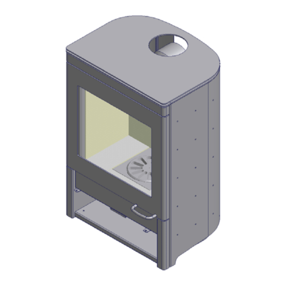
Page 24: Door Glass
Be careful not to abuse the glass by striking or slamming the door shut. Do not operate the stove with broken glass. If the glass breaks then replace it promptly. Use only replacement packing cord listed for the door, glass and ash drawer. Dimensions SCAN 60 and 61 SCAN 61 SCAN 60... -
Page 25: Troubleshooting
6. TROUBLESHOOTING Smoke: - Insufficient chimney draught! - Check if the chimney has the right dimension. - Check if the smoke pipe or chimney is blocked. - Check if the chimney has the right height compared to the surroundings. - Wood with excessive moisture content. The wood burns too fast: - Are the air valves adjusted correctly according to the instructions? - Is the smoke deflector plate placed correctly? -
Page 26: Warranty Conditions For Scan Wood Burning Products
7. WARRANTY CONDITIONS FOR SCAN WOOD BURNING PRODUCTS All SCAN wood stoves; inserts and fireplaces are subject to a strict quality control, before they are shipped to the customer and end user. However, should an error occur, we back all SCAN wood burning stoves, inserts, and fireplaces with an extensive five years limited warranty. -
Page 27: Epa Sticker
8. EPA Sticker...
Need help?
Do you have a question about the SCAN 60 and is the answer not in the manual?
Questions and answers