
Related Manuals for SCAN 68 Series


Summary of Contents for SCAN 68 Series
- Page 1 UK - ASSEMBLY AND INSTRUCTIONS MANUAL SCAN 68 ASSEMBLY AND INSTRUCTIONS MANUAL SCAN 68...
- Page 2 CONGRATULATIONS ON YOUR NEW SCAN WOOD-BURNING STOVE You have purchased a product by one of Europe’s leading manufacturers of wood-burning stoves, and we are sure that you will have years of pleasure from your purchase. To make the best possible use of your stove, it is important that you follow our advice and instructions.
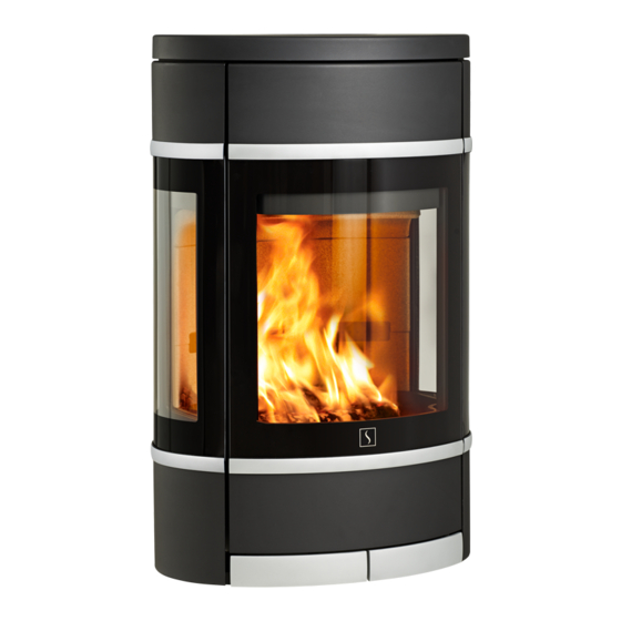
- Page 3 With side windows With side windows Black mouldings Aluminium mouldings Black mouldings Aluminium mouldings Black mouldings Aluminium mouldings Scan 68-13 LB Scan 68-14 LB Scan 68-13 Scan 68-14 Scan 68-13 HT Scan 68-14 HT Low Base Low Base Steel sides...
-
Page 4: Table Of Contents
Mounting of external air supply on the wall fitting Safety distance Fitting natural stone Distance to flammable materials, Mounting of high top Distance to firewall Wall mounting kit for Scan 68 with high top ¬ INSTRUCTIONS FOR USE CB-technology (Clean Burn) Handle for riddling grate Baffle plate... -
Page 5: Technical Data
Any changes made to the product by the dealer, fitter or user could result in the product and safety functions not functioning as intended. The same applies to the fitting of accessories or extra equipment not supplied by Scan A/S. This could also be the case if parts that are necessary for the operation and safety of the stove are dismantled or removed. -
Page 6: Dimension
DIMENSION SCAN 68-1, 68-2, 68-7 AND 68-8 (WALL HUNG MODEL) Centre rear outlet Height to the beginning of the connecting piece at top outlet Centre of fresh air intake All measurements are in millimeters DIMENSION SKETCH SCAN 68-3, 68-4, 68-9 AND 68-10 (PEDESTAL) - Page 7 DIMENSION SKETCH SCAN 68-5, 68-6, 68-11 AND 68-12 (PORTAL) Centre rear outlet Height to the beginning of the connecting piece at top outlet Centre of fresh air intake All measurements are in millimeters...
- Page 8 DIMENSION SKETCH SCAN 68-13 AND 68-14LB (LOW BASE) Centre rear outlet Height to the beginning of the connecting piece at top outlet Centre of fresh air intake All measurements are in millimeters DIMENSION SKETCH 68-13 AND 68-14 (STEEL SIDES) Centre rear outlet...
- Page 9 DIMENSION SKETCH SCAN 68-13 AND 68-14 HT (HIGH TOP) Centre rear outlet Height to the beginning of the connecting piece at top outlet Centre of fresh air intake All measurements are in millimeters...
- Page 10 DIMENSION SKETCH SCAN 68-15 AND 68-16 LB (SOAPSTONE + LOW BASE) Centre rear outlet Height to the beginning of the connecting piece at top outlet Centre of fresh air intake All measurements are in millimeters DIMENSION SKETCH SCAN 68-15 AND 68-16 (SOAPSTONE)
- Page 11 DIMENSION SKETCH SCAN 68-15 AND 68-16 HT (SOAPSTONE + HIGH TOP) Centre rear outlet Height to the beginning of the connecting piece at top outlet Centre of fresh air intake All measurements are in millimeters...
-
Page 12: Type Plate
TYPE PLATE All Scan wood-burning stoves are fitted with a type plate that specifies the approval standards and the distance to flammable materials. The type plate is located at the rear of the stove. Typeplates Wall mounted room heater fired by solid fuel... -
Page 13: Assembly
PRODUCT REGISTRATION NUMBER All Scan wood-burning stoves are provided with a product registration number. You will always need to quote this number when contacting your dealer or Scan A/S. The product registration number is located at the rear of the stove. -
Page 14: Removal Of Packaging
REMOVAL OF PACKAGING Check that the stove is not damaged before starting to install it. Please remove protection Remove the two screws in the wood compartment and lift the stove off the pallet The plastic plugs are mounted in the transport safety holes Pull back and lift... -
Page 15: Mounting Of The Burn Chamber On The Pedestal Basel
MOUNTING OF THE BURN CHAMBER ON THE PEDESTAL BASEL The stove is delivered with the screws mounted. When the stove has been placed on the base, These must be removed before mounting the base the four screws must be remounted... -
Page 16: Mounting Of The Burn Chamber On The Portal Basel
MOUNTING OF THE BURN CHAMBER ON THE PORTAL BASEL The stove is delivered with the screws mounted. When the stove has been placed on the base, These must be removed before mounting the base the four screws must be remounted... -
Page 17: Mounting Of The Storage Door For The Portal Unit
MOUNTING OF THE STORAGE DOOR FOR THE PORTAL UNIT (ACCESSORY) Dismount the door Remove the four screws under the stove before placing the door assembly Carefully push the door First mount the four Remount the door assembly in from behind screws at the top The 4 outer screws at the bottom are easily tightened Rejust... -
Page 18: Mounting Of Wall-Hung Model
There must be a distance of at least 6 mm between the first section and the flange on the flue collar. Please consult a specialist. Scan A/S disclaims all liability for the installation of wall-hung wood-burning stoves. Must be removed, also in the heat shield, for wall fitting... -
Page 19: Mounting Of The Wall Fitting On The Stove
In order to mount the wall fitting to a chimney made of Leca-blocks you need 6 pcs. FBS 8x70/5 US Leca screws. The test report can be required at Scan A/S When the two screws have been removed, you can lift the guide plate and put the fitting underneath... - Page 20 Draw a vertical line on the wall Measure from the vertical line and drill the holes (you can use a spirit level). Use this line for the mounting of the wall fitting Mount the two guide blocks Use the guide blocks to hold the wall fitting while adjusting it.
- Page 21 Mount screw and disc. When the stove is in position, mount the two screws in the bottom and the loose decor grate on the top If you want an external air supply, it should be mount- ed now. (See instructions in this manual) The two screws under the stove must be removed, before lifting the stove up on the wall fitting If you want a rear outlet, see page 27 in this manual...
-
Page 22: Removal Of The Self-Closing Door Spring
REMOVAL OF THE SELF-CLOSING DOOR SPRING The stove is born with a spring that makes the door close automatically. This spring can easily be removed with a nipper. Bottom view MOUNTING OF EXTERNAL AIR SUPPLY ON THE WALL FITTING If you do not want an external air supply, it is not necessary to mount the duct tube or the connecting piece. If you want external air supply from the bottom, mount the connecting piece If you DO NOT want an external air supply, remove the... -
Page 23: Fitting Natural Stone
FITTING NATURAL STONE Scan 68-15 and Scan 68-16 are supplied with loose pieces of natural stone that are fitted to the sides of the stove. Natural stone is made from a natural material and consequently its pattern and shape may vary. -
Page 24: Mounting Of High Top
If you choose to connect the stove with an elbow pipe or a rear outlet, the stove must be mounted to the wall behind the oven us- ing a special wall mounting kit. This kit can be purchased from your local Scan dealer. For fitting, see instructions in this manual. -
Page 25: Wall Mounting Kit For Scan 68 With High Top
If you choose to connect the stove with an elbow pipe or a rear outlet, the stove must be mounted to the wall behind the oven using a special wall mounting kit. This kit can be purchased from your local Scan dealer. -
Page 26: Heat-Storage Stone
Fixing hole for fastening the safety wire in the high top with rear outlet. (1) Fixing hole for fastening the safety wire in the high top with elbow pipe. (2) HEAT-STORAGE STONE (ACCESSORY) Heat-storage stones are made from a special material with a high heating capacity. The stones are heated up during the firing and gives off the heat again after the firing, which means that the stove stays warm for a longer time. -
Page 27: Height Adjustment Of Stove
HEIGHT ADJUSTMENT OF STOVE The Scan 68 has four adjustment screws under the stove. Use the adjustment screws and the adjustment key (Accessories) to get the stove to stand straight and level. If the floor plate is used, the stove must be adjusted so that the plate can be placed under the front of the stove. -
Page 28: Existing Chimney And Pre-Fabricated Element Chimney
EXISTING CHIMNEY AND PRE-FABRICATED ELEMENT CHIMNEY If you intend to connect your stove to an existing chimney, it makes sense to contact an authorised Scan dealer, or a local chim- ney sweep, for advice. These experts will also let you know if your chimney needs renovating. -
Page 29: Load-Bearing Foundation
floor around the stove. Your local Scan dealer can advise you on regulations concerning protection of flammable materials in the vicinity of your stove. The floor plate’s function is to protect the floor and flammable material against any sparks that may occur. A floor plate can be made of steel or glass, but the stove can also be erected on clinker concrete, natural stone or similar materials. -
Page 30: Distance To Flammable Materials
DISTANCE TO FLAMMABLE MATERIALS, , SHOWN WITH UN-INSULATED FLUE PIPE 45° Corner installation Parallel rear wall installation A: 317 mm A: 100 mm A: 449 mm A: 650 mm A: 650 mm A: 400 mm B: 350 mm B: 802 mm B: 567 mm B: 750 mm B: 750 mm... -
Page 31: Distance To Firewall
DISTANCE TO FIREWALL 110 mm brick, 50 mm JØTUL Firewall or other material with a corresponding insulation ability. The indicated distances are valid for insulated as well as un-insulated smoke pipes. A: 1000 mm A: 600 mm B: 1000 mm *1000/**1000 B: 1200 mm *1100/**1200... -
Page 32: Instructions For Use
INSTRUCTIONS FOR USE CB-TECHNOLOGY (CLEAN BURN) The stove is equipped with CB technology. In order to ensure optimal combustion of gases released during the combustion process, air passes through a specially developed system of channels. The heated air is conducted into the combustion chamber through the holes in the rear lining of the combustion chamber and at the baffle plates. -
Page 33: Handle For Riddling Grate
HANDLE FOR RIDDLING GRATE The stove is equipped with a riddling grate that - when activated - empties the ashes from the burn chamber into the ash tray. ¬ The riddling grate must be half open during the firing. REFUELING ON TO A LOW FIRE BED If there is insufficient burning material in the fire bed to light a new fuel charge, excessive smoke emission can occur. -
Page 34: Fresh Air Intake
National and local building regulations must be followed with regard to connection of a fresh air intake. NOTE: WHEN CONNECTING THE SCAN 68 LOW BASE WITH A FRESH AIR INLET, WE RECOMMEND THAT YOU USE A SHORT, 158962 ANGLED CONNECTION PIECE BECAUSE OF THE LIMITED SPACE IN THE BASE. -
Page 35: Instructions For Heating
LIGHTING We recommend the use of fire lighters, or similar products, which are available from your Scan dealer. Using fire lighters helps light the wood more quickly and keeps the combustion process clean. See our video about correct firing on www.scan.dk or scan the QR-code. Please note that this... -
Page 36: Continuous Operation
CONTINUOUS OPERATION It is important to obtain as high a temperature as possible in the combustion chamber. This results in best possible use of the stove and fuel, as well as achieving clean combustion. In this way you will avoid build-up of soot on the combustion chamber lining and glass pane. -
Page 37: Selecting Wood/Fuel
CHIMNEY FIRE In the event of a chimney fire, keep the stove door, the ash container, and all dampers on the stove closed. In an emergency, call the fire service. ¬ We recommend that you get a chimney sweep to check the chimney before using the stove again. HANDLING FUEL SELECTING WOOD/FUEL You can use any type of wood as fuel. - Page 38 CHECKING THE STOVE Scan A/S recommends that you check your stove thoroughly after sweeping/cleaning. Check all visible surfaces for cracks. Check that all joints are tight and that the gaskets are correctly seated. Worn or deformed gaskets should be replaced.
- Page 39 Mount skamol plate 2a and 2b Mount skamol plate 3a and 3b Mount skamol plate 4a and 4b When skamol plates 1-4 are inserted, it should look like this. Mount skamol plate 5a and 5b Make sure that the two baffles are placed identically Mount the baffle plate (6) with the accompanying pin (7)
- Page 40 Clean your wood-burning stove by wiping it down with a dry, lint-free cloth. If the paint finish gets damaged, you can purchase repair paint in spray form from your Scan dealer. As slight differences in color shade are possible, we recommend you spray a larger area to achieve a natural blend. For best results, apply repair spray when the stove is warm enough for you to just keep your hand on it, but no hotter.
- Page 41 TROUBLESHOOTING SMOKE ESCAPING ¬ Damp wood ¬ Chimney not drawing properly ¬ Chimney is not properly dimensioned for the stove ¬ Check if the smoke gas pipe/chimney are blocked ¬ Is the chimney the right height for its surroundings? ¬ Vacuum in room ¬...
- Page 42 You must quote your stove‘s product registration number when you contact us or your authorized Scan dealer with a warranty claim. The warranty covers all parts which in the opinion of Scan A/S require repair or replacement due to manufacturing or construc- tion error The warranty applies to the original purchaser of the product only, and is not transferable (except on prior sale).
- Page 43 MOUNTING THE UK-SCREW This screw (M5 x 10) must be placed as shown in the pictures, to prevent secondary air control can be closed completely. After mounting the UK screw the type plate must be changed with the one delivered with this manual. NOTE: After mounting the UK Screw Open both, secondary and primar air control to mount the screw.
- Page 44 Product registration number Quote this number at all enquiries Edition: UK 90068500 SCAN A/S Glasvænget 3-9 DK-5492 Vissenbjerg www.scan.dk 20.08.2018...
Need help?
Do you have a question about the 68 Series and is the answer not in the manual?
Questions and answers