Table of Contents
Advertisement
Quick Links
Advertisement
Table of Contents

Related Manuals for Advantech PCM-3335


Summary of Contents for Advantech PCM-3335
-
Page 2: Fcc Statement
FCC STATEMENT THIS DEVICE COMPLIES WITH PART 15 FCC RULES. OPERA- TION IS SUBJECT TO THE FOLLOWING TWO CONDITIONS: (1) THIS DEVICE MAY NOT CAUSE HARMFUL INTERFER- ENCE. (2) THIS DEVICE MUST ACCEPT ANY INTERFERENCE RECEIVED INCLUDING INTERFERENCE THAT MAY CAUSE UNDESIRED OPERATION. - Page 3 This document is copyrighted, 1995, 1996, by AAEON Technology Inc. All rights are reserved. AAEON Technology Inc. reserves the right to make improvements to the products described in this manual at any time without notice. No part of this manual may be reproduced, copied, translated or transmitted in any form or by any means without the prior written permission of AAEON Technology Inc.
- Page 4 Before you begin installing your card, please make sure that the following materials have been shipped: • 1 PCM-3335 CPU card • 1 5-pin PC-AT keyboard adapter • 1 Hard disk drive (IDE) interface cable (40 pin) • 1 Floppy disk drive interface cable (34 pin) •...
-
Page 5: General Information
1 General Information ........1 Introduction ................2 Specifications ................3 2 Installation ........... 5 Jumpers and connectors ............6 Board Layout ................7 Setting jumpers ..............8 Safety precautions ..............9 IDE hard drive connections (HARD CON.) ...... 10 Connecting the hard drive ............ -
Page 6: Table Of Contents
3 AMIBIOS Setup ..........21 General information ............22 Starting AMIBIOS setup ............22 AMIBIOS main menu ............22 Standard Setup ..............23 Advanced Setup ..............24 Advanced Chipset Setup ............27 4 SVGA Setup ..........31 Simultaneous display mode ..........32 Sleep mode ................ -
Page 8: General Information
This chapter provides background information for the PCM-3335. Sections include: • Card specifications • Board layout Chapter 1 General Information... - Page 9 With its industrial grade reliability, the PCM- 3335 can operate continuously at temperatures up to 140º F (60º C). The PCM-3335 is specially designed as a compact all-in-one CPU card which incorporates a PC/104 connector into its design, making non-passive backplane SBC applications possible.
- Page 10 40MHz 80386SX Bus Interface PC/104 (ISA) bus 16-bit Data Bus Processing Ability 32-bit 2MB or 4MB RAM memory Support for system and video BIOS up to 256KB in Shadow RAM 32KB blocks Display Memory 512KB DRAM chip on board Supports up to two IDE (AT bus) HDDs IDE HDD interface FDD interface Supports up to two FDDs...
- Page 11 PCM-3335 User's Manual...
-
Page 12: Installation
This chapter explains set up procedures for the PCM-3335 hardware, including instructions on setting jumpers and connecting peripherals, switches and indicators. Be sure to read all safety precautions before you begin the installa- tion procedure. Chapter 2 Installation... -
Page 13: Jumpers And Connectors
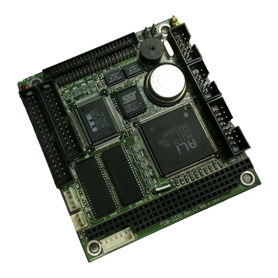
COM2 COM2 (RS-232) COM1 COM1 (RS-232) VGA CON. VGA connector PC/104 (64-pin) PC/104 (40-pin) PS2 KB External keyboard connector CN4, CN6 Power connector HD-LED HDD LED connector RST SW. Reset switch connector CLEAR CMOS Clear CMOS connector PCM-3335 User's Manual... - Page 14 PC/104 Interface PS2 KB. DRAM DRAM M6117B BAT. Flash BIOS CLEAR CMOS FLAT PANEL CON. FLOPPY CON. HD-LED HARD CON. RST SW. PRINTER PORT Chapter 2 Installation...
-
Page 15: Setting Jumpers
If you have any doubts about the best hardware configuration for your application, contact your local distributor or sales represen- tative before you make any changes. Generally, you simply need a standard cable to make most connections. PCM-3335 User's Manual... - Page 16 Warning! Always completely disconnect the power cord from your chassis whenever you are working on it. Do not make connections while the power is on because sensitive electronic components can be damaged by the sudden rush of power. Only experienced electronics personnel should open the PC chassis.
- Page 17 You can attach two Enhanced Integrated Device Electronics hard disk drives to the PCM-3335's internal controller. The card comes with a 40-pin flat cable. Wire number 1 on the cable is red or blue, and the other wires are gray.
- Page 18 The following table lists the pin numbers and their respective signals: Signal Signal Reset N.C. N.C, IORDY BALE N.C. -I/O CS16 N.C. -ACT Chapter 2 Installation...
- Page 19 You can attach up to two floppy disks to the PCM-3335's on-board controller. You can use any combination of 5¼" (360 KB and 1.2 MB) and/or 3½" (720 KB, 1.44 MB, and 2.88 MB) drives. The PCM-3335 CPU card comes with a 34-pin daisy-chain drive connector cable.
- Page 20 Normally, the parallel port is used to connect the card to a printer. The PCM-3335 includes an on-board parallel port, accessed through PRINTER PORT, and a 26-pin flat-cable connector. The CPU card comes with an adapter cable, which lets you use a traditional DB-25 connector.
-
Page 21: Power Supply Connector
In single board computer (non-passive backplane) applications, you will need to connect power directly to the PCM-3335 board using CN4 and CN6. This connector is fully compatible with the standard PC power supply connectors. See the following table for its pin assignments:... - Page 22 The PCM-3335 CPU card's SVGA connector (VGA CON.) with PCI bus supports monochrome display as well as high resolution color displays. The card also features an LCD connector (FLAT PANEL CON.), which allows you to connect various flat panel displays. The following table lists their pin assignments:...
- Page 23 Function Function SIGNAL GND H-SYNC GREEN CHASSIS GND SIGNAL GND V-SYNC BLUE CHASSIS GND CHASSIS GND PCM-3335 User's Manual...
- Page 24 The PCM-3335 board provides one keyboard connector. A 5-pin connector (PS2 KB.) supports passive backplane applications. Function K.B. clock K.B. data N.C. +5 V Chapter 2 Installation...
- Page 25 The PCM-3335 offers two serial ports (RS-232). These ports let you connect to serial devices (a mouse, printers, etc.), or a commu- nication network. Signal You can connect an external switch to easily reset your computer. This switch restarts your computer as if you had turned off the power then turned it back on.
- Page 26 You can connect a LED to indicate that an IDE device is in use. The pin assignments for this jumper are as follows. Function -R/W IDE Pull high You can connect an external switch to clear CMOS. This switch closes CLEAR CMOS and turns on the power, at which time the CMOS setup can be cleared.
- Page 27 PCM-3335 User's Manual...
- Page 28 This chapter describes how to set BIOS configuration data.
-
Page 29: Amibios Setup
Auto-configuration with Optimal Settings Auto Configuration with Fail Safe Settings Save Settings and Exit Exit Without Saving Standard CMOS setup for changing time, date, hard disk type, etc. ESC: Exit :Sel F2/F3: Color F10: Save and Exit 22 PCM-3335 User's Manual... - Page 30 The AMIBIOS Setup options described in this section are selected by choosing the Standard CMOS Setup from the AMIBIOS Setup main menu selection screen, as shown below. The Standard Setup screen appears: AMIBIOS SETUP — STANDARD CMOS SETUP (C) 1995 American Megatrends, Inc. All Rights Reserved Date (mm/dd/yyyy): Wed Aug 21, 1996 Time (hh/mm/ss):...
- Page 31 E000, 32K Shadow Disabled E800, 32K Shadow Disabled Onboard IDE Enabled Onboard FDC Enabled Onboard Serial Port 1 Onboard Serial Port 2 Onboard Parallel Port Parallel Port Mode ECP DMA DMA 3 Parallel Port IRQ IRQ 7 24 PCM-3335 User's Manual...
- Page 32 The following is a list of options offered by Advanced Setup. Advanced Setup Options Function Options Quick Boot Disable Enable BootUp Num-Lock BootUp Sequence C:, A: A:, C: Floppy Drive Swap Disable Enable Mouse Support Disable Enable System Keyboard Disable Enable Primary Display VGA/EGA...
- Page 33 Onboard FDC Disable Enable Onboard Serial Port 1 Disable Onboard Serial Port 2 Disable Onboard Parallel Port Disable Parallel Port Mode EPP & ECP ECP DMA DMA 3 DMA 1 Parallel Port IRQ IRQ 7 IRQ 5 26 PCM-3335 User's Manual...
- Page 34 Select the Advanced Chipset Setup from the AMIBIOS Setup main menu to enter the Chipset Setup. The standard options of the Chipset Setup are shown in the following table. A detailed list of available options is also provided. AMIBIOS SETUP — ADVANCED CHIPSET SETUP (C) 1995 American Megatrends, Inc.
- Page 35 Disable Enable ISA Memory High Speed Disable Enable ISA Write cycle end Insert Wait Disable Enable I/O Recovery Disable Enable I/O Recovery Period Disable Enable On-Chip I/O Recovery Disable Enable 16-bit ISA Insert Wait Disable Enable 28 PCM-3335 User's Manual...
- Page 36 1) Select this option from the main menu 2) Enter the Password and Press <Enter> 3) Retype the Password and Press <Enter> If you forget the user's password, please contact your distributor for another password which you can use to enter the BIOS setup and change your own password.
- Page 37 30 PCM-3335 User's Manual...
- Page 38 The PCM-3335 features an on-board flat panel/VGA interface. This chapter provides instructions for installing and operating the software drivers on the included display driver diskette.
-
Page 39: Sleep Mode
Both CRT and panel displays can be used simultaneously. The PCM-3335 can be set in one of three configurations: on a CRT, on a flat panel display, or on both simultaneously. The system is initially set to simultaneous display mode. -
Page 40: Vesa 1.2
The drivers support the following applications using the filena- mes and resolutions listed: Application Filename Resolution Colors Windows 3.1 LINEAR4.DRV 640x480 800x600 1024x768 LINEAR8.DRV 640x480 800x600 1024x768 LINEAR16.DRV 640x480 LINEAR24.DRV 640x480 AutoCAD R12 RCTURBOC.EXP 640x480 800x600 1024x768 640x480 800x600 1024x768 640x480 640x480 640x480... -
Page 41: Word 5.0
The display driver diskette contains drivers for several versions of certain applications. You must install the correct version in order for the driver to work properly so make sure you know which version of the application you have. PCM-3335 User's Manual... - Page 42 These drivers are designed to work with Microsoft Windows 3.1. You may install these drivers through Windows or in DOS. Step 1: Install Windows as you normally would for a VGA display. Run Windows to make sure that it is working correctly. Step 2: Place the display driver diskette in drive A.
- Page 43 Setup, repeating steps 4 and 5 from the previ- ous page. Besides the special display drivers marked by an asterisk (*), you should be able to use the following standard drivers: 640x480, 16 colors Super VGA 800x600, 16 colors PCM-3335 User's Manual...
- Page 44 Special panning drivers are provided to allow high-resolution modes to be displayed on a flat panel or CRT. These drivers will show a section of a larger screen and will automatically pan, or scroll, the screen horizontally and vertically when the mouse reaches the edge of the display.
-
Page 45: Driver Installation
Select Configure Video Display. In Display Device Configura- tion choose Select Graphics Board/Resolution. Then choose Select Display Graphics Board. After choosing a graphics board, go to Select Display Resolution. After selecting the display resolution, save the new configuration, and return to the main menu. PCM-3335 User's Manual... - Page 46 This menu allows you to modify: Number of AutoCAD Command Lines Font Size 6x8/8x8/8x14/8x16/12x20/12x24 Dual Screen Enable/Disable User Interface Configuration Double Click Interval Time BP Button BP Highlight Patt Line/Xor Rect/Both BP Refresh Enable/Disable BP Cache Enable/Disable This menu allows you to modify: Display List Enable/Disable Drawing Cache...
- Page 47 Step 4: After the selection of the appropriate VGA display driver, you will need to exit this menu and return to the Main Lotus Installation Menu. Do this by selecting Return To Menu. Step 5: At the Lotus Installation Menu, select Save Changes. PCM-3335 User's Manual...
- Page 48 Step 6: At this point the Installation Menu will prompt you for the name of your new Lotus configuration file. The Lotus system will prompt you with the default value — 123.SET, but you may want to use a filename that indicates the resolution of its driver. For example, if you installed the 132 column by 25 line driver, you could name this driver 132X25.SET, or if you installed the 80 by 50 driver, you may want to call the file 80X50.SET.
- Page 49 Make sure that your monitor is capable of displaying these high resolution modes before enabling them. NOTE: If the video BIOS already supports VBE extended video modes, DO NOT use this driver. Run the VTEST.EXE program to see if the video BIOS supports the VBE modes. PCM-3335 User's Manual...
- Page 50 These drivers are designed to work with Microsoft Word 5.0 and 5.5. If you have already installed Word on your computer, go to Step 2 to install the new video driver. Step 1: Install Word as normal. Step 2: After you complete the Word installation, place the display driver diskette into drive A.
- Page 51 Press <ESC> followed by Y to exit to DOS. Step 2: Start WordPerfect, and press <SHIFT>+<F1> to enter the setup menu. Select D for Display and G for Graphics Screen Type, and then choose the desired Chips VGA resolution. PCM-3335 User's Manual...
- Page 52 Follow these instructions to configure WordPerfect 5.0 for 132 column text mode: Step 1: To use the SETCOL program to set 132 columns and 25 rows, type the following command: SETCOL 132, 25 <ENTER> Step 2: Start WordPerfect. The program will detect the number of rows and columns automatically.
- Page 53 PCM-3335 User's Manual...
-
Page 54: Installing Pc/104 Modules
This appendix gives instructions for installing PC/104 modules. - Page 55 30 KHz A/D Module • PCM-3724 48-channel DIO Module • PCM-3910 Breadboard Module Installing these modules on the PCM-3335 is a quick and simple operation. The following steps indicate how to mount the PC/104 modules: Step1 Remove the PCM-3335 from your system paying particular attention to the safety instructions already mentioned above.
-
Page 56: A Installing Pc/104 Modules
Step4 Mount the PC/104 module onto the CPU card. Do this by pressing the module firmly but carefully onto the mounting connectors. Step5 Secure the PC/104 module onto the CPU card using the four mounting spacers and screws. P C / 1 0 4 M o u n t i n g S u p p o r t Male Male... - Page 57 3 . 5 7 5 0 . 2 0 0 0 . 2 0 0 0 . 2 0 0 3 . 3 5 0 3 . 5 5 0 PC/104 module dimensions (inches ±5 %) 50 PCM-3335 User's Manual...
-
Page 58: Configuring Various Lcd Display
This appendix gives instructions for configuring various LCD displays. - Page 59 Follow the instructions below to integrate an LCD VGA BIOS into the PCM-3335 system BIOS. 1. Combine the VGA BIOS with the system BIOS following the instructions at the DOS prompt. DEBUG ; DOS utility program SBC-355.ROM <ENTER> 4000:0 <ENTER>...
Need help?
Do you have a question about the PCM-3335 and is the answer not in the manual?
Questions and answers