Panasonic KX-TD816 Installation Manual
Digital super hybrid system
Hide thumbs
Also See for KX-TD816:
- Installation manual (502 pages) ,
- Programming manual (443 pages) ,
- User manual (388 pages)
Table of Contents
Advertisement
Panasonic Telephone Systems
KX-TD1232
KX-TD816
Panasonic KX-TD1232, KXTD1232, KX TD1232, TD1232, KX-TD816, KXTD816, KX TD816, TD816
Thank you for purchasing this Panasonic Model KX-TD816/KX-TD1232, Digital Super Hybrid System.
Please read this manual before connecting the Digital Super Hybrid System.
This manual is for software version P341I, P342I or later for KX-TD816 and P241I, P242I or later for
KX-TD1232.
Panasonic KX-TD816 / KX-TD1232
Digital Super Hybrid System
Installation Manual
www.voicesonic.com
Phone 1 877-289-2829
Advertisement
Table of Contents

Related Manuals for Panasonic KX-TD816


Summary of Contents for Panasonic KX-TD816
-
Page 1: Installation Manual
Thank you for purchasing this Panasonic Model KX-TD816/KX-TD1232, Digital Super Hybrid System. Please read this manual before connecting the Digital Super Hybrid System. This manual is for software version P341I, P342I or later for KX-TD816 and P241I, P242I or later for KX-TD1232. -
Page 2: System Components
System Components System Components Table Model Description Service Unit KX-TD816 Digital Super Hybrid System (Main Unit) KX-TD1232 Digital Super Hybrid System (Main Unit) Telephone KX-T7520 Digital proprietary telephone KX-T7531 Digital proprietary telephone with 1-line display KX-T7533 Digital proprietary telephone with 3-line display... - Page 3 Primary Rate Interface ISDN Expansion Unit KX-T30865 Doorphone KX-A46 Battery Adaptor KX-A277 AC Adaptor Can be installed in the KX-TD816 only. Can be installed in the KX-TD1232 only. Note • In this manual, the suffix of each model number are omitted. System Components...
-
Page 4: Important Information
Important Information When using your telephone equipment, basic safety precautions should always be followed to reduce the risk of fire, electric shock and injury to persons, including the following: Read and understand all instructions. Follow all warnings and instructions marked on the product. Unplug this product from the wall outlet before cleaning. - Page 5 If the product does not operate normally by following the operating instructions. Adjust only those controls, that are covered by the operating instructions because improper adjustment of other controls may result in damage and will often require extensive work by a qualified technician to restore the product to normal operation. If the product has been dropped or the cabinet has been damaged.
- Page 6 Attention • Keep the unit away from heating appliances and electrical noise generating devices such as fluorescent lamps, motors and televisions. These noise sources can interfere with the performance of the Digital Super Hybrid System. • This unit should be kept free of dust, moisture, high temperature (more than 40 °C) and vibration, and should not be exposed to direct sunlight.
- Page 7 The serial number of this product may be found on the label affixed to the bottom of the unit. You should note the serial number of this unit in the space provided and retain this book as a permanent record of your purchase to aid in identification in the event of theft.
- Page 8 This Installation Manual provides technical information for the Panasonic Digital Super Hybrid System, KX-TD816 / KX-TD1232. It is designed to serve as an overall technical reference for the system and includes a description of the system, its hardware and software, features and services and environmental requirements.
- Page 9 About the other manuals Along with this Installation Manual, the following manuals are available to help you know the available features, programme and use the KX-TD816 / KX-TD1232 system. Features Guide Provides information about the system features. Programming Guide Provides system programming instructions.
-
Page 10: Table Of Contents
Table of Contents 1 System Outline 1.1 System Highlights ......................14 1.1.1 System Highlights....................... 14 1.2 Basic System Construction ..................16 1.2.1 Basic System Construction ..................16 1.2.2 System Connection Diagram ..................17 1.3 Proprietary Telephones ....................21 1.3.1 Proprietary Telephones ....................21 1.4 Options.......................... - Page 11 2.4.11 Battery Adaptor Connection..................109 2.5 Auxiliary Connection for Power Failure Transfer...........112 2.5.1 Auxiliary Connection for Power Failure Transfer.............112 2.6 Closing the Front Cover.....................114 2.6.1 Closing the Front Cover ....................114 2.7 Starting the System for the First Time ..............116 2.7.1 Starting the System for the First Time...............116 2.8 System Restart ......................118 2.8.1 System Restart ......................118 2.9 System Data Clear ......................119...
- Page 12 Table of Contents...
-
Page 13: System Outline
Section 1 System Outline System Outline... -
Page 14: System Highlights
1.1 System Highlights 1.1 System Highlights 1.1.1 System Highlights System Maximum Capacity KX-TD1232 x 2 KX-TD816 KX-TD1232 PT & SLT* 16 (XDP* : 32) 32 (XDP: 64) 64 (XDP: 128) Extension ISDN telephone 6 BRI (12 ch) 6 BRI (12 ch) - Page 15 1.1 System Highlights System Connection With the addition of the optional System Inter Connection Card, two Digital Super Hybrid Systems can be connected together to double the capacity of the system. The two systems function as one, therefore, some functions such as paging and music-on-hold are duplicated. ISDN Line Service The system can manage a call received from the ISDN line by point-to-point or point-to-multi- point configuration.
-
Page 16: Basic System Construction
1.2 Basic System Construction 1.2.1 Basic System Construction The KX-TD816 Digital Super Hybrid System has a basic capacity of four outside lines and eight extensions, and the KX-TD1232 has eight outside lines and 16 extensions. They are capable of supporting Panasonic digital and analogue proprietary telephones, consoles and single line devices such as single line telephones and fax machines. -
Page 17: System Connection Diagram
1.2 Basic System Construction 1.2.2 System Connection Diagram KX-TD816 External Music Source Amplifier Speaker Printer for SMDR or Personal Computer for System Programming Battery Adaptor KX-A46 Two car batteries, connected in series (Consisting of two 12 VDC) To AC Outlet... - Page 18 1.2 Basic System Construction (Lightning Protectors) to outside lines 1 through 4 (initial) 8 Outside Lines to outside lines 5 through 8 (additional) D816 DEGITAL SUPER HYBRID SYSTEM 16 Wireless extensions KX-TD142 Cell Station (max.6) DECT KX-TD7500 DECT portable station 16 Wired extensions (8 extensions - initial, 8 extensions - (additional ) (two (two pair)
- Page 19 1.2 Basic System Construction KX-TD1232 Printer for SMDR or Personal Computer for System Programming Battery Adaptor KX-A46 Two car batteries, connected in series (Consisting of two 12 VDC) To AC Outlet Doorphone KX-T30865 Doorphone 1 Doorphone 2 Door Opener 1 Door Opener 2 Amplifier Speaker 1 External Music Source 1...
- Page 20 1.2 Basic System Construction (Lightning Protectors) to outside lines 1 through 8 (initial) 38 Outside Lines to outside lines 9 through 54 (additional) 64 Wireless extensions KX-TD142 Cell Station (max.12) DECT KX-TD7500 DECT portable station 32 Wired extensions (16 extensions - initial, 16 extensions - additional ) (two (two pair) pair)
-
Page 21: Proprietary Telephones
1.3 Proprietary Telephones 1.3 Proprietary Telephones 1.3.1 Proprietary Telephones The following Panasonic proprietary telephones are available with this system. Proprietary Description Telephone KX-T7520 Digital, speakerphone, Jog Dial, 12 Flexible CO KX-T7531 Digital, 1-line display, speakerphone, Jog Dial, 12 Flexible CO... -
Page 22: Options
1.4 Options 1.4 Options 1.4.1 Options Max. Max. Quantity on Quantity KX-TD1232 Model No. Model Name Description Single System System Connection TD816 KX-TD170 8-Station Line Unit Adds 8 extension lines. KX-TD174 16 SLT Line Circuit Adds 16 extension lines Unit which contain single line telephones. - Page 23 1.4 Options Max. Max. Quantity on Quantity KX-TD1232 Model No. Model Name Description Single System System Connection TD816 KX-TD191 DISA Card Supports the Direct — Inward System Access (DISA) feature and records outgoing messages. KX-TD192 System Inter Connects two Digital —...
- Page 24 1.4 Options Max. Max. Quantity on Quantity KX-TD1232 Model No. Model Name Description Single System System Connection TD816 KX-TD160 Doorphone Card Supports 2 doorphones (KX-T30865) and 2 door openers. KX-A277 AC Adaptor Required when — — — installing the Cell Station Interface Unit, KX-TD146.
-
Page 25: Expansion Unit Combination
1.4 Options 1.4.2 Expansion Unit Combination KX-TD816 KX-TD14x KX-TD17x KX-TD18x KX-TD28x KX-TD290 Basic (no unit connected) KX-TD14x KX-TD17x KX-TD18x KX-TD28x KX-TD290 KX-TD1232 Master System KX-TD14x KX-TD17x KX-TD18x KX-TD28x KX-TD290 Basic (no unit connected) KX-TD14x KX-TD17x KX-TD18x KX-TD28x KX-TD290 KX-TD14x + KX-TD14x... - Page 26 1.4 Options KX-TD1232 Slave System KX-TD14x KX-TD17x KX-TD18x KX-TD28x KX-TD290 Basic (no unit connected) KX-TD17x KX-TD18x KX-TD28x KX-TD17x + KX-TD17x KX-TD17x + KX-TD18x KX-TD17x + KX-TD28x Note • : Combination possible; : Combination not possible; Shaded part: These combinations shown elsewhere in the table. x: Any number (e.g.
-
Page 27: Specifications
15 V Power Failure • Memory backup duration: seven years with a factory-provided lithium battery • 4 outside lines max. for KX-TD816 and 6 outside lines max. for KX-TD1232 automatically assigned to extensions (Power Failure Transfer) • System operation for about three hours using recommended... - Page 28 2 pair wire (T, R, D1, D2) KX-T7433, KX-T7436, KX-T7450, KX-T7220, KX-T7230, KX-T7235, KX-T7250 KX-T7320, KX-T7330, KX-T7350, 2 pair wire (T, R, D1, D2) KX-T7130 (with the KX-TD816), KX-T7020, KX-T7030, KX-T7033, KX-T7050, KX-T7055 KX-T7130 (with the KX-TD1232) 3 pair wire (T, R, D1, D2, P1, P2)
-
Page 29: Characteristics
1.5 Specifications 1.5.2 Characteristics Station Loop Limit Proprietary Telephone: 40 Single Line Telephone: 600 including set Doorphone: 20 Minimum Leakage Resistance 15 000 Maximum Number of Station 1 for proprietary telephone or single line telephone Instruments per Line 2 by Parallel or eXtra Device Port Connection of a proprietary telephone and a single line telephone or by Super eXtra Device Port Connection of a wired telephone (proprietary or single line telephone) and a DECT portable station... -
Page 30: System Capacity
1.5 Specifications 1.5.3 System Capacity Line Actual capacity will depend on the number or/and type of units connected to the system. KX-TD1232 x 2 KX-TD816 KX-TD1232 PT & SLT* 16 (XDP* : 32) 32 (XDP: 64) 64 (XDP: 128) Extension... - Page 31 1.5 Specifications System Data Item Max. Quantity Operators System Speed Dialling One-Touch Dialling 24 per extension (proprietary telephone) Station Speed Dialling 10 per extension Call Park areas Absent Messages Outside Line Groups Toll Restriction Levels Extension Groups Class of Service Message Waitings Uniform Call Distribution Groups System Outline...
- Page 32 1.5 Specifications System Outline...
-
Page 33: General Installation
Section 2 General Installation General Installation... -
Page 34: Before Installation
(It is preferable not to install the system in the same room with the above equipment.) Install at least 1.8 m away from radios and televisions. (Both the system and Panasonic proprietary telephones) Do not obstruct area around the system (for reasons of maintenance and inspection —... - Page 35 Please use one pair telephone wire for extension connection of (telephone) equipment such as single line telephones, data terminals, answering machines, computers, voice processing systems, etc., except Panasonic proprietary telephones (e.g. KX-T7536, KX- T7235). The Power Switch of the system must be off during wiring. After all of the wiring is completed, turn the Power Switch on.
-
Page 36: Installation Of The Main Unit
2.2 Installation of the Main Unit 2.2 Installation of the Main Unit 2.2.1 Unpacking Unpack the box and check the items below: KX-TD816 KX-TD1232 Main Unit AC Cord Template Screws (Wall Mounting) three four Anchor Plug three four Pager Connectors —... -
Page 37: Location Of Interfaces
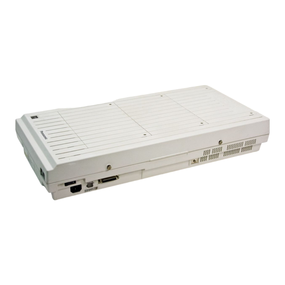
2.2 Installation of the Main Unit 2.2.2 Location of Interfaces Overview KX-TD816 External Music Jack Paging Jack System Clear Switch Reset Button Serial Interface (RS-232C) Connector Ground Terminal Battery Adaptor Connector AC Inlet Power Switch Power Indicator KX-TD1232 Ground Terminal... - Page 38 2.2 Installation of the Main Unit Inside View KX-TD816 Extension Modular Jacks Outside Line Modular Jacks Fuse Front Cover KX-TD1232 Outside Line Modular Jacks Extension Amphenol Connectors Paging Jack 2 Paging Jack 1 External Music Jack 2 External Music Jack 1...
-
Page 39: Wall Mounting
Mounting on Wooden Wall Place the template (included) on the wall to mark the screw positions. Template Template KX-TD816 KX-TD1232 Install the screws (included) into the wall. Wooden Wall... - Page 40 Mounting on Concrete or Mortar Wall Place the template (included) on the wall to mark the screw positions. Template Template KX-TD816 KX-TD1232 Drill holes and drive the anchor plugs (included) with a hammer, flush to the wall. To the wall surface...
-
Page 41: Frame Ground Connection
2.2 Installation of the Main Unit 2.2.4 Frame Ground Connection IMPORTANT Connect the frame of the main unit to ground. Loosen the screw. Insert the grounding wire. Tighten the screw. Connect the grounding wire to ground. To ground To ground General Installation... -
Page 42: Opening The
2.2 Installation of the Main Unit 2.2.5 Opening the Front Cover Loosen the two screws on the right side of the main unit. Open the front cover in the direction of arrow . screw screw screw screw Note The two screws are attached to the front cover with springs so that they will not be lost. General Installation... -
Page 43: Connection
Insert the modular plugs of the telephone line cords (4-conductor wiring) into the modular jacks on the system. Connect the line cord to the terminal board or the Central Office jack. KX-TD816 R: Ring T: Tip View of TEL Jack (Outside Line) - Page 44 2.3 Connection KX-TD1232 T2 R1 T1 R2 R: Ring T: Tip View of TEL Jack (Outside Line) (T1, R1) (T2, R2) Outside Line 07, Outside Line 08 Outside Line 05, Outside Line 06 Outside Line 03, Outside Line 04 Outside Line 01, Outside Line 02 Use 4-conductor wiring cord To Terminal Board or Modular Jacks from the Central Office.
-
Page 45: Extension Connection
2.3 Connection 2.3.2 Extension Connection KX-TD816 Extension jacks 01 through 08 are for all kinds of telephones. Maximum Cabling Distance The maximum length of the extension line cord (twisted cable) which connects the system and the extension is as follows: Diameter of the line Max. -
Page 46: Maximum Cabling Distance
2.3 Connection Connection D1: Data 1 D2: Data 2 R: Ring T: Tip Jack 08 Jack 07 View of TEL Jack (Extension) Jack 06 Jack 05 Jack 04 Jack 03 Jack 02 Jack 01 To extensions (Jacks 01 – 08) KX-TD1232 Extension jacks 1 through 16 are for all kinds of telephones. - Page 47 2.3 Connection Telephone Wiring Single Line telephone 1 pair wire (T, R) Digital proprietary telephone 1 pair wire (D1, D2) or (e.g. KX-T7536, KX-T7235) 2 pair wire (D1, D2, T, R) for eXtra Device Port Analogue proprietary telephone except KX-T7130 (e.g. KX- 2 pair wire (D1, D2, T, R) T7020, KX-T7030) KX-T7130 Analogue proprietary...
- Page 48 2.3 Connection Connection Insert the 50-pin connector to the Extension Jack as shown. Connect the wire cords to the appropriate connector pins and the terminal equipment. Refer to the Telephone Wiring (Page 45) and Pin Number Chart (Page 49). Connector type 50-pin (Amphenol 57JE series or the equivalent) To extensions...
- Page 49 2.3 Connection Pin Number Chart Pin no. EXTN. 01-08 EXTN. 09-16 8EXTN. 8EXTN. Jack Jack Jack Jack No.01 No.09 No.17 No.25 Jack Jack Jack Jack No.02 No.10 No.18 No.26 Jack Jack Jack Jack No.03 No.11 No.19 No.27 Jack Jack Jack Jack No.04 No.12...
- Page 50 2.3 Connection Pin no. EXTN. 01-08 EXTN. 09-16 8EXTN. 8EXTN. Jack Jack Jack Jack No.06 No.14 No.22 No.30 Jack Jack Jack Jack No.07 No.15 No.23 No.31 Jack Jack Jack Jack No.08 No.16 No.24 No.32 Note • "8EXTN" in the table indicates an extension expansion area for 8-Station Line Unit (KX- TD170).
- Page 51 2.3 Connection • After completing all the required inside cabling, including outside lines, extensions, external pagers and external music sources, fasten the cables with the nylon tie (included) as shown. Programming Guide References [007] Console Port and Paired Telephone Assignment [109] Expansion Unit Type Features Guide References Console...
-
Page 52: Parallelled Telephone Connection
2.3 Connection 2.3.3 Parallelled Telephone Connection Any single line telephone can be connected in parallel with a proprietary telephone as follows: Method 1: Using a Modular T-Adaptor Modular T-Adaptor (Panasonic KX-J66 or USOC RJA2X) 2-conductor wiring cord “ ” “... - Page 53 2.3 Connection Method 2: For Digital Proprietary Telephones only <Back of the KX-T7500/KX-T7400 Series DPTs> To system To single line 4-conductor wiring cord telephone “ ” “ ” Connect pins “ ” “ ” 2-conductor wiring cord “ ” “ ”...
-
Page 54: Extra Device Port (Xdp) Connection
2.3 Connection 2.3.4 EXtra Device Port (XDP) Connection A digital proprietary telephone and a single Line telephone can be connected to the same extension jack yet have different extension numbers (eXtra Device Port feature). System Programming is required for this jack. Method 1 4-conductor wiring cord Connect pins “D1”... -
Page 55: Polarity Sensitive Telephone Connection
Extensions (T, R) of jacks 17 and 18 (Extension Expansion Card 1): Outside line 09 and 10 (Note: Extensions of jacks 09 and 10 for KX-TD816, and 17 and 18 for KX-TD1232 depend on the Power Failure Transfer connection. For details, refer to Section 2.5.1 Auxiliary Connection for Power Failure Transfer.) - Page 56 2.3 Connection Reverse as shown. Extension Central Office Line Reverse here. Every time an extension telephone is replaced, repeat the above procedure. Note The KX-TD1232 is illustrated as the main unit. General Installation...
-
Page 57: External Pager (Paging Equipment) Connection
2.3 Connection 2.3.6 External Pager (Paging Equipment) Connection KX-TD816 One external pager (user-supplied) can be connected to the KX-TD816 as illustrated below. Use an RCA connector and shielded cable. • Output impedance: 600 Maximum length of the cable AWG 18 – 22: Under 10 m... - Page 58 2.3 Connection KX-TD1232 Up to two external pagers (user-supplied) can be connected to the KX-TD1232 per system as illustrated below. Use an RCA connector and shielded cable. • Output impedance: 600 Maximum length of the cable AWG 18 – 22: Under 10 m REMOTE SYSTEM INTER CONNECTION...
- Page 59 2.3 Connection Features Guide References Background Music (BGM) Paging Trunk (Outside Line) Answer From Any Station (TAFAS) General Installation...
-
Page 60: External Music Source Connection
2.3.7 External Music Source Connection KX-TD816 One music source such as a radio (user-supplied) can be connected to the KX-TD816 as illustrated below. Insert the plug to the earphone / headphone jack on the external music source. Use a two- conductor plug (3.5 mm in diameter). - Page 61 2.3 Connection KX-TD1232 Up to two music sources such as a radio (user-supplied) can be connected to the KX-TD1232 per system as illustrated below. Insert the plug to the earphone / headphone jack on the external music source. Use a two-conductor plug (3.5 mm in diameter). •...
- Page 62 2.3 Connection Features Guide References Background Music (BGM) General Installation...
-
Page 63: Printer And Pc Connection
2.3 Connection 2.3.8 Printer and PC Connection A user-supplied printer or personal computer (PC) can be connected to the system. These are used to print out or refer to the Station Message Detail Recording (SMDR) call records and system programming data. Connect the printer cable or the PC cable to the Serial Interface (RS-232C) connector. - Page 64 2.3 Connection Connection Chart for Printer / IBM Personal Computer If you connect a printer or a PC with a 25-pin cable, follow the chart below. System 25-pin Cable Printer/PC Circuit Circuit Signal Signal Type Type Name Name (EIA) (EIA) SD (TXD) RD (RXD) RD (RXD)
-
Page 65: Serial Interface (Rs-232C) Signals
2.3 Connection Serial Interface (RS-232C) Signals Frame Ground: FG Connects to the unit frame and the earth ground conductor of the AC power cord. Transmitted Data: SD (TXD): (output) Conveys signals from the unit to the printer. A "Mark" condition is held unless data or BREAK signals are being transmitted. -
Page 66: Installation Of Lightning Protectors
2.3 Connection 2.3.9 Installation of Lightning Protectors Overview A lightning protector is a device to be installed on an outside line to prevent a dangerous surge from entering the building and damaging equipment. A dangerous surge can occur if a telephone line comes in contact with a power line. Trouble due to lightning surges has been showing a steady increase with the development of electronic equipment. - Page 67 2.3 Connection Outside Installation Diagram If you install an extension outside of the main building, the following precautions are recommended: Install the extension wire underground. Use a conduit to protect the wire. (Main Building) Protectors (Another Building) Ter- Main EXTN minal Unit Board...
- Page 68 2.3 Connection Earth Rod Installation Diagram Lightning Protector (Main Building) Grounding Wire Main Unit (Underground) Earth Rod Installation location of the earth rod: Near the protector Check obstructions: None Composition of the earth rod: Metal Depth of the earth rod: More than 50 cm Size of the grounding wire: Thickness is more than 16 AWG Note •...
-
Page 69: Installation Of Optional Cards And Unit
To protect the printed circuit boards (P-boards) from static electricity, do not touch parts on the P-boards in the main unit and on the optional cards. Expansion Units KX-TD816 The following expansion units can be installed to any of the two expansion areas. One extension line unit... - Page 70 2.4 Installation of Optional Cards and Unit Note • System Programming is required for expansion unit location. <SYS PRG [109]> Default: Area 1 = 4-CO Line Unit, Area 2 = 8-Station Line Unit. • It is also possible to attach the line expansion unit to the DISA or Remote Unit and install them to the main unit.
- Page 71 Install Doorphone Card, KX-TD160. This card connects two doorphones and two door openers. Front Cover is open. Pay Tone Card for KX-TD816 Install Pay Tone Card, KX-TD189. This card supports the Pay Tone service of the central office. Under this board...
- Page 72 2.4 Installation of Optional Cards and Unit Remote Card, System Inter Connection Card, DISA Card, Doorphone Card for KX- TD1232 Install Remote Card, KX-TD196, or Remote Card High Speed Remote Card, KX-TD197. Connector This card provides data communications between the system and a remote location. System Inter Install System Inter Connection Card, Connection...
-
Page 73: Slt Message Waiting Lamp Adaptor Unit
2.4 Installation of Optional Cards and Unit SLT Message Waiting Lamp Adaptor Unit One SLT Message Waiting Lamp Adaptor Unit (KX-TD194) for KX-TD816, and up to three SLT Message Waiting Lamp Adaptor Units for KX-TD1232 can be installed. This card supports the Message Waiting feature for a single line telephone with a message waiting lamp. -
Page 74: 4-Co Line Unit Connection
2.4 Installation of Optional Cards and Unit 2.4.2 4-CO Line Unit Connection To add four outside lines (outside lines 05 through 08 for KX-TD816, and outside lines 09 through 12 for KX-TD1232), use the optional 4-CO Line Unit (KX-TD180). This unit can be installed to any of the expansion unit areas provided on the front of the main unit. -
Page 75: 8-Station Line Unit Connection
2.4 Installation of Optional Cards and Unit 2.4.3 8-Station Line Unit Connection To add eight extensions (jack numbers 09 through 16 for KX-TD816, and jack numbers 17 through 24 or 25 through 32 for KX-TD1232), use the optional 8-Station Line Unit (KX- TD170). -
Page 76: Slt Line Circuit Unit
2.4 Installation of Optional Cards and Unit 2.4.4 16 SLT Line Circuit Unit To add eight extensions which contain two single line telephones, use the optional 16 SLT Line Circuit Unit (KX-TD174). The unit can support 16 single line telephones per unit. Each single line telephone in the same jack has different extension number so that it can act as completely different extension like an eXtra Device Port feature. -
Page 77: Installing Expansion Unit
2.4 Installation of Optional Cards and Unit 2.4.5 Installing Expansion Unit The following procedures can be used to install the optional expansion units. The following steps 1 through 5 and 7 through 10 are the same for all expansion units. Step 6 is different for each unit. - Page 78 2.4 Installation of Optional Cards and Unit Hook the cabinet on the main unit and slide the cabinet to the left until it is secured. Loosen the outside screw and slide the cover to the right. Outside screw Secure the inside screw (included) to fix the cabinet to the main unit. Inside screw Note Be sure to fix the inside screw to the main unit, or the unit may not work properly.
-
Page 79: Auxiliary Connection For Power Failure Transfer
2.4 Installation of Optional Cards and Unit (If a option is to be installed) If a KX-TD180 is to be installed; Insert the modular plugs of the telephone line cords (4-conductor wiring) into the modular jacks on the unit. (T1/R1) (T2/R2) TD816: Outside Line 05, Outside Line 06 TD1232: Outside Line 09, Outside Line 10... - Page 80 2.4 Installation of Optional Cards and Unit Note • For details about the jack for Power Failure Transfer, refer to Section 2.5.1 Auxiliary Connection for Power Failure Transfer. • For cable pin numbers to be connected, see "Pin Number Chart" in Section 2.3.2 Extension Connection and "Pin Number Chart for the KX-TD174"...
- Page 81 2.4 Installation of Optional Cards and Unit Note If two expansion units are installed, cut the cabinet cover(s) on the lower cabinet(s) to allow the cords from upper cabinet to go down through the cabinet cover(s). To protect the cords, smooth the cut edges.
- Page 82 2.4 Installation of Optional Cards and Unit Note When installing a connector like the type shown below, unscrew the lower hook-pin also. Then drive both accessory screws. Accessory screw Amphenol 57JE type 50-pin Accessory connector screw To attach the Amphenol 57JE type (Plug) to the connector, drive the accessory screw into the upper part.
- Page 83 2.4 Installation of Optional Cards and Unit Pin Number Chart for the KX-TD174 Clip For KX-TD1232 For KX-TD1232 For KX-TD816 CONN Terminal (Expansion 1) (Expansion 2) (KX-A205) Jack No.9-16 Jack No.17-24 Jack No.25-32 Jack. 09-1 Jack. 17-1 Jack. 25-1 Jack. 10-1 Jack.
-
Page 84: Pay Tone Card Installation
Attach the Pay Tone Card(s) (KX-TD189) to the CO Line Card, with the spacers (Accessary included). One Pay Tone Card for KX-TD816, and up to two Pay Tone Cards for KX-TD1232 can be installed to the initial CO Line Card. - Page 85 After installing the Pay Tone Card, if you hear a noise of the pay-tone signal, cut the option Jumper Wires, OPJPA through OPJPH, in the CO Card. KX-TD816: OPJPA through OPJPD corresponds to outside line (CO) 01 through 04 respectively.
- Page 86 2.4 Installation of Optional Cards and Unit Installing to the Optional 4-CO Line Unit The following procedures must be done before installing the 4-CO Line Unit (KX-TD180) to the main unit. Loosen five screws located on the rear of the 4-CO Line Unit. Remove the back plate and take out the P-board.
-
Page 87: Disa Card / Unit And Remote Card / Unit Installation
The DISA Card (KX-TD191 and KX-TD199), DISA Unit (KX-TD190), Remote Card (KX- TD196), High Speed Remote Card (KX-TD197) and Remote Unit (KX-TD198) can be installed as follows. Main Unit For DISA feature For remote access KX-TD816 KX-TD190, KX-TD198, KX-TD198 with KX-TD199 KX-TD190 with KX-TD197 KX-TD1232... - Page 88 2.4 Installation of Optional Cards and Unit Hook the cabinet onto the main unit and slide the cabinet to the left until it is secured. D816 DIGITAL SUPER HYBRID SYSTEM Installing the DISA Card (KX-TD199) to the Remote Unit (KX-TD198) / Installing the High Speed Remote Card (KX-TD197) to the DISA Unit (KX-TD190) It is possible to install the required card in the unit before installing the unit to the main unit.
- Page 89 2.4 Installation of Optional Cards and Unit Install the card, secure the screw (included with the unit) and connect the cable to the connector. DISA Card Remote Card Flatten the cable to replace the inside cover properly. Cable Side View Replace the inside cover and secure the four screws on the back.
- Page 90 2.4 Installation of Optional Cards and Unit Attaching another line expansion unit to the DISA Unit (KX-TD190) or Remote Unit (KX- TD198) and install them to the system Remove the front cover of the DISA or Remote Unit. The KX-TD198 users must set the MODE switch to 2. MODE Attach the expansion unit to the DISA or Remote Unit as shown below.
- Page 91 2.4 Installation of Optional Cards and Unit Hook the cabinets onto the main unit and slide the cabinets to the left until they are secured. D816 DIGITAL SUPER HYBRID SYSTEM Loosen the outside screw of the expansion unit and slide the cover to the right. D816 DIGITAL SUPER HYBRID SYSTEM Outside screw...
- Page 92 2.4 Installation of Optional Cards and Unit Fix the cords to the wall as shown here, so that the front cover can be opened. D816 DIGITAL SUPER HYBRID SYSTEM Cord holder KX-TD1232 Installing the DISA Card (KX-TD191) Insert the upper side of the DISA Card into the two hooks on the main unit. DISA Card Press down the two corners of the lower side of the DISA Card.
- Page 93 2.4 Installation of Optional Cards and Unit Installing the Remote Card (KX-TD196) or High Speed Remote Card (KX-TD197) Insert the upper side of the Remote Card into the two hooks on the main unit. Remote Card Press down the two corners of the lower side of the Remote Card. Connect the cord to the Remote Card Connector.
-
Page 94: Doorphone And Door Opener Connection
2.4 Installation of Optional Cards and Unit 2.4.8 Doorphone and Door Opener Connection To connect up to two doorphones (KX-T30865) and up to two door openers (user-supplied), a Doorphone Card (KX-TD160) is required. Installing the Doorphone Loosen the screw to separate the doorphone into two halves. screw Install the base cover to the wall with two screws. - Page 95 Connect a 4-conductor modular connector to the Doorphone Card Cabinet, and pass the cord through the groove in the cabinet. Attach the Doorphone Card Cabinet to the main unit and press down. Connect the cord to the Doorphone Card Connector. KX-TD1232 KX-TD816 To Terminal Box General Installation...
- Page 96 2.4 Installation of Optional Cards and Unit Wiring of the Doorphone Connect the Doorphone Card to the terminal box using a 4-conductor modular connector. Connect the wires of doorphone 1 to the red and green screws of the terminal box. Connect the wires of doorphone 2 to the yellow and black screws of the terminal box.
- Page 97 2.4 Installation of Optional Cards and Unit Loosen the screws on the terminal strip. Insert the wires coming from the door openers into holes and tighten the screws. To door opener 2 To door opener 1 Note • The KX-TD1232 is illustrated as the main unit. •...
- Page 98 2.4 Installation of Optional Cards and Unit Maximum cabling distance of the doorphone and the door opener line The maximum length of the doorphone and door opener line that connects to the main unit is shown below: 26 AWG: Under 70 m 24 AWG: Under 113 m 22 AWG: Under 180 m Doorphone...
-
Page 99: Slt Message Waiting Lamp Adaptor Unit Connection
2.4 Installation of Optional Cards and Unit 2.4.9 SLT Message Waiting Lamp Adaptor Unit Connection Name and Locations Side View Connector ( TO SYSTEM ) Connector ( TO EXTN ) Power light AC inlet Binders Ground terminal DC input/output connector Specifications 1. - Page 100 2.4 Installation of Optional Cards and Unit 2. Characteristics DC Power Supply to Stations 85 V, 1.2 mA (max) Primary Power 230 VAC, 50 Hz, 0.8 A (max) Environmental Requirements 0 °C – 40 °C, 10 % – 90 % rel. hum. This is the maximum current when three TD194s are connected by DC input/output interfaces (only the main TD194 is connected to an AC outlet).
- Page 101 2.4 Installation of Optional Cards and Unit Opening the Front Cover Loosen the screw. Slide the cover while pressing the mark. Screw Note The screw cannot be removed from the unit. Frame Ground Connection IMPORTANT Connect the system frame to the ground. Loosen the screw.
- Page 102 Insert the two 50-pin connectors to the jacks as shown below. The connector "TO SYSTEM" should be connected to the cable which is connected to the KX-TD816/KX-TD1232. Also, the connector "TO EXTN" should be connected to the cable which is connected to the extensions.
-
Page 103: Pin Number Chart
2.4 Installation of Optional Cards and Unit If two units are connected with the DC IN/OUT or a Battery Adaptor (KX-A46) is connected to the unit, insert the 4-pin connectors to the jacks as shown below. Also connect the ground terminal of the unit to the minus (-) terminal of a car battery using an earth wire. - Page 104 2.4 Installation of Optional Cards and Unit CONN. To System To Extension Connector Connector (CN1) (CN2) EXTN. 05 EXTN. 06 EXTN. 06 EXTN. 07 EXTN. 07 EXTN. 08 EXTN. 08 EXTN. 09 EXTN. 09 EXTN. 10 EXTN. 10 EXTN. 11 EXTN.
-
Page 105: Closing The Front Cover
2.4 Installation of Optional Cards and Unit Closing the Front Cover Fasten the binders. Replace the cover and tighten the screw. screw Tie together all of the connected cords and attach them to the wall so that the cords cannot be pulled out of the system. - Page 106 2.4 Installation of Optional Cards and Unit Starting the unit Plug the AC cord into the system AC inlet and an AC outlet. Avoid sharing the AC outlet of this system with other office equipment. Use a dedicated AC outlet only. AC Outlet 134 cm CAUTION...
-
Page 107: System Connection
2.4 Installation of Optional Cards and Unit 2.4.10 System Connection To connect two main units, use two optional System Inter Connection Cards (KX-TD192) and the Connection Cable (included in the cards). Insert the upper side of the System Inter Connection Card into two hooks on the main unit (Master System). - Page 108 2.4 Installation of Optional Cards and Unit Close the latches on both systems. Connection Cable Open the ROM Cover in the Slave System and set the Master/Slave Switch on the CPU Card to "Slave" position. Turn the power on. Note •...
-
Page 109: Battery Adaptor Connection
2.4 Installation of Optional Cards and Unit 2.4.11 Battery Adaptor Connection User-supplied car batteries can be used as a backup power supply in the event of a power failure. In case of a power failure, the batteries automatically maintain power to the main unit. The optional Battery Adaptor (KX-A46) is required. - Page 110 Insert the plug of the battery adaptor into the battery adaptor connector on the main unit. Connect the ground wire to the ground terminal on the main unit. Ground Terminal Ground Wire To ground KX-TD816 Plug Power Switch Ground Terminal Ground Wire...
- Page 111 2.4 Installation of Optional Cards and Unit Hook the battery adaptor onto the screw heads. Metal Plates Front Screws (big) Wall Screws Bottom (small) Rear Mounting on Concrete or Mortar Walls; At step 4, drill two holes and drive the anchor plugs with a hammer, flush to the wall, and install the big screws into the anchor plugs.
-
Page 112: Auxiliary Connection For Power Failure Transfer
Insert the modular plugs of connection cords (4-conductor wiring) to the modular jacks of 4- CO Line Unit and Extension Line Unit 1. (In the case of KX-TD816, one Extension Line Unit is available.) T2 R1 T1 R2 R: Ring... - Page 113 2.5 Auxiliary Connection for Power Failure Transfer Note • In the event of a power failure, system memory is protected by a factory-provided lithium battery. There is no memory loss except the memories of Camp-on, Saved Number Redial, Last Number Redial, Call Park and Message Waiting. •...
-
Page 114: Closing The
2.6 Closing the Front Cover 2.6 Closing the Front Cover 2.6.1 Closing the Front Cover Fasten all the cables and cords with the cord fastener. Replace the cover and tighten the screw. Note Be sure to tighten two screws, or the unit may not work properly. screw screw screw... - Page 115 2.6 Closing the Front Cover Tie together all of the connected cords and attach them to the wall so that the cords cannot be pulled out of the main unit. General Installation...
-
Page 116: Starting The System For The First Time
Slide the System Clear Switch to the "NORMAL" position while the power indicator is flashing (within approximately 10 seconds). The system will be initialised with default values. The system will also check the outside lines, extensions, and optional cards and units. KX-TD816 Reset Button SYSTEM CLEAR System Clear Switch... - Page 117 2.7 Starting the System for the First Time KX-TD1232 System Clear Switch SYSTEM CLEAR CLEAR NORMAL RESET Reset Button To AC Outlet Power Power Indicator Switch Notice • After pressing the Reset Button, slide the System Clear Switch to the "NORMAL" position at step 6 while the power indicator is flashing (within approximately 10 seconds).
-
Page 118: System Restart
2.8 System Restart 2.8 System Restart 2.8.1 System Restart After starting the system, if the system does not operate properly, restart the system. Before restarting the system, try the system feature again to confirm whether there definitely is a problem or not. System Restart causes the following: Camp-on is cleared. -
Page 119: System Data Clear
2.9 System Data Clear 2.9 System Data Clear 2.9.1 System Data Clear After storing or changing the system programming data, it is possible to clear your programming data stored in the system, if required. The system will restart with the default setting. - Page 120 2.9 System Data Clear General Installation...
-
Page 121: Isdn Installation
Section 3 ISDN Installation ISDN Installation... -
Page 122: Isdn Network Outline
3.1 ISDN Network Outline 3.1 ISDN Network Outline 3.1.1 Overview To use the ISDN Line Service, the following unit can be installed to the KX-TD816 and KX- TD1232. 2-ISDN S0 Line Unit (KX-TD280) This unit adds two Basic Rate Interface (BRI) ISDN S0 lines. One KX-TD280 can be connected to the KX-TD816 and KX-TD1232. -
Page 123: Isdn Line Connection
P-boards in the main unit and on the optional units. The ISDN line unit should not be installed only to the Slave system. KX-TD816 One ISDN Line Unit (KX-TD280 or KX-TD286) can be installed to any expansion area. - Page 124 3.2 ISDN Line Connection KX-TD1232 One ISDN Line Unit (KX-TD280 or KX-TD286) and/or one PRI ISDN Line Unit (KX- TD290) can be installed to any expansion area. The KX-TD290 can be installed with the KX-TD280 or KX-TD286, but not with the analogue outside line unit.
-
Page 125: Installing The Unit
3.2 ISDN Line Connection 3.2.2 Installing the Unit Step 6 is different for each unit. The ISDN unit should not be installed only to the Slave system. The KX-TD1232 is illustrated as the main unit. Loosen two screws on the cover plate. Insert fingers into the slits to remove the cover plate. Slit Slit Note... - Page 126 3.2 ISDN Line Connection Hook the cabinet to the main unit and slide the cabinet to the left until it is secured. Loosen the outside screw and slide the cover to the right. Outside screw Secure the inside screw (included) to fix the cabinet to the main unit. Inside screw Note Be sure to fix the inside screw to the main unit, or the unit may not work properly.
- Page 127 All ports of the KX-TD280 and KX-TD286 can also be used for internal ISDN lines. For the KX-TD816, jack numbers S05 and S06 of the KX-TD286 are fixed as internal ISDN lines. To connect internal ISDN lines, refer to Section 3.2.3 Internal ISDN S0 Line Connection.
- Page 128 3.2 ISDN Line Connection If a KX-TD290 is to be installed (KX-TD1232 only): Prepare the required plugs. Two 4-pin plugs are included with the KX-TD290. From Network To the unit From Network To the unit Insert the plug into a jack on the unit. Connect a grounding wire to the ground terminal on the extension expansion unit.
- Page 129 3.2 ISDN Line Connection Cover the cords with the cord holder (included). Cord holder Fix the cords to the wall as shown so that the front cover can be opened. Note If two or three expansion units are installed, cut the cabinet covers on the lower cabinets to allow the cords from the upper cabinet to go down through the cabinet covers.
-
Page 130: Internal Isdn S0 Line Connection
3.2 ISDN Line Connection 3.2.3 Internal ISDN S0 Line Connection The ISDN S0 Bus on the 2-ISDN S0 Line Unit (KX-TD280) and the 6-ISDN S0 Line Unit (KX-TD286) can be used as internal S0 bus. Each port can be used as either external or internal ISDN S0 Lines. - Page 131 3.2 ISDN Line Connection Press the Reset Button with a pointed tool on the main unit. Note For installing the KX-TD280 or KX-TD286 to main unit, refer to the Section 3.2.2 Installing the Unit respectably. Features Guide References Integrated Services Digital Network (ISDN) Extension Maximum cabling distance of S0 bus connection The maximum length of the extension line cord that connects the main unit and the ISDN Terminal Equipment (TE) is shown below.
- Page 132 3.2 ISDN Line Connection Wiring with Terminating Resistors (TR) The ISDN S0 bus should be terminated with two100 terminating resistors (TR). Main † Unit † TE 1 TE 8 TR 100 TR 100 Power Supply for ISDN Terminal Equipment (TE) The system does not provide a power supply to terminal equipment (TE).
-
Page 133: E & M Installation
Section 4 E & M Installation E & M Installation... -
Page 134: E & M (Tie) Line Service Outline
To use the E & M (TIE) Line Service, the following unit is required. E & M (TIE) Line Unit (KX-TD184) The unit supports up to four ports for E & M (TIE) Line Service. One KX-TD184 can be connected to the KX-TD816 and KX-TD1232. E & M Installation... -
Page 135: Specifications
4.1 E & M (TIE) Line Service Outline 4.1.2 Specifications Item Description E&M (TIE) Line Types Type 5 only Transmission 2-wire or 4-wire voice path (Programmable) (Note) Maximum cabling distance of the E&M line cord (twisted cable): 22 AWG: Under 9.6 km Transmission levels 2-wire voice path: -3 db (transmit/receive) -
Page 136: E & M (Tie) Line Installation
P-boards in the main unit and on the optional unit. KX-TD816 One E & M (TIE) Line Unit (KX-TD184) can be installed to either of the two expansion areas on the KX-TD816. Expansion area 2 Expansion 4 E&M... - Page 137 4.2 E & M (TIE) Line Installation KX-TD1232 One E & M (TIE) Line Unit (KX-TD184) can be installed to any expansion area on the KX- TD1232. Expansion area 3 Expansion area 2 4 E&M Expansion area 1 D1232 Expansion Unit Connectors Remove the front cover plate(s).
-
Page 138: Installing The Unit
4.2.2 Installing the Unit Installing one unit to the system allows four E&M (TIE) lines to be connected to outside lines 05 through 08 for the KX-TD816, or outside lines 09 through 12 or 21 through 24 for the KX- TD1232. - Page 139 4.2 E & M (TIE) Line Installation Hook the cabinet to the main unit and slide the cabinet to the left until it is secured. Loosen the outside screw and slide the cover to the right. Outside screw Secure the inside screw (included) to fix the cabinet to the main unit. Inside screw Note Be sure to fix the inside screw to the main unit, or the unit may not work properly.
- Page 140 4.2 E & M (TIE) Line Installation Insert the Amphenol Connector into the jack. Connector type 50-pin (Amphenol 57JE series or the equivalent) To terminal Board from the E&M (TIE) Line. Note • To fix the connector, refer to Section 2.4.5 Installing Expansion Unit, Amphenol 57JE Type (screw-attach-type 50-pin connector) Connection for KX-TD170.
- Page 141 4.2 E & M (TIE) Line Installation Fix the cords to the wall as shown so that the front cover can be opened. Note If two or three expansion units are installed, cut the cabinet covers on the lower cabinets to allow the cords from the upper cabinet to go down through the cabinet covers.
-
Page 142: E&M (Tie) Line Connection
4.2 E & M (TIE) Line Installation 4.2.3 E&M (TIE) Line Connection Pin Number Chart (E&M Line) Connect Number Cable Color Clip No. E&M Line of Dots ORN-RED 2-wire or 4-wire - send ORN-BLK YEL-RED 4-wire - receive YEL-BLK GRY-RED E Lead NO.1 GRY-BLK... - Page 143 Cable Pins to be Connected (E&M Line) • E&M Line Wiring 50-pin Connector Block Terminal E&M Line 1 Bridging Clips Connecting to another KX-TD816/KX-TD1232 system (KX-TD184) 2-wire voice path KX-TD184 Another KX-TD184 4-wire voice path KX-TD184 Another KX-TD184 E & M Installation...
- Page 144 4.2 E & M (TIE) Line Installation Connecting to the E&M Central Office 2-wire voice path KX-TD184 E&M Central Office -48V -48V GROUND GROUND 4-wire voice path KX-TD184 Another KX-TD184 Voice Voice Transmit Receive Voice Voice Receive Transmit -48 V -48 V GROUND GROUND...
- Page 145 4.2 E & M (TIE) Line Installation E&M Sequences You can choose one of the following E&M sequences. <SYS PRG [129]> Continuous E&M Seize Dial Answer Disconnect E-Wire Wink M-Wire If you select Immediate , this signal will not appear. Pulsed E&M with Answer signal Seize Dial...
- Page 146 4.2 E & M (TIE) Line Installation E & M Installation...
-
Page 147: Dect Installation
Section 5 DECT Installation DECT Installation... -
Page 148: Wireless System Outline
PS: DECT Portable Station (KX-TD7500) Up to 16 PSs in the KX-TD816 system and up to 64 PSs in the KX-TD1232 system can be used as extensions. For more details about the PS, please refer to the User Manual. -
Page 149: Rf Specifications
5.1 Wireless System Outline 5.1.2 RF Specifications Item Description Radio Access Method Multi Carrier TDMA-TDD Multiplex Carrier Frequency Interval 1728 kHz Transmission Speed 1152 kbps Frame Structure 10 ms / frame (T 12 slots + R 12 slots) Modulation Scheme GFSK Roll-off factor = 0.5 50% roll-off in the transmitter... -
Page 150: Procedure Flow Chart
5.1 Wireless System Outline 5.1.3 Procedure Flow Chart Consider the service area required for the Refer to Section 5.2.1 Site Planning. users by referring to Site Planning. Connect a Cell Station Interface Unit Refer to Section 5.2.2 Location of the Unit and to the main unit. -
Page 151: Wireless System Installation
5.2 Wireless System Installation 5.2 Wireless System Installation 5.2.1 Site Planning Choosing the best site for the Cell Station (KX-TD142) requires careful planning and testing of essential areas. The best location may not always be convenient for installation. Please read the following information before you install the unit. - Page 152 5.2 Wireless System Installation • The table below shows the transmission tendency of radio waves when they reach objects made from various materials. Object Material Transmission Tendency Wall Concrete The thicker they are, the less radio waves penetrate them. Ferroconcrete Radio waves can penetrate them, but the more iron there is, the more radio waves are reflected.
- Page 153 5.2 Wireless System Installation <Basic location> <Location example for a building which has an object in the centre.> Object Cell Stations 5 – 10 m Precautions • The Cell Station should be kept free of dust, moisture, high temperature (more than 40 °C), low temperature (less than 5 °C), vibration, and should not be exposed to direct sunlight.
-
Page 154: Location Of The Unit
5.2 Wireless System Installation 5.2.2 Location of the Unit KX-TD816 with the KX-TD144 One Cell Station Interface Unit (KX-TD144) can be connected to either of the two expansion areas. Up to two Cell Stations (KX-TD142) can be connected to the KX-TD144. - Page 155 5.2 Wireless System Installation KX-TD1232 with the KX-TD144 Up to two Cell Station Interface Units (KX-TD144) can be connected to any of the three expansion areas. Up to two Cell Stations (KX-TD142) can be connected to the KX-TD144. Expansion KX-TD144 area 3 KX-TD142 Expansion...
- Page 156 5.2 Wireless System Installation KX-TD816 with the KX-TD146 One Cell Station Interface Unit (KX-TD146) can be connected to either of the two expansion areas. Up to six Cell Stations (KX-TD142) can be connected to the KX-TD146. KX-TD146 Expansion area 2...
- Page 157 5.2 Wireless System Installation KX-TD1232 with the KX-TD146 Up to two Cell Station Interface Units (KX-TD146) can be connected to any of the three expansion areas. Up to six Cell Stations (KX-TD142) can be connected to the KX-TD146. Expansion KX-TD146 area 3 KX-TD142 Expansion...
-
Page 158: Installing The Unit
5.2 Wireless System Installation 5.2.3 Installing the Unit The following procedures can be used to connect Cell Station Interface Unit to the main unit, and then the Cell Station to the Cell Station Interface Unit. The KX-TD1232 is illustrated as the main unit. Loosen the two screws on the cover plate. - Page 159 5.2 Wireless System Installation Hook the cabinet on the main unit and slide the cabinet to the left until it is secured. Loosen the outside screw and slide the cover to the right. Outside screw Secure the inside screw firmly to fix the cabinet to the main unit. Inside screw Note Be sure to fix the inside screw to the main unit, or the unit may not work properly.
- Page 160 5.2 Wireless System Installation Wireless Extension Connection Use a Cell Station Cord (4-conductor wiring - included) and 4-pin plug (included) to connect the cell station line. There are 2 plugs for the KX-TD144 and 6 plugs for the KX- TD146 to connect the Cell Stations. Maximum length of the cable: AWG 24 (0.6 mm in diameter): Under 1 km Insert the wires of the 4-conductor wiring cord into the holes in the plug to connect pins "D1", "D2", "V1"...
- Page 161 5.2 Wireless System Installation Insert the modular plug into the Cell Station, and attach the ferrite core (included) to the plug cord. Ferrite Core Roll the cord once around the ferrite core 15 cm and close the core. Survey the site for the Cell Station by testing the radio signal. Refer to the Section 5.2.5 Site Survey.
- Page 162 4-pin plug Note Do not peel off the wire coating. Insert the wires all the way. Insert the plug into a jack on the unit. <KX-TD816> <KX-TD1232> Jack Jack Connect the ground terminal to ground. Note: If other expansion units are...
- Page 163 5.2 Wireless System Installation Cover the cords with the cord holder (included). Cord holder Fix the cords to the wall as shown so that the front cover can be opened. Note If two expansion units are installed, cut the cabinet cover(s) on the lower cabinet(s) to allow the cords from the upper cabinet to go down through the cabinet cover(s).
- Page 164 5.2 Wireless System Installation Programming Guide References [650] PS Registration [653] PS Extension Name Set [671] PS Extension Number Set [672] PS Password Set [680] Cell Station Number Assignment for Master CS Features Guide References Digital Wireless Connection DECT Installation...
-
Page 165: Selecting The Display Language
5.2 Wireless System Installation 5.2.4 Selecting the Display Language The default setting of the PS displaying language is "AUTO (English)". If Spanish display is required, follow the procedure below. Press (Function). Display: KEY Press (Book) 2 times. • You can also search by pressing (Next) or (Previous). -
Page 166: Site Survey
5.2 Wireless System Installation 5.2.5 Site Survey Site Survey Specification The KX-TD7500 portable station has Radio Signal Test Mode which monitors the state of link as one of the means to determine the site planning for the KX-TD142. In the mode, the frame loss and signal strength of a synchronous slot, and the signal strength of the other slots can be measured when the portable station is linking with the KX-TD142. - Page 167 Use a personal computer to check the Cell Station (CS) ID number. File: E1232B2.EXE Main Menu Display Main Menu Off-line Empty Panasonic Digital Super Hybrid System (DECT) Operating & Maintenance Tool Ver4.XXB2 (C) COPYRIGHT 1997 KYUSHU MATSUSHITA ELECTRIC CO.,LTD. 1.System Data Programming (BATCH) 2.System Data Programming (INTERACTIVE) 3.Disk File Management...
- Page 168 EXPII: KX-TD146 (Cell Station Interface Unit) Note • The KX-TD144 / KX-TD146 can only be installed to the Master System. • One EXP for the KX-TD816 and a maximum of two EXPs for the KX-TD1232 can be installed per system. DECT Installation...
- Page 169 5.2 Wireless System Installation Assigning the Cell Station ID Number to the PS Set the PS Power Switch to ON while pressing (Talk), (Recell) and at the same time. Display: FUNCTION<0-4> Press Display example: CS NO?(1-8) Enter the Cell Station number. Display example: CS ID1= Press (Talk).
- Page 170 5.2 Wireless System Installation Unplugging the Cable from the Cell Station After assigning the Cell Station ID number to the PS, unplug the cable from the Cell Station once. DIP-Switch Setting After unplugging the Cell Station once, set the DIP-Switch as follows. Switch the Radio Signal Test Switch from OFF to ON.
- Page 171 5.2 Wireless System Installation Note • To see the signal strength of more than one Cell Station, the channel for each Cell Station needs to be set. • Up to eight Cell Stations can be surveyed at the same time. If more than one Cell Station is in Radio Signal Test mode, each DIP-Switch channel must be different.
- Page 172 5.2 Wireless System Installation Display example: When synchronised When not synchronised CH0 SLOT:06 SYNC CH0 SLOT:06 Abbreviation of L:12 0000/0100 L:12 SYNCHRONOUS Channel number Frame counter (0000 – 9999) (0 – 9) Frame error (0000 – 9999) Slot number (00 – 23) Signal strength level (00 –...
- Page 173 5.2 Wireless System Installation Press (Talk). • The result is recorded. Display example: LOG NO.?(0-9) 0 STORED Note • The results of measurement for the 24 slots on the channel are saved each time a channel is set. If the same channel is set, the new results override the previous ones. Therefore, a measurement of 10 channels 24 slots in total can be made.
- Page 174 5.2 Wireless System Installation After the Site Survey After obtaining the proper measurement results, the following procedures are required before mounting the Cell Station to the wall. Disconnect the AC adaptor. Switch the Radio Signal Test Switch of the Cell Station from ON to OFF. Radio Signal Test Switch Connect the cable from the Cell Station Interface Unit the Cell Station, and pass the cord through the groove on the unit.
-
Page 175: Wall Mounting
5.2 Wireless System Installation 5.2.6 Wall Mounting Place the template (included) on the wall to mark the two screw positions. Install the two screws (included) into the wall. Hook the Cell Station on the screw heads. Mounting on Concrete or Mortar Walls In step 2, drill two holes and drive the anchor plugs (included) with a hammer flush to the wall. - Page 176 5.2 Wireless System Installation DECT Installation...
- Page 177 Section 6 Troubleshooting Troubleshooting...
-
Page 178: Troubleshooting
6.1 Troubleshooting 6.1 Troubleshooting 6.1.1 Installation PROBLEM PROBABLE CAUSE POSSIBLE SOLUTION Extension does not operate. Bad printed circuit board Exchange printed circuit board for (Extension Card). another printed circuit board. Bad connection between the Take the extension and plug it into the system and extension. -
Page 179: Connection
The T/R is connected to the D1/D2. Use the correct cord (inner 2 an extension? wires are for T/R and the outer 2 wires are for D1/D2). KX-TD816/ extension KX-TD1232 *The P1/P2 is connected to the D1/D2. Use the correct cord (2... - Page 180 Reconnect the outside lines previous.) to the T1/R1 or T2/R2 of the telephone jack using 2- conductor wiring. Can you dial out on an Outside line KX-TD816/ outside line? KX-TD1232 Outside lines are connected to the T2/R1. Outside line KX-TD816/ KX-TD1232 Troubleshooting...
-
Page 181: Operation
6.1 Troubleshooting 6.1.3 Operation PROBLEM PROBABLE CAUSE POSSIBLE SOLUTION • When using the • The HANDSET / • When the headset is not used, set the speakerphone mode with a HEADSET selector is set to HANDSET / HEADSET selector to analogue proprietary the "HEADSET"... -
Page 182: Using The Reset Button
6.1 Troubleshooting 6.1.4 Using the Reset Button If the system does not operate properly, use the Reset Button. (If Master and Slave Systems are in operation by System Connection for KX-TD1232, reset both systems.) Before using the Reset Button, try the system feature again to confirm whether there definitely is a problem or not. - Page 183 6.1 Troubleshooting KX-TD816 Extension (T, R) of jack number 01: Outside line 01 Extension (T, R) of jack number 02: Outside line 02 Extension (T, R) of jack number 09: Outside line 05 Extension (T, R) of jack number 10: Outside line 06...
- Page 184 Index...
-
Page 185: Index
Index Section 7 Index... - Page 186 Index Numerics 16 SLT Line Circuit Unit (KX-TD174) E & M (TIE) Line Connection 2-ISDN S0 Line Unit (KX-TD280) 22, 122, 123, E & M (TIE) Line Service 15, 134 124, 127, 130 E & M (TIE) Line Unit (KX-TD184) 22, 134, 4-CO Line Unit (KX-TD180) 22, 69, 70, 74, 86...
- Page 187 Index KX-TD191 (DISA Card) 23, 72, 87, 92 Connection KX-TD192 (System Inter Connection Card) Specifications 99, 135, 149 72, 107 Starting the System for the First Time KX-TD194 (SLT Message Waiting Lamp Adaptor System Capacity 14, 30 Unit) 23, 73 System Clear Switch 116, 118, 119, 182 KX-TD196 (Remote Card)
- Page 188 Index...
- Page 189 This is a Class A product. In a domestic environment this product may cause radio interference in which case the user may be required to take adequate measures. See More Panasonic Manuals www.voicesonic.com Phone: 877-289-2829 Copyright: This manual is copyrighted by Kyushu Matsushita Electric Co., Ltd. (KME).
Need help?
Do you have a question about the KX-TD816 and is the answer not in the manual?
Questions and answers