Table of Contents
Advertisement
Quick Links
Advertisement
Table of Contents

Subscribe to Our Youtube Channel
Related Manuals for PACOM PDR16-RMT Series


Summary of Contents for PACOM PDR16-RMT Series
-
Page 3: Compliance Notice Of Fcc
Digital Video Recorder WARNING RISK OF ELECTRIC SHOCK DO NOT OPEN WARNING: TO REDUCE THE RISK OF ELECTRIC SHOCK, DO NOT REMOVE COVER (OR BACK). NO USER-SERVICEABLE PARTS INSIDE. REFER SERVICING TO QUALIFIED SERVICE PERSONNEL. The lightning flash with arrowhead symbol, within an equilateral triangle, is intended to alert the user to the presence of uninsulated "dangerous voltage"... -
Page 4: Important Safeguards
User’s Manual Important Safeguards 1. Read Instructions 10. Lightning All the safety and operating instructions should be read before the For added protection for this equipment during a lightning storm, or appliance is operated. when it is left unattended and unused for long periods of time, unplug it from the wall outlet and disconnect the antenna or cable system. -
Page 5: Table Of Contents
Digital Video Recorder Table of Contents Chapter 1 — Product Information ..................1 Features.........................1 System Types ........................1 System Diagram ......................1 Front Panel ........................2 Rear Panel........................2 Turning On the DVR ......................3 Turning Off the DVR ......................3 Chapter 2 — Tools......................5 SmartGuard ........................5 Overview ........................5 Features ........................5 Main GUI ........................5... - Page 6 User’s Manual...
-
Page 7: Chapter 1 - Product Information
Digital Video Recorder Chapter 1 — Product Information Features Compatible with color cameras and other standard video sources Compatible with network cameras (PDR32-HYB model only) Video synchronization not required Pentaplex operation for simultaneous recording, multi-screen viewing, playback, remote monitoring and archiving Versatile display formats for convenient user interface;... -
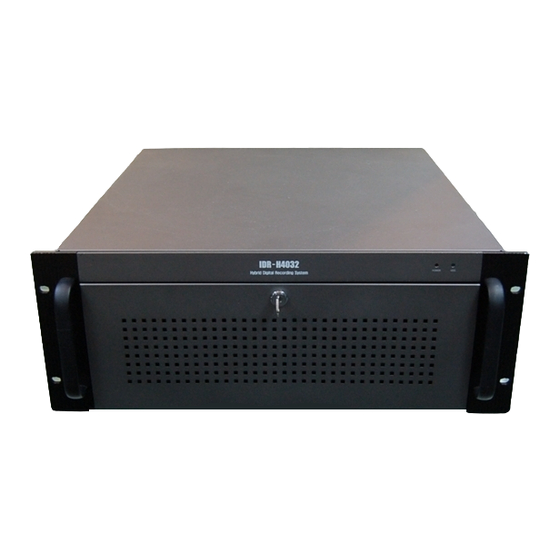
Page 8: Front Panel
Front Panel Rear Panel PDR16-RMT-RT model PDR16-RMT series and PDR32-HYB models PDR32-RMT and PDR32-RMT-X models NOTE: Windows may not operate properly when using the USB connectors on the front panel of the DVR, depending on the model type of the USB device. In this case, connect the USB device after Windows boots... -
Page 9: Turning On The Dvr
Digital Video Recorder Turning On the DVR Press the power button located on the front panel to turn the system on. The system goes into the SmartGuard mode as soon as it finishes its boot process. CAUTION: The system will lock up if the monitor does not have high enough resolution. The DVR requires 1024x768 resolution. - Page 10 User’s Manual...
-
Page 11: Chapter 2 - Tools
Digital Video Recorder Chapter 2 — Tools SmartGuard Overview SmartGuard is powerful surveillance software. It provides multiplexer functions, digital time-lapse recording and event-driven recording. SmartGuard also provides motion detection, PTZ control and various image enhancement functions. NOTE: The first time you turn on the system, it will immediately begin recording. If you have less than 32 cameras, you must enter the setup screen and deactivate any inputs to which cameras are not connected;... - Page 12 User’s Manual Quit: Click the button to quit the system. Login / Logout: Click the button to log in or log out the system. Logging In/Out the System Click the Logout button after logging out, the following User Login dialog box appears. Enter the User ID and Password and then click the OK button if you want to log in the system.
-
Page 13: Ptz Control
Digital Video Recorder HDD Indicator: Shows the remaining hard disk space. Power LED: The Power LED is lit when the DVR is On. Alarm LED: The Sensor Detect LED is lit when the sensor has been detected. Mode Status: The Recording LED is lit when the DVR is in the recording mode. HDD Usage: The Repeat Recording LED is lit when the DVR is set to repeat recording in case of recording space shortage. - Page 14 User’s Manual NOTE: Up to 128 presets can be set, depending on the specification of installed PTZ devices or dome cameras. Make sure available preset numbers first to make the PTZ preset function work properly. NOTE: If you want to set up the advanced PTZ control, place the cursor on the PTZ control panel, and click the right mouse button.
- Page 15 Digital Video Recorder Event Logging To scroll up and down the list, hold down the left mouse button on the list and move the cursor up and down, or roll the mouse wheel on the list. NOTE: Event log list displays the conditions of hard disk drives when the installed IDE hard disk drives support S.M.A.R.T.
-
Page 16: Smartguard Setup
User’s Manual Manual Alarm Output: In general, the alarm is activated automatically when any related sensor is activated. However, the user can activate all the alarm output manually by clicking the button while it is released or deactivate all the alarm output by clicking the button when it is pressed. Setup: When the Setup button is clicked, a dialog box appears. - Page 17 Digital Video Recorder 3. Click the System Info… button, and the System Info. dialog box appears. The dialog box displays the information of the installed cards, driver, software, hard disk drive, and OS on the system. 4. Click the Event log button to display the event log list of the system. 5.
- Page 18 User’s Manual 14. Move to Sequence dwell, and set the sequence dwell time for the main monitor by holding down and dragging the pointer. If you set the value to 3 seconds for the Sequence dwell, the camera display will sequence every three seconds on the Main monitor.
- Page 19 Digital Video Recorder NOTE: When selecting the Network remote control for the user’s authorization, you can control the DVR remotely via network connections. Refer to the Setting Up the Authority section for details. 22. Move to HDD usage, and select either Once or Recycle. When Once is selected, the DVR stops recording when the hard disk drive is full.
-
Page 20: Setting Up Cameras
User’s Manual Setting Up Cameras CAUTION: The recording speed may not be achieved when averaged over all the cameras. 1. Click the Camera icon. NOTE: Selecting 1-16 tab displays camera channels 1 to 16 and selecting 17-32 tab displays 17 to 32. Select 17-32 tab to set up network cameras. - Page 21 Digital Video Recorder COM Port: Select the COM port to use from the drop-down list. Set up port…: Click the button to display the Set up COM port dialog box. Set the Baud rate from 300 to 256,000, select the Parity from None, Even or Odd parity, select the Data bit from 7 bit or 8 bit format, select the Stop bit from 1 bit or 2 bits from the drop-down list.
- Page 22 User’s Manual 7. Move to Hide image, and check the box to hide the image of the selected camera on the monitor. If this box is checked, the selected camera will not be displayed on the monitor, however, the images from the camera will be recorded while in the record mode.
- Page 23 Digital Video Recorder 16. Move to Work hour and set the start time (From) and end time (To) of working hours by holding down and dragging the pointer. NOTE: Work hour set in this menu is applied to the normal camera setup established in steps 10 to 12, and all hours except the Work hours will be After hour.
- Page 24 User’s Manual 21. Move to Pre-event recording, and check the box to enable the pre-event recording. NOTE: Pre-event recording cannot be configured for cameras 17 to 32. 22. Move to Pre-event rec. speed, and set the recording speed for the pre-event mode by holding down and dragging the pointer.
- Page 25 Digital Video Recorder Setting Up Schedules 1. Click the Camera icon. 2. Move to the hour table, and set the recording schedule for each day (MON to SUN) and holidays (HOL). Select the hours to record by holding down on the recording start time and dragging to recording finish time. The hour selection will be made through both hours and days.
- Page 26 User’s Manual 7. Click the Set up holiday... button to set up holidays. This function compensates for different holidays in different countries. Click the date in the calendar you want as a holiday, and click the Add button. The selected date will be displayed in the list next to the calendar.
- Page 27 Digital Video Recorder 4. Click the text field beside Description, and enter a sensor title such as "Front Door". You can use either the actual keyboard or the virtual keyboard. 5. Click the text field beside Sensor type, and enter a sensor type such as "magnet". You can use either the actual keyboard or the virtual keyboard.
-
Page 28: Setting Up The Motion Detection
User’s Manual Setting Up the Motion Detection 1. Click the Camera icon. 2. Move to Enable All, and click the button to enable motion detection for all cameras. 3. Move to Enable, and check the box to enable motion detection for the selected camera. 4. - Page 29 Digital Video Recorder 6. Move to Save Image Files, and check the box to save the image as a JPG file when a selected camera detects motion. The file will be saved in the temp/RecordExt under program installation folder automatically. The Save Image files function operates regardless of the recording schedule.
-
Page 30: Setting Up The Object Detection
User’s Manual 15. Move to Camera association, and click the camera icon to associate it with the camera selected step 1. If motion is detected by one camera, other cameras can be associated with it so that video will also be recorded from the associated cameras. - Page 31 Digital Video Recorder 6. Move to Save Image Files, and check the box to save the image as a JPG file when the object tracker detects changes on the image of the selected camera. The file will be saved in the temp/RecordExt under program installation folder automatically.
-
Page 32: Setting Up The Video Loss
User’s Manual 11. Move to Min. size, and set the minimum number of blocks (1 to 100). If you set the Min. size value to 10, the DVR will only react to the object when it detects changes in at least 10 connected blocks within the selected zone established in step 9. - Page 33 Digital Video Recorder 1. Click the Camera icon. 2. Move to Detect Obscuration, and check the box to use the obscuration detection. And then set the obscuration level from 0% to 50% by holding down and dragging the pointer. The higher the percentage, the more sensitive it is.
- Page 34 User’s Manual Setting Up the Alarm 1. Click the Alarm icon. NOTE: Selecting 1-16 tab displays alarm channels to 16 and selecting 17-32 tab displays 17 to 32. 2. Move to Enable, and check the box to enable the selected alarm. When selecting Use alert sound on event, the DVR will play alert sound through the attached speaker during alarm output.
- Page 35 Digital Video Recorder Setting Up the Text-In 1. Click the Text-in device icon NOTE: Up to 16 text-in channels are available using the WIBU key. 2. Move to Enable, and check the box to enable to use the selected text input device. 3.
- Page 36 User’s Manual NOTE: The recording speed might decrease when the image files from multiple cameras are saved at the same time. 7. Move to Case Sensitive, and check the box to distinguish between capital letters and small letters from text-in data.
- Page 37 Digital Video Recorder 1. Move to Transmit speed, and set the Frame Rate and Max image resolution by holding down and dragging the pointer. NOTE: The transmit speed is the number of images that can be transmitted for each camera. Therefore the lower the value, the more images are transferred during the same time.
- Page 38 User’s Manual 9. Move to Use Callback, and check the box to enable the callback function. NOTE: When using the callback function with modem connections, check the Use Modem box and then select the installed modem to use. Also, the dial-up server should be running on the target server to be notified. See Appendix 4 –...
- Page 39 Digital Video Recorder 14. Move to Use Email, and check the box to enable e-mail notification function. 15. Move to Attach the event image file, and check the box to attach the event detected image file when emailing. 16. Move to Ignore Same Continuous Events, and check the box set the dwell time if you want to send an e-mail for the first detected event and ignore same continuous events during the preset dwell time.
- Page 40 User’s Manual 2. Click the text field beside User ID, and enter the user ID using either the actual keyboard or the virtual keyboard. 3. Move to Authority level, and select the authority level from a drop-down list: User Group (1-3), Manager, or Administrator.
- Page 41 Digital Video Recorder 10. Move to No local login, and check the box if you do not want the login procedure. Otherwise, the User Login dialog box will appear when clicking any function button and asks entering User ID and Password. 11.
-
Page 42: Smartsearch
User’s Manual SmartSearch Overview SmartSearch is a powerful tool for SmartGuard. It features playback and search functions for recorded data and consists of Playback Window, Timetable, Status Window and Utility Buttons. Each area displays or controls recorded information. Click the Search button in the SmartGuard mode to get into the SmartSearch mode. To return to the SmartGuard mode, click the Close button on the remote control in the SmartSearch mode. - Page 43 Digital Video Recorder Playback Window Displays the current playback image. Login Information Displays who logs in the system. Clock Displays the date and time of the current playback image. Utility Buttons Data Loading – Local: Click the button to load recorded data from the local hard disk drive. Data Loading –...
- Page 44 User’s Manual Setup: Click the button to set up the SmartSearch. See the SmartSearch Environment Setup section. SAVE: Click the button to save recorded video. Save Current Image: Saves the current image as a bitmap or JPEG file to the local hard disk drive or floppy disk.
- Page 45 Digital Video Recorder 5. Click the Save button to save the current image. Selecting Cancel cancels the saving operation and closes the dialog box without saving the settings. NOTE: If you want to delete the file or folder, select the target file or folder then click the Delete button. You can delete the file or folder only saved under the “C:\IDR-Series\temp”...
- Page 46 User’s Manual 11. In the Save As Video File dialog box, click the Start button to save the video. Selecting Cancel cancels the saving operation and closes the dialog box without saving the settings. NOTE: The target disk for saving AVI files must have at least 150 MBytes free space. MiniBank Save 1.
- Page 47 Digital Video Recorder MiniBank Self Player You do not need to install any special software on your PC to review the MiniBank video since each MiniBank file contains the self player program. Double click the target file to start the Player program. NOTE: It is suggested that the computer used for the Player program has at least an 800MHz Pentium III.
- Page 48 User’s Manual Run CD/DVD Burner Click the Run CD/DVD Burner radio button to initiate the CD/DVD burning program. The CD/DVD burning program will be selected during the SmartSearch Environment Setup. NOTE: Drive & Disc Information: Select the CD or DVD recorder to use. Click the Eject button if you want to eject the media from the drive, and click the Close button if you want to close the drive door.
- Page 49 Digital Video Recorder 1. Move to Name, and select an installed printer to use from the drop-down list. 2. Do not change the setting for the Print range. 3. Move to Copies, and set the number of copies using arrow buttons. 4.
-
Page 50: Playback Control Buttons
User’s Manual Blur: Click the Blur button to blur the image to reduce noise. Sharp: Click the Sharp button to sharpen an image. Undo: Click the Undo button to cancel the last image processing operation. Equalize: Click the Equalize button to equalize the image brightness to make it more natural. Stretch: Click the Stretch button to stretch the image brightness to get more contrasted image. - Page 51 Digital Video Recorder Find Click the Find button from the playback buttons to find images of motion detection, event detection, and text-in. Finding Motion Detection 1. Move to Find Range to set the find parameters. • user setting: Finds event logs between user-defined periods. Set the desired find beginning and ending date/time in the From and Until boxes.
- Page 52 User’s Manual NOTE: Change will detect changes in a scene which is usually motion. For example, if you want to detect if anyone passes through a door, you can draw a change detection around the door. The system will search through recorded data for any motion in the doorway.
- Page 53 Digital Video Recorder 4. Click the Find All button to find all event logs within established find parameters and then display the results in the Result list box. The image of the results can be displayed by double clicking the target event in the Result list. Remove all entries listed in the box by clicking the Clear All button.
- Page 54 User’s Manual 3. Click the ATQ Criteria button and the following Transaction Query Criteria dialog box displays. Select the query item from the Saved query list that are previously saved using the Save Cofig button, and click >> then OK button. 4.
- Page 55 Digital Video Recorder Camera Label Buttons Camera label buttons show camera information. Change the current playback camera by clicking the camera label button. The camera label buttons that do not have recorded data cannot be selected. Only four camera labels are shown at a time. Use the up and down arrows to scroll through the list of cameras.
- Page 56 User’s Manual Bookmark Add or delete bookmarks for recorded images. A bookmark lists the camera number, date and time, and bookmark description. The bookmark description will be shown automatically when the mouse cursor is not moving on a bookmark data for a while. This feature can be used for reviewing the specific image fast and easily.
-
Page 57: Smartsearch Environment Setup
Digital Video Recorder Playing Recorded Audio Click a playback button on the main GUI of SmartSearch. An Audio-play icon in the shape of a speaker will display at the top left in the small playback window if the target camera has recorded audio information. The recorded audio time bar is located below camera 32, and its information is shown on the recording status bar in pink. - Page 58 User’s Manual 5. Move to Overlay text-in data, and check the box to display the text-in information on the image. If this box is not checked, the text-in information will be displayed on another dialog box. 6. Move to Show Field Image, and check the box to display recorded video with 640x480 (704x480 (704x576 PAL) for PDR16-RMT-RT models) resolution as the field image PDR16-RMT-LIVE, PDR16-RMT-LIVE-X and...
-
Page 59: Smartbackup
Digital Video Recorder Network Set up network information for remote playback function. 1. Move to Using LAN, and check the box when searching recorded images of other DVRs using a LAN. 2. Click the arrow button of the Host Address item and select the blank field. Enter the IP address using either the actual keyboard or the virtual keyboard. - Page 60 User’s Manual Stored Image Information Drive Status − Drive: Shows all attached storage devices including hard disk drive(s) and CD-RW and DVD RW drive. − Type: Shows the usage of each drive ( : Recording, : Backup). When the drive is used for both recording and backup, backup icon will be displayed.
- Page 61 Digital Video Recorder Manual Backup by Time 1. Move to Destination, and select a backup drive from a drop-down list. 2. Move to Begin, and set the backup beginning date and time. Select the beginning date from the drop-down list, and set the beginning time using the arrow buttons.
- Page 62 User’s Manual 5. Backup Status displays whether a target bank has already been backed up or not. 6. Select the bank to back up by clicking the target bank in the list box. Multiple banks can be selected by using the Ctrl or Shift keys on the actual keyboard.
- Page 63 Digital Video Recorder 6. Drive column displays the drive location. Total Size column displays the total size of the installed backup drive, and Available Banks displays the number of available banks for backup. After initializing, Allocated Banks will display the number of allocated banks for backup. 7.
-
Page 64: Smartpager
User’s Manual SmartPager SmartPager pages the system manager when something happens to video input, such as a video signal loss or system reboot. If SmartServer and SmartPager are connected via modem and you want to run SmartServer and SmartPager at the same time, a second modem must be installed. -
Page 65: Chapter 3 - Remote Access
Digital Video Recorder Chapter 3 — Remote Access You can view video or control the DVR remotely via modem or LAN. For remote access, we provide the SmartBase program. It has three major functions; remote monitoring, remote playback and remote control. Remote monitoring makes it possible to do real-time monitoring remotely, and remote playback makes it possible to play recorded video from the DVR remotely. -
Page 66: Base System Setup
User’s Manual BASE System Setup Recommended BASE System Requirements Operating System: Microsoft Windows 98, Microsoft Windows 2000, Microsoft Windows XP or later CPU: Intel Pentium IV or faster RAM: 256MB or higher VGA: Video RAM 16MB or higher (1024x768, 24bpp or higher) SmartBase —... - Page 67 Digital Video Recorder Monitor Display Format: Various display formats (single-screen, full-screen, quad, 3+4, 3x3, 2+8, 4x4, 5x5 and 1+32) are provided for convenient user interface. Each format can be selected by clicking the screen buttons. The camera groups for multi-screen formats are composed of cameras 1 to 32 in order. The user can select which camera group is displayed by clicking any camera button in a group from camera buttons.
- Page 68 User’s Manual Event Log List Shows event logs and callback messages of the remote system. Scroll up and down the list by holding down the left mouse button on the list while moving the cursor up and down, or roll the mouse wheel on the list. The display information of the event log and callback message is shown below: Event Log –...
- Page 69 Digital Video Recorder Setup: When this button is clicked, a dialog box appears. The dialog box has four tabs. See the following System and Remote Monitoring Setup section. Accessing SmartSearch: Click this button to run the SmartSearch. If the SmartBase is connected to the remote site, the SmartSearch will log in the same site automatically with the same login ID and password.
- Page 70 User’s Manual 4. Move to Show VLoss Dialog, and check the box if you want to show the video loss acknowledge dialog when the video loss is detected. 5. Click the Event log button to display the event log list of the BASE system. 6.
- Page 71 Digital Video Recorder 12. Click the text field beside Site ID, and enter the site name to register using either the actual keyboard or the virtual keyboard. 13. Click the text field beside Network address, and enter the IP address of the remote DVR, acquired from your network administrator.
- Page 72 User’s Manual 17. Clicking the OK button saves the changes and returns to the Setup dialog box. Selecting Cancel exits the dialog box without saving the changes. 18. In the Remote tab, move to Connect with the registered password. If this box is checked, the remote DVR will be connected automatically with registered user ID and password.
-
Page 73: Smartsearch - Remote And Local Playback Software
Digital Video Recorder SmartSearch — Remote and Local Playback Software The user can access the SmartSearch mode by clicking the Search button on the main GUI of SmartBase. Remote Playback Setup CAUTION: The user can play back the video recorded on the remote DVR when the user has an authority with Remote Search. - Page 74 User’s Manual 2. Click the arrow button of the Host Address item and select the blank field. Enter the IP address using either the actual keyboard or the virtual keyboard. You will need to get the appropriate IP address for the DVR you want to connect from your network administrator.
-
Page 75: Appendix 1 - Accessing Windows
Digital Video Recorder Appendix 1 — Accessing Windows Since the DVR is new technology, it might be unfamiliar to many users. Many problems can occur from incorrect Windows settings. The DVR requires specific Windows settings for optimal performance. That is why the Windows mode has been blocked. -
Page 76: Appendix 2 - Smartshell
User’s Manual Appendix 2 — SmartShell SmartShell is very easy and dependable software for maintaining your DVR. The software will help the DVR recover from unexpected system failures. SmartShell is also the only way to access Windows. How to Access SmartShell If you release the automatic shutdown mode in the hidden dialog box, clicking the POWER button in the SmartGuard mode enters the SmartShell mode. - Page 77 Digital Video Recorder View Log Menu SmartGuard: Displays the log file that logs every operation of the DVR. System Menu Close: Closes SmartShell and accesses Windows. Restart: Restarts the DVR. Shutdown: Shuts down the DVR. About... Menu About...: Displays the software version information.
-
Page 78: Appendix 3 - Network Setup (Lan)
User’s Manual Appendix 3 — Network Setup (LAN) LAN Setup for Windows 98 System 1. In the Windows mode, click Start on the Task Bar, move to Control Panel, and then to Network. 2. Under the Configuration tab in the Network dialog box, move to Primary Network Logon and select Windows Logon from the drop-down list. - Page 79 Digital Video Recorder 4. Move to the Gateway tab, and enter the gateway address acquired from your network administrator in the text field under New gateway, and then click the Add button. You can save your changes by clicking the OK button. If you select OK, you might need to allow the DVR to reboot.
- Page 80 User’s Manual 4. Click the Use the following IP address radio button. Enter the IP address, Subnet mask, and Default gateway acquired from your network administrator. You can save your changes by clicking the OK button. Selecting Cancel exits the dialog box without saving the changes.
-
Page 81: Appendix 4 - Network Setup (Modem)
Digital Video Recorder Appendix 4 — Network Setup (Modem) Dial-up Networking Setup for Windows XP POST System 1. Dial-up Networking Setup for Remote Access 1.1 In the Windows mode, go to Start on the Task Bar, and to Control panel. Then, open Administrative Tools, and double click Computer Manager. - Page 82 User’s Manual 1.4 Enter “Guest” for the User name, and “1” for the Password and Confirm password. Check the User cannot change password box and Password never expires box, and then click the Create button. 1.5 Make sure that Guest user is created. 1.6 In the Windows mode, go to Start on the Task Bar, and to Control panel.
- Page 83 Digital Video Recorder 1.9 Click the OK button. 1.10 Select Set up an advanced connection, and click the Next button. 1.11 Select Accept incoming connections, and click the Next button. 1.12 Select the modem you want to use, and click the Next button.
- Page 84 User’s Manual 1.13 Select Do not allow virtual private connections, and click the Next button. 1.14 Check the Guest box for the user permission, and click the Next button. 1.15 Check the Internet Protocol (TCP/IP) box, and click the Properties button. 1.16 Under the Network access, remove the check from the Allow callers to access my local area network box.
- Page 85 Digital Video Recorder 1.17 Finish the network connection wizard by clicking the Finish button. 1.18 Make sure that Incoming Connections has been registered. 2. Dial-up Networking Setup for Callback Function 2.1 In the Windows mode, go to Start on the Task Bar, and to the Control panel. Then, open Network Connection.
- Page 86 User’s Manual 2.3 Click the Connect to the network at my workplace radio box, and click the Next button. 2.4 Click the Dial-up connection radio box, and click the Next button. 2.5 Enter “My Network” for the Connection Name, and click the Next button. 2.6 Click the Next button without any changes.
- Page 87 Digital Video Recorder 2.7 Finish the network connection wizard by clicking the Finish button. 2.8 Select My Network in the Network Connections dialog box. 2.9 Click the Properties button. 2.10 Move to the Security tab, and click the Advanced [custom settings] radio button under Security options. Then click the Settings button.
- Page 88 User’s Manual 2.11 Check the Allow older MS-CHAP version for Windows 95 servers box, and click the OK button. 2.12 Move to the Networking tab, and select PPP: Windows 95/98/NT4/2000 Internet for the dial-up server type. Then, check the Internet Protocol (TCP/IP) box, and click the Properties button. 2.13 Click the Use the following IP address radio box, and enter the independent IP address starting from “10.10.10.20”.
- Page 89 Digital Video Recorder Dial-up Networking Setup for Windows 98 BASE System 1. Dial-up Networking Setup for Remote Access 1.1 In the Windows mode, go to Start on the Task Bar, to Programs, to Accessories, and to Communications. If Dial-up Networking is listed, go to step 1.2. NOTE: If Dial-up Networking is not listed, go to Start on the Task Bar, to Control Panel, to Add/Remove Programs and to Windows Setup.
- Page 90 User’s Manual 1.6 Click Protocol and click the Add... button. 1.7 Select Microsoft from the Manufacturers and TCP/IP for the Network Protocols. Click the OK button to save the changes and return to the Network dialog box. In the Network dialog box, click TCP/IP in the list of network components, and then click the Properties button below.
- Page 91 Digital Video Recorder 1.11 Enter the telephone number of the POST DVR you want to call, and click the Next button. Make sure to enter any extra numbers such as 9 or area code that are necessary to dial out. 1.12 Click the Finish button.
- Page 92 User’s Manual 1.14 Move to the Server Types tab, and make sure that PPP: Internet, Windows NT Server, Windows 98 is selected as the Type of Dial-Up Server. Do not check any box for the Advanced options. Check only the TCP/IP box, and do not check other boxes for the Allowed network protocols.
- Page 93 Digital Video Recorder Dial-up Networking Setup for Windows XP BASE System 1. Dial-up Networking Setup for Remote Access 1.1 In the Windows mode, go to Start on the Task Bar, and to the Control panel. Then, open Network Connection. Double click Create a new connection. 1.2 Click the Next button.
- Page 94 User’s Manual 1.5 Enter “My Network” for the Connection Name, and click the Next button. 1.6 Do not enter any telephone number for the Phone number, and click the Next button. 1.7 Click the Finish button. Double click the newly created connection icon after finishing the new connection wizard.
- Page 95 Digital Video Recorder 2. Dial-up Networking Setup for Callback Function 2.1 In the Windows mode, go to Start on the Task Bar, and to the Control panel. Then, open Network Connection. Double click Create a new connection. 2.2 Click the Next button. 2.3 Click the Set up an advanced connection radio box, and click the Next button.
- Page 96 User’s Manual 3. Account Permission in Windows XP 3.1 In the Windows mode, go to Start on the Task Bar, and to the Control panel. Then, open the User Accounts. 3.2 Click the Guest account icon if it displays Guest account is off. 3.3 Turn on the guest account by clicking the Turn On the Guest Account button.
- Page 97 Digital Video Recorder 3.6 Permit the guest access by selecting the Guest and then clicking the Remove button. Dial-up Networking Setup for Windows NT BASE System 1. Dial-up Networking Setup for Remote Access 1.1 In the Windows mode, open My computer on the desktop and select Dial-Up Networking. 1.2 Click the New…...
- Page 98 User’s Manual 1.5 Do not enter any telephone number for the Phone number, and click the Next button. 1.6 Click the Point-to-Point Protocol (PPP) radio box for the serial line protocol, and click the Next button. 1.7 Do not change the default setting value (None). Click the Next button. 1.8 Enter “10.10.10.12”...
- Page 99 Digital Video Recorder 1.9 Do not change the default setting values for the Name Server Addresses, and click the Next button. 1.10 Finish the new phonebook entry, and close the dialog box by clicking the Finish button. 2. Dial-up Networking Setup for Callback Function 2.1 In the Windows mode, move the cursor on Network Neighborhood and click the right mouse button.
- Page 100 User’s Manual 2.4 Click the Dial out only radio button for the port usage, and click the OK button. 2.5 In the Windows mode, move the cursor to Network Neighborhood and click the right mouse button. Select Properties from the menu. If there is no Remote Access Service, add it by clicking the Add… button. 2.6 Move to the Services tab, and click Remote Access Service.
- Page 101 Digital Video Recorder 2.9 Check the TCP/IP box for Dial out Protocols, and check TCP/IP for Allow remote clients running. Then, click the Configure… button. 2.10 Click the Use static address pool radio button, and set the IP range from “10.10.10.10”(Begin) to the highest IP address(To) among the callback IP addresses set on the POST systems.
- Page 102 User’s Manual 2.13 Remove the check from the Account Disabled box, and then click the OK button. 2.14 In the Windows mode, go to Start on the Task Bar, to Programs, to Administrative Tools (common) and to Remote Access Admin. 2.15 Click the Users pull-down menu, and select Permissions from the menu.
- Page 103 Digital Video Recorder 2.19 Make sure that the Remote Access Server is running. Dial-up Networking Setup for Windows 2000 BASE System 1. Dial-up Networking Setup for Remote Access 1.1 In the Windows mode, go to Start on the Task Bar, to Settings, and to Control panel. Then open the Network and Dial-up Connection.
- Page 104 User’s Manual 1.3 Click the Dial-up to private network radio button, and click the Next button. 1.4 Do not enter any telephone number for the Phone number, and click the Next button. 1.5 You may make the dial-up connection available to all users, or keep it for your own use only. Click For all users or Only for myself, and click the Next button.
- Page 105 Digital Video Recorder 1.7 Click the Properties button. 1.8 Move to the Security tab, and click the Advanced [custom settings] radio button for the Security options. Then, click the Settings button. 1.9 Check the Allow older MS-CHAP version for Windows 95 servers box, and click the OK button. 1.10 Select PPP: Windows 95/98/NT4/2000, Internet from a drop-down list for the type of dial-up server, and click the Settings button.
- Page 106 User’s Manual 1.12 Click the Use the following IP address radio button, and enter “10.10.10.12” as the IP address. Then click the OK button. After finishing all settings, open Connect Dial-up Connection by double clicking it. Enter “guest” for the User name, and click the Dial button to connect to the remote system. 2.
- Page 107 Digital Video Recorder 2.4 Select an installed modem to use, and click the Next button. 2.5 Click the Do not allow virtual private connections radio box, and click the Next button. 2.6 Check the Guest box for the users allowed to connect, and click the Next button.
- Page 108 User’s Manual 2.7 Check only the Internet Protocol (TCP/IP) box. Do not check other boxes for the networking components. Then click the Properties button. If there is no Internet Protocol (TCP/IP) option, click the Install… button, and add it by selecting Protocol and clicking the Add button. 2.8 Click the Specify TCP/IP addresses radio box, and set the IP range from “10.10.10.10”(From) to the highest IP address(To) among the callback IP addresses set on the POST systems.
- Page 109 Digital Video Recorder Dial-Up Networking Troubleshooting Problem: Dial-up networking disconnects in SmartGuard or in SmartSearch. Solution: Sometimes dial-up networking disconnects because of the condition of the modem or telephone lines. Close the DVR, access the Windows mode, and follow these instructions to test dial-up networking. 1.
-
Page 110: Appendix 5 - Webguard
User’s Manual Appendix 5 — WebGuard WebGuard allows you to access a remote DVR, monitor live video images and search recorded video using Internet Explorer web browser anytime from virtually anywhere. Computer system requirements for using the WebGuard program are: ®... - Page 111 Digital Video Recorder Web Monitoring Mode WebWatch is a remote web monitoring program that allows you to monitor live video transmitted in real-time from the remote DVR. Click the to log out the WebGuard program. Click the to access to the web search mode. Position the mouse pointer on the WebWatch logo to see the version of the WebGuard program.
- Page 112 User’s Manual Click the to control alarm out devices at the remote site. The event status window at the bottom displays a list of events that were detected from the remote site. Web Search Mode WebSearch is a remote web search program that allows you to search recorded video on the remote DVR. NOTE: The remote site connection on the Web Search screen will automatically be disconnected if there is no activity for a specified amount of time.
- Page 113 Digital Video Recorder The playback function buttons include fast backward, pause, play, fast forward, go to the first image, go to the previous image, go to the next image, and got to the last image. Click the screen format to select the desired display mode. Click the to enter the time-lapse search mode which allows you to search for recorded data by time and then play back images found within the time parameters.
-
Page 114: Appendix 6 - Time Synchronization
User’s Manual Appendix 6 — Time Synchronization In general, each DVR system may have a different time because of the accuracy of its internal clock. The Time Synchronization function synchronizes the time between POST systems and any time server when they are networked. - Page 115 Digital Video Recorder NOTE: When selecting Automatic (automatic time synchronization), the system time will synchronize with the server time at a fixed time every hour. If there is more than a 0.5 second gap between the system and the server, the system time will be changed, and the event will be recorded on the system log if there is more than a 1.0 second gap.
-
Page 116: Appendix 7 - Text-In Query
User’s Manual Appendix 7 — Text-In Query Finding Text-In Set up the find condition of text-in. Name: Enter the text to find. Comp: Enter the comparison operator. Value: Enter the comparison value. NOTE: The tab and line can be used for more specific search of the text-in data. Use a symbol ‘^’ indicating the location of each individual category, and ‘]’... -
Page 117: Query Example Ii
Digital Video Recorder In the above text-in data, you can find that the comparison value is located at 17 (Unit price, $ mark will be ignored automatically), 28 (Qty) and 40 (amount) characters (including spaces) from the left. In this case, you can enter “17”, “28”... -
Page 118: Appendix 8 - Ras Mobile
User’s Manual Appendix 8 — RAS Mobile The RAS Mobile program is the remote monitoring software that allows you to monitor remote sites on the WinCE based PDA. The RAS Mobile offers remote monitoring of live camera images, image adjustment and PTZ control. Up to 16 users can connect the DVR at the same time (the number of users varies according to the network conditions). - Page 119 Digital Video Recorder 4. When the following dialog box appears, select I accept the terms in the license agreement, and click Finish. 5. When the following dialog box appears, select Yes. 6. The progress bar shows the installation progress.
- Page 120 User’s Manual 7. When the following dialog box appears, selecting OK completes the installation. 8. After installing the RAS Mobile software, the program will be installed on the Windows\RAS Mobile folder, and you will find the Mobile RAS icon on the desktop. Double click the icon or run the Windows\RAS Mobile\WinCERAS.exe file.
- Page 121 Digital Video Recorder Connecting to the remote sites To connect to the remote sites, select the Connect button in the Main Menu. And then enter the IP address of the target site, ID and Password. And then click the Connect button located below Password.
- Page 122 User’s Manual Full Screen Quad Screen Adjusting Image Selecting Image Adjust button in the Main Menu allows you to adjust the brightness, contrast, hue and saturation of the image. Controlling PTZ Select the PTZ Control button in the Main Menu, and you can control pan, tilt, iris and zoom of the camera at the remote site.
-
Page 123: Appendix 9 - Protocol For Remote Controlling Dvr
Digital Video Recorder Appendix 9 — Protocol for Remote Controlling DVR Message Format <BOM><ID>:<Class>:<Code>[:Operands]:<Checksum>[EOM] where Symbol Value Description Field delimiter <BOM> Beginning of message (for command) < Beginning of message (for reply) <ID> 00~99 Device ID <Class> Device Class (“DR” for DVR systems) <Code>... - Page 124 User’s Manual Multiplexer (Display/Audio) Functions Function Code Operands Reply Reply data Screen Format Full Screen Y/N/T(on/off/toggle) Camera Selection 00~99(camera) Spot Camera 00~99(spot):00~99(camera) Spot Sequence 00~99(spot):Y/N/T(on/off/toggle) Sequence Y/N/T(on/off/toggle) Change OSD mode 0~9(mode) (0:off, 1:on) Image Brightness +/0/-(direction):Y/N(step) Image Contrast +/0/-(direction):Y/N(step) Image Hue +/0/-(direction):Y/N(step) Image Saturation +/0/-(direction):Y/N(step)
- Page 125 Digital Video Recorder Telemetry Extended Functions Function Code Operands Reply Reply data PTZ Select Camera 00:00~99 (camera number) PTZ Pan Speedy Left 01:00~16(Speed 00 is “Stop” ):Y/N(step) PTZ Pan Speedy Right 02:00~16(Speed 00 is “Stop”):Y/N(step) PTZ Tilt Speedy Up 03:00~16(Speed 00 is “Stop”):Y/N(step) PTZ Tilt Speedy Down 04:00~16(Speed 00 is “Stop”):Y/N(step) PTZ Zoom Speedy Tele...
-
Page 126: Revision History
User’s Manual Revision History May 5, 2003 (Version 1.2) – Added ss command for getting the status of system – Added ao command for getting the status of alarm out October 6, 2003 (Version 1.3) – Added PX for specifying the speed at which PTZ moves –... -
Page 127: Appendix 10 - Troubleshooting
2. Scan the hard disk with the System tools under Programs/Accessories in Windows. 3. Install the new software. Problem: The PACOM logo appears and then freezes. Sometimes the screen is black. Solution: There is a problem with the Main Board. Reboot the DVR. If it happens often, call your dealer or installer. -
Page 128: Appendix 11 - Specifications
Signal Format NTSC or PAL (programmable) Composite: Video Input 1 Vp-p, 16 looping, auto-terminating (PDR16-RMT series and PDR32-HYB models) 1 Vp-p, 75 Ohms termination (PDR32-RMT and PDR32-RMT-X models) Composite: Up to 10 (varied by each model), 1 Vp-p, 75 Ohms S-Video... - Page 129 Digital Video Recorder CONNECTORS Video Input Composite: 16 or 32 BNC Composite: 10 BNC (varied by each model) Monitor Output S-Video 1 or 2 4-Pin Mini DIN VGA: 1 VGA Line in or microphone in Audio In Line in: 16 RCA (PDR16-RMT-RT model) Audio Out Line out Alarms...
- Page 130 WEEE (Waste Electrical & Electronic Equipment) Correct Disposal of This Product (Applicable in the European Union and other European countries with separate collection systems) This marking shown on the product or its literature, indicates that it should not be disposed with other household wastes at the end of its working life. To prevent possible harm to the environment or human health from uncontrolled waste disposal, please separate this from other types of wastes and recycle it responsibly to promote the sustainable reuse of material resources.
Need help?
Do you have a question about the PDR16-RMT Series and is the answer not in the manual?
Questions and answers