PACOM 4-channel digital video recorder User Manual
4-channel digital video recorder
Hide thumbs
Also See for 4-channel digital video recorder:
- User manual (92 pages) ,
- User manual (88 pages)
Table of Contents
Advertisement
Quick Links
Advertisement
Table of Contents

Related Manuals for PACOM 4-channel digital video recorder


Summary of Contents for PACOM 4-channel digital video recorder
-
Page 3: Compliance Notice Of Fcc
4-Channel Digital Video Recorder WARNING RISK OF ELECTRIC SHOCK DO NOT OPEN WARNING: TO REDUCE THE RISK OF ELECTRIC SHOCK, DO NOT REMOVE COVER (OR BACK). NO USER-SERVICEABLE PARTS INSIDE. REFER SERVICING TO QUALIFIED SERVICE PERSONNEL. The lightning flash with arrowhead symbol, within an equilateral triangle, is intended to alert the user to the presence of uninsulated "dangerous voltage"... -
Page 4: Important Safeguards
User’s Manual Important Safeguards 1. Read Instructions 14. Damage requiring Service All the safety and operating instructions should be read before the Unplug this equipment from the wall outlet and refer servicing to appliance is operated. qualified service personnel under the following conditions: A. -
Page 5: Table Of Contents
4-Channel Digital Video Recorder Table of Contents Chapter 1 ─ Introduction ......................1 Features..........................1 Technical Overview........................ 1 Chapter 2 ─ Installation ......................3 Package Contents........................3 Required Installation Tools ....................3 Video Input......................... 3 Video Loop Through ......................4 Video Out........................... - Page 6 User’s Manual LAN Setup Screen......................19 DVRNS Setup........................22 WebGuard Setup......................23 Notification Setup ......................23 Configuring Devices......................25 Camera Setup Screen ..................... 25 Audio Setup Screen......................26 Alarm-Out Screen......................27 Display Screen ........................ 28 Remote Control Screen ....................30 Recording Settings.......................
- Page 7 4-Channel Digital Video Recorder Appendix C ─ WebGuard....................... 66 Web Monitoring Mode......................67 Web Search Mode ....................... 68 Appendix D ─ Troubleshooting .................... 71 Appendix E ─ Connector Pin Outs ..................71 I/O Connector Pin Outs......................71 RS485 Connector Pin Outs ....................71 Appendix F ─...
- Page 8 User’s Manual List of Illustrations Figure 1 ─ Typical DVR installation......................2 Figure 2 ─ DVR rear panel.........................3 Figure 3 ─ DVR front panel........................7 Figure 4 ─ Login screen...........................10 Figure 5 ─ Setup screen..........................10 Figure 6 ─ Virtual Keyboard........................11 Figure 7 ─ Information screen........................11 Figure 8 ─...
- Page 9 4-Channel Digital Video Recorder Figure 54 ─ Motion Detection Settings screen..................37 Figure 55 ─ Motion Detection Sensitivity screen..................37 Figure 56 ─ Motion Detection Zone screen....................37 Figure 57 ─ Motion Detection Zone menu....................38 Figure 58 ─ Motion Detection Min. Blocks screen...................38 Figure 59 ─...
- Page 10 User’s Manual viii...
-
Page 11: Chapter 1 ─ Introduction
4-Channel Digital Video Recorder Chapter 1 ─ Introduction Features Your color digital video recorder (DVR) provides recording capabilities for four camera inputs. It provides exceptional picture quality in both live and playback modes, and offers the following features: 4 Composite Video Input Connectors Compatible with Color (NTSC or PAL) and B&W (CCIR and EIA-170) Video Sources... -
Page 12: Figure 1 ─ Typical Dvr Installation
User’s Manual Your DVR uses a proprietary encryption scheme making it nearly impossible to alter video. You can view video and control your DVR remotely by connecting via Ethernet. There are two USB ports that can be used to upgrade the system or copy video clips to external hard disk, CD-RW and flash drives. Figure 1 ─... -
Page 13: Chapter 2 ─ Installation
4-Channel Digital Video Recorder Chapter 2 ─ Installation Package Contents The package contains the following: Digital Video Recorder Power Cord User’s Manual (This Document) RAS Software CD and User’s Manual Rack-mount Kit Required Installation Tools No special tools are required to install the DVR. Refer to the installation manuals for the other items that make up part of your system. -
Page 14: Video Loop Through
User’s Manual Video Loop Through If you would like to connect your video source to another device, you can use the Loop BNC connectors. NOTE: The Loop BNC connectors are auto terminated. Do NOT connect a cable to the Loop BNC unless it is connected to a terminated device because it will cause poor quality video. -
Page 15: Rs485 Port
4-Channel Digital Video Recorder AI 1 to 4 (Alarm-In): You can use external devices to signal the DVR to react to events. Mechanical or electrical switches can be wired to the AI (Alarm-In) and GND (Ground) connectors. The threshold voltage is 4.3V and should be stable at least 0.5 seconds to be detected. -
Page 16: Power Cord Connector
User’s Manual Power Cord Connector Connect the AC power cord to the DVR and then to a wall outlet. WARNING: ROUTE POWER CORDS SO THAT THEY ARE NOT A TRIPPING HAZARD. MAKE CERTAIN THE POWER CORD WILL NOT BE PINCHED OR ABRADED BY FURNITURE. DO NOT INSTALL POWER CORDS UNDER RUGS OR CARPET. -
Page 17: Chapter 3 ─ Configuration
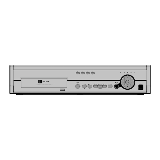
4-Channel Digital Video Recorder Chapter 3 ─ Configuration NOTE: Your DVR should be completely installed before proceeding. Refer to Chapter 2 ─ Installation. Front Panel Controls Figure 3 ─ DVR front panel. Camera Buttons HDD LED Alarm Out LED Network LED... -
Page 18: Network Led
User’s Manual Network LED The Network LED is lit when the unit is connected to a network via Ethernet. Clip Copy LED The Clip Copy LED is lit when the DVR is clip-copying. Power LED The Power LED is lit when the unit is On. PANIC Button Pressing the button starts panic recoding of all camera channels, and displays... -
Page 19: Playback Button
4-Channel Digital Video Recorder PLAYBACK Button Pressing the button enters the playback mode, and pressing the button again exits the playback PLAYBACK mode. When entering the playback mode, video is paused. Pressing the arrow button plays back video at regular speed. The screen displays when the DVR is in the Pause mode and the screen displays when the DVR is playing back video. -
Page 20: Turning On The Power
User’s Manual Turning on the Power Connecting the power cord to the DVR turns on the unit. The unit takes approximately 60 seconds to initialize. Initial Unit Setup Before using your DVR for the first time, you will want to establish the initial settings. This includes items such as time and date, display language, camera, audio, remote control, record mode, network and password. -
Page 21: System Information
4-Channel Digital Video Recorder Use the arrow keys to highlight the character you want in the name or title and press the button. That character appears in the title bar and the cursor moves to the next position. Pressing toggles between the upper and... -
Page 22: Figure 8 ─ Upgrade Screen
User’s Manual To upgrade the software, connect a USB device containing the upgrade package file to the DVR. Highlight Upgrade… and press the button. The Upgrade screen appears. The screen displays the upgrade package file names that are available. The “.rui” indicates that the file is for software upgrades and “.ofi” indicates that the file is for optical drive firmware upgrades. -
Page 23: Date/Time Setup
4-Channel Digital Video Recorder The System Log screen lists system activities (up to 5,000 from the latest) that have occurred along with the time and date. The icon will be displayed in the last column for system activities of the remote site. You can scroll... -
Page 24: Figure 13 ─ Holiday Setup Screen
User’s Manual Highlight the Format box beside Time and press the button. Select from the three available time formats and press the button to save your selected format. NOTE: The clock will not start running until you have highlighted Save and pressed the button. -
Page 25: Storage Screen
4-Channel Digital Video Recorder Highlight the box beside Automatic Sync. and press the button. This toggles between On and Off. Highlight the box beside Time Server and press the button. A virtual keyboard appears that you can use to enter the IP address or domain name of the time server. -
Page 26: User Setup Screen
User’s Manual NOTE: When the storage condition is Bad, the Event Status – Storage screen displays and you can check the storage condition for details. Once the “Bad” message displays, replacing the hard disk drive is recommended, usually within 24 hours. NOTE: Temperature and S.M.A.R.T. -
Page 27: Figure 17 ─ New Group Setup Screen
4-Channel Digital Video Recorder To add a Group, highlight the + Group… box and press the button. A virtual keyboard appears allowing you to enter the Group name. You can use up to 15 characters including spaces in the group name. -
Page 28: Shutdown Screen
User’s Manual Highlighting the box beside Auto Login allows you to select a User to be automatically logged in when the DVR is powered up. It can also be set to never automatically login a user. Highlighting the box beside Auto Logout allows you to select from a list of times that the user will be automatically logged out. -
Page 29: Lan Setup Screen
4-Channel Digital Video Recorder Figure 22 ─ Network setup screen. Highlight the first box beside Transfer Speed. Press the Up and Down arrow buttons to set the Transfer Speed from 50Kbps to 100Mbps. Highlight the second box beside Transfer Speed. You can select the unit of measure for the transfer speed between: bps and ips. -
Page 30: Figure 23 ─ Lan (Manual) Setup Screen
User’s Manual Figure 23 ─ LAN (Manual) setup screen. Highlight the box beside Type and press the button. You can select the type of network configuration from: Manual, DHCP and ADSL (with PPPoE). Select the desired type and press the button. -
Page 31: Figure 25 ─ Lan (Dhcp) Setup Screen
4-Channel Digital Video Recorder CAUTION: When changing the port settings, you must change the port settings on the PC running RAS or WebGuard as well. Refer to the RAS manual for details. Selecting DHCP from the Type and highlighting Save button reads the current IP address of the DVR configured by DHCP (Dynamic Host Configuration Protocol) network. -
Page 32: Dvrns Setup
User’s Manual DVRNS Setup Highlight the DVRNS tab, and the DVRNS screen displays. Figure 27 ─ DVRNS setup screen. NOTE: When LAN settings have been changed, set up the DVRNS after saving your LAN changes by highlighting Save and pressing the button. -
Page 33: Webguard Setup
4-Channel Digital Video Recorder Highlighting Save and pressing the button registers the DVR on the DVRNS server. Proper DVRNS settings will display the help desk information of the DVRNS server in the box beside Help Desk. WebGuard Setup Highlight the WebGuard tab, and the WebGuard screen displays. -
Page 34: Figure 30 ─ Authentication Setup Screen
User’s Manual Highlight Enable and press the button to toggle between On and Off. You will only be able to change the settings if Mail is enabled. Highlight the box beside SMTP Server and press the button. A virtual keyboard appears that you can use to enter the IP address or domain name of the SMTP server. -
Page 35: Configuring Devices
4-Channel Digital Video Recorder Highlight LAN and press the button to toggle between On and Off. When LAN is turned On you can change the IP addresses. Highlight the IP Address box that you want to change and press the button. -
Page 36: Audio Setup Screen
User’s Manual Figure 34 ─ Camera PTZ setup screen. NOTE: You will only be able to set up PTZ devices if the PTZ port is set to RS232 or RS485. Highlight the box in the Product column for the PTZ camera you wish to configure and press the button. -
Page 37: Alarm-Out Screen
4-Channel Digital Video Recorder Figure 37 ─ Audio setup screen. The DVR can record up to two audio inputs. Highlight the box beside the input and press the button. A list of cameras appears, and you can select which camera you want associated with that audio input. -
Page 38: Display Screen
User’s Manual The Day box allows you to select the days that the alarm schedule will be active. The choices are: Sun, Mon, Tue, Wed, Thu, Fri, Sat, M~F, Hol and All. The Range box allows you to set the time that the alarm schedule will be active in 15-minute increments from 00:00 to 24:00. -
Page 39: Figure 40 ─ Osd Margin Screen
4-Channel Digital Video Recorder Camera Title ─ The camera title displays at the top-left corner of each camera screen. Record ─ The record related icons display on each camera screen. PTZ ─ The icon displays on each PTZ camera screen. -
Page 40: Remote Control Screen
User’s Manual Remote Control Screen Highlight Remote Control in the Devices menu and press the button. The Remote Control setup screen allows you to select a port and make correct settings for a remote keyboard. Figure 42 ─ Remote Control setup screen. Highlight the box beside Port and select between None, RS232 and RS485. -
Page 41: Figure 44 ─ Record Setup Screen
4-Channel Digital Video Recorder Figure 44 ─ Record setup screen. Highlighting Recycle and pressing the button toggles between On and Off. In the Recycle mode, the DVR records over the oldest video data once all available storage space has been used. When Recycle is turned off, the DVR stops recording once all available storage space has been used. -
Page 42: Schedule Screen
User’s Manual You can save your Record settings by highlighting Save and pressing the button. Selecting Cancel exits the screen without saving the changes. Schedule Screen Highlight Schedule in the Record menu and press the button, and the Schedule setup screen appears. Figure 45 ─... -
Page 43: Figure 47 - Schedule - Settings (Advanced Mode) Setup Screen
4-Channel Digital Video Recorder Highlight the box under the Day heading and press the button to change the days that the scheduled recording will take place. Choose from: Sun, Mon, Tue, Wed, Thu, Fri, Sat, M~F, Hol and All. Highlight the box under the Range heading and press the button to change the time range that the scheduled recording will take place. -
Page 44: Pre-Event Screen
User’s Manual NOTE: When multiple events are detected at the same time from a specific channel, the DVR will record event video with the high setting values if the ips, Quality, Resolution and Dwell values of events are different from each other. However, the ips will be reset to the supported maximum value when the ips, Quality, Resolution and Dwell are all set to the highest value. -
Page 45: Event Settings
4-Channel Digital Video Recorder You can turn individual cameras On or Off for pre-event recording. The image speed can be set from 0.10 to 30.00 ips (25.00 ips PAL), and image quality can be selectable from Very High, High, Standard and Low. -
Page 46: Figure 52 ─ Alarm-In Actions Screen
User’s Manual Highlight the Actions tab, and the Alarm-In Actions setup screen appears. Figure 52 ─ Alarm-In Actions screen. You can set the actions the DVR will take whenever it senses an input on one of its alarm input connectors. Highlight the desired box under the Record heading, and press the button. -
Page 47: Motion Detection Screen
4-Channel Digital Video Recorder Motion Detection Screen Highlight Motion Detection in the Event menu and press the button. The Motion Detection setup screen appears. Figure 54 ─ Motion Detection Settings screen. Your DVR has built-in video motion detection. Video motion detection can be turned On or Off for each camera. -
Page 48: Figure 57 ─ Motion Detection Zone Menu
User’s Manual Select ─ Activates highlighted blocks to detect motion. Clear ─ Deactivates highlighted blocks so that they will not detect motion. Reverse ─ Activates inactive highlighted blocks and deactivates active highlighted blocks. Select All ─ Activates all blocks to detect motion. Clear All ─... -
Page 49: Figure 60 ─ Motion Detection Actions Screen
4-Channel Digital Video Recorder Figure 60 ─ Motion Detection Actions screen. The DVR can be set to react to motion detection differently for each camera. Each camera can be associated with another camera, trigger an Alarm-Out connector, sound the DVR’s internal buzzer, notify a number of different devices, and/or move PTZ cameras to preset positions. -
Page 50: Video Loss Screen
User’s Manual Video Loss Screen Highlight Video Loss in the Event menu and press the button. The Video Loss setup screen appears. Figure 61 ─ Video Loss Settings screen. The DVR checks to see if anything is obscuring the camera. Highlight the slider bar beside Check Obscuration, and use the Left and Right arrow buttons to adjust the setting. -
Page 51: Text-In Screen
4-Channel Digital Video Recorder Highlight the box under the Alarm-Out heading and press the button. Select between Alarm Output and Beep (DVR’s internal buzzer) that you would like to activate and to sound whenever the DVR detects video loss on the selected camera. -
Page 52: Figure 64 ─ Text-In Device Settings Screen
User’s Manual Figure 64 ─ Text-In Device Settings screen. Highlight the box beside Port, and press the button. Select from None, RS232, RS485 and USB-Serial (1~4). NOTE: If you have set the Port as None, you will not be able to make any changes to the screen. NOTE: When using the USB to serial text-in device, do NOT remove the USB cable from the port while the system is running. -
Page 53: Figure 65 ─ Text-In Actions Screen
4-Channel Digital Video Recorder Highlight the box beside Ignore String, and press the button. Use the virtual keyboard to enter any strings of text that you want the DVR to ignore. Refer to the device manufacturer’s documentation for text strings that the device sends during transactions, so you will know which ones you do not want recorded. -
Page 54: System Event Screen
User’s Manual Highlight the desired box under the PTZ heading, and press the button. A list of PTZ presets appear. Select the preset positions for each PTZ camera, where you want PTZ cameras to move to when the DVR detects text input. You can save your Text-In changes by highlighting Save and pressing the button. -
Page 55: Figure 68 ─ Storage Screen
4-Channel Digital Video Recorder Highlight the Storage tab and the Storage screen displays. Figure 68 ─ Storage screen. Highlight the box beside Disk Bad Notify, and press the button. Select percentage level of bad disk sectors at which you want the DVR to trigger an alert. Percentage levels range from 10% to 90%. -
Page 56: Event Status Screen
User’s Manual The DVR can be set to react to system events. System events can activate the Alarm-Out connector, sound the DVR’s internal buzzer, and/or notify a number of different devices. Highlight the Alarm-Out box beside the desired event (Check Recording, Check Alarm-In, Disk Almost Full, Disk Full, Disk Bad, Disk Temperature, or Disk S.M.A.R.T.), and press the button. - Page 57 4-Channel Digital Video Recorder Panic Record will be highlighted while the DVR is in the panic recording mode. Disk Almost Full will be highlighted when the DVR is not in the Recycle mode and the level of disk usage reaches the Disk Almost Full percentage you made in the System Event setup screen on the Event menu.
- Page 58 User’s Manual...
-
Page 59: Chapter 4 ─ Operation
4-Channel Digital Video Recorder Chapter 4 ─ Operation NOTE: This chapter assumes your DVR has been installed and configured. If it has not, please refer to Chapters 2 and 3. The DVR’s controls are similar to a VCR. As with a VCR, the main functions are recording and playing back video. -
Page 60: Sequence Mode
User’s Manual NOTE: Any image adjustments you make will be applied to both the live video on the monitors and the recorded video. Sequence Mode Pressing the button causes the cameras to display sequentially. Pressing the button SEQUENCE SEQUENCE or one of the camera buttons exits the Sequence mode. Event Monitoring When an event occurs, the DVR will display the camera associated with the event if Event Monitoring On is selected in the Display setup screen (OSD tab). -
Page 61: Figure 72 ─ Ptz Menu
4-Channel Digital Video Recorder Set the feature you wish to control by selecting it from the menu. Refer to the camera manufacturer’s instructions for the proper settings. Depending on the camera specifications, some features may not be supported. Figure 72 ─ PTZ menu. -
Page 62: Using A Mouse
User’s Manual Using a Mouse You can use a mouse instead of the front panel buttons to perform many of the DVR functions. The following operations are supported when using a mouse during live monitoring. When in quad (2x2) display mode, clicking the mouse button on a camera image switches that camera to full screen. -
Page 63: Recording Audio
4-Channel Digital Video Recorder Although you will be able to record without changing the unit from its original factory settings, you will want to take advantages of the DVR’s many tools. See Chapter 3 ─ Configuration for detailed descriptions of the recording mode options. -
Page 64: Searching Video
User’s Manual The individual controls on the toolbar perform the following functions as described below: Go to the first image Fast backward play Go to the previous image Play Go to the next image Fast forward play Go to the last image Searching Video Pressing the button or clicking the right mouse button while in the Playback mode displays the... -
Page 65: Record Table Search
4-Channel Digital Video Recorder Move the cursor over the date and time and press the (Play/Pause) button. You can use the Left and Right arrow buttons to highlight the year, month, day, hours, minutes and seconds. Use the Up and Down arrow buttons to change to the date and time you want to search for video. -
Page 66: Event Log Search
User’s Manual Selecting located at the bottom displays the Search menu. Selecting located at the bottom displays the Calendar Search screen. Days with recorded video display on the calendar with white numbers. You can highlight the days with recorded video by using the arrow buttons. -
Page 67: Figure 84 ─ Event Log Search Option Screen
4-Channel Digital Video Recorder You can search video from the first to last recorded images, or you can set the start and stop times and dates. Highlight the box beside From and press the button to toggle between On and Off. When set to Off, you can enter a specific Date and Time. -
Page 68: Text-In Search
User’s Manual Text-In Search Figure 85 ─ Text-In Search screen. The DVR maintains a log of each time there is Text Input. The Text-In Search screen displays this list. Use the arrow buttons to highlight the event for which you would like to see video. Pressing the (Play/Pause) button will extract the video associated with the Text Input and display the first image of the event. -
Page 69: Motion Search
4-Channel Digital Video Recorder NOTE: The following description is for a Generic Text device. The screen changes for different types of text input devices, and there will be different parameter boxes for you to enter information. Highlighting the + and pressing the button allows you to add a new set of search parameter. -
Page 70: Clip-Copy Screen
User’s Manual You can search video from the first to last recorded images, or you can set the start and stop times and dates. Highlight the box beside From and press the button to toggle between On and Off. When set to Off, you can enter a specific Date and Time. -
Page 71: Figure 89 ─ Clip-Copy Screen
4-Channel Digital Video Recorder Pressing the button during the playback will set the starting point of the video to be clip copied, CLIP COPY and the icon displays at the bottom-left corner of the screen. Pressing and holding the button... - Page 72 User’s Manual The DVR automatically assigns a file name to the video clip. However, you can give the video clip file a different name. Highlight the box beside File Name and press the button. A virtual keyboard appears. Enter a file name for the video you are backing up and select Close. The DVR will automatically add the camera number (for example “01”) and “.exe”...
-
Page 73: Appendix A ─ Usb Hard Disk Drive Preparation
4-Channel Digital Video Recorder Appendix A ─ USB Hard Disk Drive Preparation Preparing the USB hard disk drive in Windows 2000 NOTE: Preparing a USB hard disk drive under Windows XP and Windows Vista is almost identical to Windows 2000. -
Page 74: Appendix B ─ Text-In Search Examples
User’s Manual Appendix B ─ Text-In Search Examples Search Example I 123456789012345678901234567890123456789012345678901234567890 Item Unit price amount ================================================== Coke 2.20 | 1(s) | $ 2.20 Fanta 2.20 | 1(s) | $ 2.20 Hotdog 3.50 | 3(s) | $ 10.50 Pepsi 1.95 | 1(s) | $ 1.95 ==================================================... - Page 75 4-Channel Digital Video Recorder In the above text-in data, you can find that the comparison value is located at 17 (Unit price, $ mark will be ignored automatically), 28 (Qty) and 40 (amount) characters (including spaces) from the left, but the value of amount category is located on a different line from Item.
-
Page 76: Appendix C ─ Webguard
User’s Manual Appendix C ─ WebGuard WebGuard allows you to access a remote DVR, monitor live video images and search recorded video using Internet Explorer web browser anytime from virtually anywhere. Computer system requirements for using the WebGuard program are: ®... -
Page 77: Web Monitoring Mode
4-Channel Digital Video Recorder NOTE: When running WebGuard in the Microsoft Windows Vista operating system, it is recommended to start Internet Explorer with elevated administrator permissions. Click the right mouse button on the Internet Explorer icon and select the Run as administrator option from the context menu. Otherwise, some functions of WebGuard might be limited. -
Page 78: Web Search Mode
User’s Manual Click the camera button (1 to 4) to select the camera to be viewed. ⑥ Click the to adjust the brightness, contrast, saturation and hue of monitoring image. ⑦ Click the to control pan, tilt and zoom of the camera from a remote site. ⑧... -
Page 79: Figure 92 ─ Websearch Screen
4-Channel Digital Video Recorder Figure 92 ─ WebSearch screen. Click the to log out the WebGuard program. ① Click the to access to the web monitoring mode. ② Position the mouse pointer on the WebSearch logo to see the version of the WebGuard program. - Page 80 User’s Manual Click the to reload the recording data. ⑫ The timetable displays recorded data of the selected camera by time (in hour segments). ⑬ Selecting a camera on the screen and clicking the right mouse button displays the text menu screen. ⑭...
-
Page 81: Appendix D ─ Troubleshooting
4-Channel Digital Video Recorder Appendix D ─ Troubleshooting Problem Possible Solution Check power cord connections. No Power Confirm that there is power at the outlet. Check camera video cable and connections. Check monitor video cable and connections. No Live Video Confirm that the camera has power. -
Page 82: Appendix F ─ Map Of Screens
User’s Manual Appendix F ─ Map of Screens... -
Page 83: Appendix G ─ System Log And Error Code Notices
4-Channel Digital Video Recorder Appendix G ─ System Log and Error Code Notices System Log Boot Up Setup Begin Panic Off Shutdown Setup End Clear All Data Restart Remote Setup Change Format Disk Upgrade Remote Setup Fail Disk Full Upgrade Fail... -
Page 84: Appendix H ─ Specifications
User’s Manual Appendix H ─ Specifications VIDEO Signal Format NTSC or PAL (Auto Detect) Video Input Composite: 4 looping inputs, 1 Vp-p, auto-terminating, 75 Ohms Monitor Outputs Composite: 1 BNC, 1 Vp-p, 75 Ohms VGA: 1 (Auto Detect) Composite: 720x480 (NTSC), 720x576 (PAL) Video Resolution VGA: 720x480@60Hz (NTSC), 720x576@75Hz (PAL) Playback/Record Speed...
Need help?
Do you have a question about the 4-channel digital video recorder and is the answer not in the manual?
Questions and answers