
Related Manuals for PACOM PDR960H-8HD


Summary of Contents for PACOM PDR960H-8HD
- Page 1 PDR960H-8HD (S84674) 12 Channel (8 Analogue / 4 IP) Hybrid Digital Video Recorder PDR960H-16HD (S84675) 20 Channel (16 Analogue / 4 IP) Hybrid Digital Video Recorder Hybrid Digital Video Recorder User Manual...
-
Page 3: Compliance Notice Of Fcc
Digital Video Recorder WARNING RISK OF ELECTRIC SHOCK DO NOT OPEN WARNING: TO REDUCE THE RISK OF ELECTRIC SHOCK, DO NOT REMOVE COVER (OR BACK). NO USER-SERVICEABLE PARTS INSIDE. REFER SERVICING TO QUALIFIED SERVICE PERSONNEL. The lightning flash with arrowhead symbol, within an equilateral triangle, is intended to alert the user to the presence of uninsulated "dangerous voltage"... -
Page 4: Important Safeguards
User’s Manual Important Safeguards 14. Damage requiring Service 1. Read Instructions All the safety and operating instructions should be read before the Unplug this equipment from the wall outlet and refer servicing to appliance is operated. qualified service personnel under the following conditions: A. -
Page 5: Table Of Contents
Digital Video Recorder Table of Contents Chapter 1 — Introduction ......................1 Feature ..........................1 Technical Overview ......................1 Chapter 2 — Installation ......................3 Package Contents ........................ 3 Required Installation Tools ....................3 Video Input ........................3 Video Loop Through ......................4 eSATA Port ........................ - Page 6 User’s Manual Monitoring ........................19 Recording Setup ........................ 20 General .......................... 20 Schedule ........................22 Pre-Event ........................24 Archive ........................... 25 Network Setup ........................26 General .......................... 26 IP Address ........................28 FEN ..........................30 RTSP ..........................31 Notification ........................32 Event Setup ........................
- Page 7 Digital Video Recorder Search Menu ......................... 63 Event Log Search ......................64 Record Table Search ..................... 66 Motion Search ........................ 68 Text-In Search ....................... 69 Bookmarks ........................70 Clip-Copy ........................71 Print ..........................73 Disk Mirroring ........................73 Appendix ..........................75 USB Hard Disk Drive Preparation ..................
- Page 8 User’s Manual Figure 19 : Network – IP Address (Manual) setup screen............... 28 Figure 20 : Network – FEN setup screen....................30 Figure 21 : Network – RTSP setup screen....................31 Figure 22 : Network – Notification setup screen..................32 Figure 23 : Event –...
-
Page 9: Chapter 1 - Introduction
Digital Video Recorder Chapter 1 — Introduction Feature Your color digital video recorder (DVR) provides recording capabilities for eight or 16 camera inputs. It provides exceptional picture quality in both live and playback modes, and offers the following features: NOTE: Your DVR can record both analog CCTV video input and network video input. For a list of supported network devices (network cameras and network video transmitters), contact your installer or distributer. -
Page 10: Figure 1 : Typical Dvr Installation
User’s Manual The DVR can be set up to alert you when the hard disk drive is full, or it can be set to record over the oldest video once the disk is full. Your DVR supports disk mirroring functions to prevent any unexpected loss of recorded video data that might be caused by disk damage or corruption. -
Page 11: Chapter 2 - Installation
Digital Video Recorder Chapter 2 — Installation Package Contents The package contains the following: Digital Video Recorder Power Cord User’s Manual (This Document) RAS Software CD and User’s Manual Rack-mount Kit Assembly Screws for Adding Hard Disk Drives ... -
Page 12: Video Loop Through
User’s Manual Video Loop Through If you would like to connect your video source to another device, you can use the Loop BNC connectors. NOTE: The Loop BNC connectors are auto terminated. Do NOT connect a cable to the Loop BNC unless it is connected to a terminated device because it will cause poor quality video. -
Page 13: Rs232C Port
Digital Video Recorder GND (Ground): Connect the ground side of the Alarm input and/or alarm output to the GND connector. NOTE: All the connectors marked GND are common. NC/NO (Relay Alarm Outputs): The DVR can activate external devices such as buzzers or lights. Connect the device to the C (Common) and NC (Normally Closed) or C and NO (Normally Open) connectors. -
Page 14: Power Cord Connector
User’s Manual Power Cord Connector Connect the AC power cord to the DVR and then to a wall outlet. WARNING: ROUTE POWER CORDS SO THAT THEY ARE NOT A TRIPPING HAZARD. MAKE CERTAIN THE POWER CORD WILL NOT BE PINCHED OR ABRADED BY FURNITURE. DO NOT INSTALL POWER CORDS UNDER RUGS OR CARPET. -
Page 15: Chapter 3 - Configuration
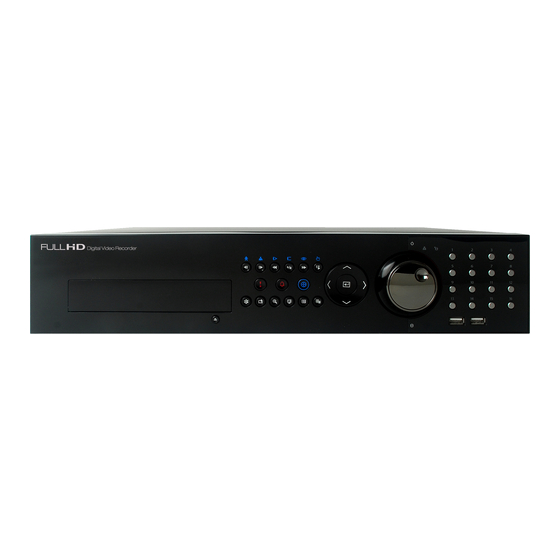
Digital Video Recorder Chapter 3 — Configuration NOTE: Your DVR should be completely installed before proceeding. Refer to Chapter 2 — Installation. Front Panel Controls Figure 3 : 16-Channel DVR front panel. Camera Buttons Jog Dial, Shuttle Ring Enter Button Arrow Buttons Playback Buttons PTZ Button... -
Page 16: Camera Buttons (1 To 16)
User’s Manual Figure 4 : Infrared remote control. NOTE: For simplicity, the button descriptions in this manual refer to the front panel buttons. Camera Buttons (1 to 16) Pressing the individual camera buttons will cause the selected camera to display full screen. Pressing the buttons 1 to 4 toggles the camera selection between local cameras and network cameras. -
Page 17: Enter Button
Digital Video Recorder Enter Button (Enter) button selects a highlighted item or completes an entry that you have made during system setup. Arrow Buttons These buttons are used to navigate through menus and GUI. You can also use them to change numbers by highlighting a number in the menu and using the Up and Down arrow buttons to increase or decrease the number’s value. -
Page 18: Zoom Button
User’s Manual ZOOM Button Pressing the button zooms the current image on the screen. A PIP with a rectangle temporarily displays showing ZOOM what area of the screen has been enlarged. You can use the arrow buttons to move the rectangle to another area. Monitor Button Pressing the button toggles the monitor selection between Primary (... -
Page 19: Turning On The Power
Digital Video Recorder Turning on the Power Connecting the power cord to the DVR turns on the unit. The unit takes approximately 60 seconds to initialize. Initial Unit Setup Before using your DVR for the first time, you will want to establish the initial settings. This includes items such as time and date, display language, camera, remote control, record mode, network and password. -
Page 20: Setup Screen
User’s Manual Setup Screen System Record Network Event Device Display Status Camera Figure 7 : Setup screen. Press the button or move the mouse pointer on the right edge of the screen and then select (Setup) in the MENU Live Monitoring menu to enter the setup screen. While setting up the DVR, there will be many opportunities to enter names and titles. -
Page 21: Figure 8 : System - General Setup Screen
Digital Video Recorder Figure 8 : System – General setup screen. In the General screen, you can name the site location, assign a System ID number, select the language the screens are displayed in, display software version number, upgrade the software, show the System Log, display recorded time data, and clear all data. - Page 22 User’s Manual You can import saved DVR settings or export the current DVR settings. To import saved DVR settings, connect the USB device containing the setup file (.dat) to the DVR. Highlight Setup – Import… and press the button. Select the desired setup file and press the Import button to import the selected settings and change the DVR settings accordingly.
-
Page 23: Date/Time
Digital Video Recorder After selecting Shutdown and pressing the button, a screen will appear telling you when it is safe to disconnect power. Date/Time Highlight Date/Time and press the button, and the Date/Time setup screen appears. Figure 9 : System – Date/Time setup screen. Highlight the first box beside Date and press the button. -
Page 24: User
User’s Manual Highlight the box beside Automatic Sync. and press the button. This toggles between On and Off. Highlight the box beside Time Server and press the button. A virtual keyboard appears that you can use to enter the IP address or domain name of the time server. Highlighting allows you to select your time server from a list of registered time servers. - Page 25 Digital Video Recorder The +/– column is used to collapse and expand user groups. If there is a + or – in this column, it indicates the item is a Group Name. If there is a – in front of the Group Name, it indicates that the group has been “expanded” and all of the User Names within that group are displayed below the Group Name.
-
Page 26: Storage
User’s Manual NOTE: In addition to using the front panel buttons or the infrared remote control, you can use the virtual keyboard to assign the password. To display the virtual keyboard click the button using the mouse (not supplied). Highlighting the box beside Auto Login allows you to select a User to be automatically logged in when the DVR is powered up. -
Page 27: Monitoring
Digital Video Recorder If you want to erase recorded data on the selected device, highlight Clear and press the button. You will be asked whether or not you want to delete the data. If you want to use a USB hard disk drive, highlight Use and press the button after connecting the device. -
Page 28: Recording Setup
User’s Manual Highlighting Schedule On and pressing the button toggles On and Off. When set to On, you can select the day, time range and interval that you want the DVR to run self-diagnostics on the recorder. The Interval can be selectable from 1 min. to 7 days or Never. Highlight the + and press the button to add a schedule item. - Page 29 Digital Video Recorder Highlighting Recycle and pressing the button toggles between On and Off. In the Recycle mode, the DVR records over the oldest video data once all available storage space has been used. When Recycle is turned off, the DVR stops recording once all available storage space has been used.
-
Page 30: Schedule
User’s Manual Schedule Highlight Schedule and press the button, and the Schedule setup screen appears. < Simple Mode > < Advanced Mode > Figure 14 : Record – Schedule setup screen. You can program the DVR to record only during certain times based on time, day of the week, and holidays. The smallest time segment you can use is 15 minutes. -
Page 31: Figure 15 : Schedule - Settings (Advanced Mode) Setup Screen
Digital Video Recorder Highlight the box under the Settings heading and press the button to define the recording settings. Figure 15 : Schedule – Settings (Advanced Mode) setup screen. You can set the ips, Quality and Resolution (ips, Quality, Resolution and Dwell for Advanced Mode setup) of the recording for any modes you set up in the Mode column. -
Page 32: Pre-Event
User’s Manual Highlighting boxes under Quality and pressing the button allows you to set the recorded image quality for Time and Event recording. You can select from: Very High, High, Standard and Basic. Highlighting boxes under Resolution and pressing the button allows you to set the recorded image resolution for Time and Event recording. -
Page 33: Archive
Digital Video Recorder Archive Highlight Archive and press the button, and the Archive setup screen appears. Figure 17 : Record – Archive setup screen. Highlight Archive On and press the button to toggle between On and Off. NOTE: If you have not set up a storage device for archiving, a message appears notifying you of this. Select the Days and Time Range you want archived. -
Page 34: Network Setup
User’s Manual Network Setup General Highlight General and press the button, and the General setup screen displays. Figure 18 : Network – General setup screen. You can limit the network bandwidth settings so that system does not consume too much network bandwidth. Highlight the box beside Network Bandwidth Limit and press the Up and Down arrow buttons to set the desired maximum bandwidth from 50Kbps to 1Gbps. - Page 35 Digital Video Recorder NOTE: The higher Quality and Resolution settings require higher Transfer Speed settings. The transfer speed you set is the maximum speed. Depending on the network environment, this speed may not be achieved. Highlight WebGuard – Use WebGuard Service and press the button to toggle between On and Off.
-
Page 36: Ip Address
User’s Manual IP Address Highlight IP Address and press the button, and the IP Address setup screen displays. Figure 19 : Network – IP Address (Manual) setup screen. Highlight the box beside Type and press the button. You can select the type of network configuration from: Manual, DHCP and ADSL (with PPPoE). - Page 37 Digital Video Recorder Highlight Use UPnP and press the button to toggle between On and Off. When it is On, port forwarding from the NAT (Network Address Translation) device to the DVR will be enabled automatically via UPnP (Universal Plug and Play) service.
-
Page 38: Fen
User’s Manual Highlight FEN and press the button, and the FEN setup screen displays. Figure 20 : Network – FEN setup screen. Highlight Use FEN and press the button to toggle between On and Off. NOTE: FEN is the technology that automatically sets up your DVR to work seamlessly for remote viewing via your network internet connection. -
Page 39: Rtsp
Digital Video Recorder RTSP Highlight RTSP and press the button. The RTSP setup screen displays. Figure 21 : Network – RTSP setup screen. Highlight Enable RTSP (Real-Time Streaming Protocol) and press the button to toggle between On and Off. You will be able to change the settings if Enable RTSP is enabled. -
Page 40: Notification
User’s Manual Notification Highlight Notification and press the button. The Notification setup screen displays. Figure 22 : Network – Notification setup screen. You can add and edit notification schedules. Highlight the + and press the button to add a schedule. Highlighting the boxes under the Column heading and pressing the button allows you to edit the information in those boxes. - Page 41 Digital Video Recorder Highlight the box under the No. heading and press the button to toggle between On and Off. You will only be able to change the IP addresses if No. is enabled. Highlight the IP Address box that you want to change and press the button.
-
Page 42: Event Setup
User’s Manual Highlight the box beside Authentication and press the button. An Authentication screen appears. Highlight Use and press the button to toggle between On and Off. Highlight the box beside User/Password and press the button. A virtual keyboard appears allowing you to enter the user ID and password. NOTE: This product includes software developed by the OpenSSL Project for use in the OpenSSL Toolkit (http://www.openssl.org/). -
Page 43: Figure 23 : Event - Motion Setup Screen
Digital Video Recorder Figure 23 : Event – Motion setup screen. Your DVR has built-in video motion detection. Video motion detection can be turned On or Off for each camera. Highlighting the box under the Sensitivity heading and pressing the button allows you to adjust the DVR’s sensitivity to motion for Daytime and Nighttime independently. -
Page 44: Alarm-In
User’s Manual Highlight the box under the Actions and press the button. The DVR can be set to react to motion detection differently for each camera. Each camera can be associated with another camera, trigger an Alarm-Out connector, sound the DVR’s internal buzzer, notify a number of different devices, move PTZ cameras to preset positions, and/or display a camera on a SPOT monitor. -
Page 45: Video Loss
Digital Video Recorder Video Loss Highlight Video Loss and press the button, and the Video Loss setup screen appears. (Local Cameras Only) Figure 25 : Event – Video Loss setup screen. Highlight the box under the Actions and press the button. -
Page 46: Text-In
User’s Manual Highlighting the box under the Sensitivity heading allows you to adjust the DVR’s sensitivity to video blind for Black and White independently from 0 and 1 (least sensitive) to 10 (most sensitive). NOTE: Video blind might NOT be detected for a camera with a very noisy image especially when set for low sensitivity values. -
Page 47: Figure 28 : Text-In Device Screen
Digital Video Recorder Figure 28 : Text-In Device screen. Highlight the box beside Port, and press the button. Select from None, RS232, RS485, USB-Serial (1~8) and LAN (1~16). NOTE: If you have set the Port as None, you will not be able to make any changes to the screen. When using the USB to serial text-in device, do NOT remove the USB cable from the port while the system is running. -
Page 48: Network
User’s Manual Highlight the box under the Actions and press the button. The DVR can be set to react to text input. Text input can be associated with cameras, trigger an Alarm-Out connector, sound the DVR’s internal buzzer, notify a number of different devices, move PTZ cameras to preset positions, and/or display a camera on a SPOT monitor. -
Page 49: Device Setup
Digital Video Recorder Device Setup Local Audio Highlight Local Audio and press the button, and the Local Audio setup screen appears. Figure 30 : Device – Local Audio setup screen. The DVR can record up to four audio inputs. Highlight the box beside the input and press the button. -
Page 50: Alarm-Out
User’s Manual Alarm-Out Highlight Alarm-Out and press the button. The Alarm-Out screen allows you to change the settings and establish a schedule for each alarm output from the DVR. Figure 32 : Device – Alarm-Out setup screen. Highlighting the box beside Dwell Time and pressing the button allows you to set the dwell time of the alarm output. -
Page 51: Remote Control
Digital Video Recorder Remote Control Highlight Remote Control and press the button. The Remote Control setup screen allows you to select a port and make correct settings for a remote keyboard. Figure 33 : Device – Remote Control setup screen. Highlight the box beside Port and select from None, RS232 and RS485. -
Page 52: Primary Monitor
User’s Manual Highlighting an item and pressing the button toggles that item On and Off. When an item is On, there is a checkmark in the box beside it. The following items can be turned On or Off: Remote Control – The icon displays when the DVR can be controlled by the infrared remote control. -
Page 53: Spot Monitor
Digital Video Recorder NOTE: Any cameras that are Off, have lost video or are set to Covert (unless the user has authority to view covert cameras) will be excluded from the Cameo sequence. You can define the screen layout in a variety of formats and set the DVR to sequence through the different screen layouts (pages) so that all the cameras will be displayed. -
Page 54: Status Setup
User’s Manual You can define which cameras display sequentially on the Spot Monitor when in the single-screen display format. Highlighting the box under the Camera and pressing the button toggles between On and Off. You can adjust the display dwell time by highlighting the box under the Dwell and pressing the button. -
Page 55: Storage
Digital Video Recorder Fan Error will be highlighted when the cooling fan to the left of the power cord on the rear panel is not working for more than four seconds. eSATA Disconnected will be highlighted when the eSATA device is disconnected. Storage Highlight Storage and press the button, and the Storage setup screen appears. -
Page 56: Camera Setup
User’s Manual Camera Setup General Highlight General and press the button, and the General setup screen appears. (Local Cameras Only) Figure 39 : Camera – General setup screen. You can turn the camera number On or Off, and you can change the Title of each camera using the virtual keyboard. You can also determine which cameras will display on the monitors by selecting Normal, Covert 1 or Covert 2 from a drop-down list in the Use column. -
Page 57: Network Camera
Digital Video Recorder Figure 40 : Camera – PTZ setup screen. NOTE: You will only be able to set up PTZ devices if the PTZ port is set to RS232 or RS485. Highlight the box in the Product column for the PTZ camera you wish to configure and press the button. -
Page 58: Figure 41 : Camera - Network Camera Setup Screen
User’s Manual Figure 41 : Camera – Network Camera setup screen. Highlight the Scan… box and press the button, and the Device Scan setup screen appears. Highlighting the box beside Protocol and pressing the button allows you to select the protocol for the network device you want to search. - Page 59 Digital Video Recorder Selecting Auto Scan (LAN) from Mode scans network devices automatically. Selecting IP Address Scan from Mode scans network devices by entering a specific IP address or adjusting the IP address range. Highlighting Port and pressing the button allows you to set the port number used for remote monitoring. Selecting FEN Scan from Mode scans network devices by entering the IP address or domain name of the network device.
- Page 60 User’s Manual Highlight the box beside User/Password and press the button. A virtual keyboard appears allowing you to enter the user ID and password. Highlight Apply to All Devices and press the button to apply the same authentication information to all the network devices in the list. When selecting multiple network devices in the list, selecting Skip skips the authentication settings for the current network device and displays the Authentication screen of the next network device.
- Page 61 Digital Video Recorder Highlight Use Audio Recording and press the button to toggle between On and Off. When it is On, the DVR will record audio from the device when the video from the network device is recording. Highlight the Device Remote Setup box and press the button.
- Page 62 User’s Manual Highlighting the box beside Stream Protocol and pressing the button allows you to select the protocol for streaming. Highlighting the box beside Record Protocol and pressing the button allows you to select the protocol for recording. Highlighting the box beside ONVIF Profile and pressing the button allows you to select a preset ONVIF profile.
-
Page 63: Chapter 4 - Operation
Digital Video Recorder Chapter 4 — Operation NOTE: This chapter assumes your DVR has been installed and configured. If it has not, please refer to Chapters 2 and 3. The DVR’s controls are similar to a VCR. As with a VCR, the main functions are recording and playing back video. However, you have much greater control over recording and playing back video. -
Page 64: Live Monitoring Menu
User’s Manual Live Monitoring Menu Login/Logout Selecting (Login) in the Live Monitoring menu accesses the Login screen, and you will be asked to select a User and enter the password to log into the system. Selecting (Logout) in the Live Monitoring menu displays the Logout screen asking you to confirm whether or not you want to log out the current user. -
Page 65: Camera Menu
Digital Video Recorder Sequence Selecting (Sequence) in the Live Monitoring menu causes the cameras to display sequentially. It is the same as pressing the button on the remote control. When in one of the multi-view formats, selecting will cause SEQUENCE the DVR to go through predefined screen layouts (Full Sequence). -
Page 66: Active Cameo Mode
User’s Manual Active Cameo Mode You can enter the Active Cameo mode by selecting Edit Group from the Live Monitoring – Display menu or pressing button on the front panel in any multi-view format. The yellow outline surrounding the video indicates the active cameo, and pressing the arrow buttons moves the active cameo. -
Page 67: Event Monitoring
Digital Video Recorder You can save camera position settings as “presets” so that you can go directly to desired views. Once you have the camera at the desired settings, press the button, and the Set Preset dialog box will appear. Select the number you want to assign to the preset and press the button. -
Page 68: Covert Camera
User’s Manual Covert Camera If a camera is set up as Covert 1 in the Camera setup screen (General tab), that camera will not be displayed unless a user with Covert Camera View authority logs into the system. However the camera title and status icons will be displayed on the monitor. -
Page 69: Panic Recording
Digital Video Recorder Panic Recording Selecting (Panic) in the Live Monitoring menu or Search menu, or pressing the button starts panic recording PANIC of all cameras. Selecting or pressing the button again stops panic recording. If you set the Panic Recording Duration in the Panic Record setup screen, panic recording will stop automatically according to the preset duration as long as is not selected or the button is not pressed. -
Page 70: Searching Video
User’s Manual Playback Buttons Backward: When in the pause mode, pressing the button moves to the previous image. Forward: When in the pause mode, pressing the button moves to the next image. Rewind: Pressing the button plays video backward at high speed. Pressing the button again toggles the playback speed from ... -
Page 71: Search Menu
Digital Video Recorder NOTE: The Search menu also can be displayed by moving the mouse pointer to the right edge of the screen. Search Menu Search Event Log Search: Selecting (Search) → Event Log Search selects video from the event log. See the following Event Log Search section for details. -
Page 72: Event Log Search
User’s Manual Panic Selecting (Panic) in the Search menu starts panic recording of all cameras, and selecting again stops panic recording. It is the same as pressing the button. PANIC Camera Menu Zoom: Selecting (Camera Menu) → Zoom and choosing the camera number zooms the current playback image of the selected camera on the screen. - Page 73 Digital Video Recorder The DVR maintains a log of each time the Alarm Input port is activated. The Event Log Search screen displays this list. Use the arrow buttons to highlight the event for which you would like to see video. The Event Log Search screen can also be accessed by pressing the button unless there is an alarm.
-
Page 74: Record Table Search
User’s Manual Highlight the box beside Text-In and press the button. You can select the text-in devices which you want any reports of text input. Highlight the box beside Record Channels and press the button. You can select the cameras that you want to search for any reports of event recorded data. - Page 75 Digital Video Recorder If the DVR’s time and date have been reset to a time that is earlier than some recorded video, it is possible for the DVR to have more than one video stream in the same time range. In this case, the overlapping time range in the record table will be separated by a yellow vertical line .
-
Page 76: Motion Search
User’s Manual Motion Search Figure 49 : Motion Search screen. The Motion Search… can be selected from the Search menu while the DVR displays the camera full screen. The Motion Search screen displays a list of motion events. Use the arrow buttons to highlight the event for which you would like to see video and press the button to display the video associated with the selected event on the small search screen. -
Page 77: Text-In Search
Digital Video Recorder The zone should be placed or focused on the centre or, at least, within the outline of targeted object. Highlight the box beside Sensitivity and press the button. You will be able to select from 1 (low sensitivity) to 5 (high sensitivity). -
Page 78: Bookmarks
User’s Manual You can search video from the first to last recorded images, or you can set the start and stop times and dates. Highlight the box beside From and press the button to toggle between On and Off. When set to Off, you can enter a specific Date and Time. -
Page 79: Clip-Copy
Digital Video Recorder Clip-Copy Video clips can be copied on an internal DVD RW drive, or external USB hard disk or flash drive. The copied video clips can be viewed on computers running Microsoft Windows 2000, XP, Vista or 7. Refer to the Appendix – USB Hard Disk Drive Preparation for information on preparing the external drive for clip copy. - Page 80 User’s Manual NOTE: While copying video clips on the DVD RW, the recording speed might decrease. When the error message “Firmware update of the optical drive is required” displays, update the firmware of the installed DVD RW drive. Please follow the instructions described in Chapter 3 – Configuration – System Setup section.
-
Page 81: Print
Digital Video Recorder Print You can print images on a printer. Connect a PostScript™ printer, or external hard disk drive or flash drive to one of the USB ports. Highlight the box beside Printer Model and press the button. Selecting PostScript Printer will print images on a PostScript™... - Page 82 User’s Manual CAUTION: Any existing data on the Destination Disk will be erased once it is designated as a mirror destination disk. Highlighting Start and pressing the button displays a confirmation screen asking you to confirm whether or not you want to start mirroring the selected disk.
-
Page 83: Appendix
Digital Video Recorder Appendix USB Hard Disk Drive Preparation NOTE: The following description is for preparing a USB hard disk drive under Windows 2000. Preparing a USB hard disk drive under Windows XP, Window Vista and Window 7 is almost identical to Windows 2000. Connect the USB hard disk drive to your computer using the USB Cable. -
Page 84: Search Example Ii
User’s Manual Search Example II 123456789012345678901234567890123456789012345678901234567890 Item Unit price amount ================================================== Coke 2.20 | 1(s) 2.20 Fanta 2.20 | 1(s) 2.20 Hotdog 3.50 | 3(s) 10.50 Pepsi 1.95 | 1(s) 1.95 ================================================== total : $ 16.85 Thank you~~ In the above text-in data, you can find that the comparison value is located at 17th (Unit price, $ mark will be ignored automatically), 28 (Qty) and 40 (amount) characters (including spaces) from the left, but the value of amount... -
Page 85: Webguard
Digital Video Recorder WebGuard WebGuard allows you to access a remote DVR, monitor live video images and search recorded video using Internet Explorer web browser anytime from virtually anywhere. Computer system requirements for using the WebGuard program are: ® ® ®... -
Page 86: Web Monitoring Mode
User’s Manual NOTE: There might be a problem with screen display or screen update due to low image transmission speed when using the Microsoft Windows Vista or higher operating system. In this situation, it is recommended that you disable the Auto Tuning capability of your computer. Run the Command Prompt with elevated administrator permissions (Go to the Start Menu →... -
Page 87: Web Search Mode
Digital Video Recorder ⑩ Click the to set up the image drawing mode, OSD display and beep on/off. You can adjust the display speed by changing the image drawing mode, select OSD information to be displayed on the screen, and turn the DVR’s internal buzzer on and off from a remote site. -
Page 88: Time Overlap
User’s Manual ⑤ Click the to blur, sharpen, equalize and interpolate playback images. Click the to zoom out or zoom in the recorded image. Click the to adjust the brightness of the recorded images. NOTE: Image processing works only in the pause mode. ⑥... -
Page 89: Remote Setup Of Network Devices
Digital Video Recorder If you want to search recorded video from four to five o’clock during the overlapping time range using a search menu such as Event Log Search, Text-In Search or Motion Search, it is possible for the DVR to have two overlapping start and stop times. - Page 90 User’s Manual System Setup Information: Displays the device information. Maintenance: Restarts the device or returns all device settings to the original factory settings. Security Setup User: Adds or deletes a user. Media Setup ONVIF Profile: Adds or deletes an ONVIF profile.
- Page 91 Digital Video Recorder Network Setup TCP/IP: Sets up the device’s IP address and DNS server. DDNS: Sets up the DDNS function. Zero Configuration: Automatically allocates an appropriate IP address for the current network conditions (supported only for devices that provide the function). ...
-
Page 92: Connector Pin Outs
User’s Manual PTZ Setup PTZ: Sets up the PTZ. Connector Pin Outs I/O Connector Pin Outs AI (1 to 16) Alarm Inputs 1 to 16 Chassis Ground (5 connectors) Relay Alarm Output (Normally Closed) Relay Common Relay Alarm Output (Normally Open) Alarm Reset In RS485 Connector Pin Outs Master Unit... -
Page 93: Map Of Screens
Digital Video Recorder Map of Screens MENU SYSTEM General Date/Time User Storage Monitoring RECORD General Schedule Pre-Event Archive NETWORK General IP Address RTSP Notification EVENT Motion Alarm-In Video Loss Video Blind Text-In Network DEVICE Local Audio Network Audio Alarm-out Remote Control DISPLAY Primary Monitor Spot Monitor... -
Page 94: Error Code Notices
User’s Manual Error Code Notices System Upgrade Related Clip Copy Related Description Description Unknown error. Unknown error. File version error. Device error. Operating system version error. Mounting failed. Software version error. No media. Kernel version error. Invalid media. Upgrade device mounting failed. File already existed. -
Page 95: System Log Notices
Digital Video Recorder System Log Notices Boot Up Setup Exported Clip-Copy From: Shutdown Setup Export Failure Clip-Copy To: Restart Setup Export Cancel Clip-Copy Duration of Video: Upgrade Schedule On Clip-Copy Camera: Upgrade Fail Schedule Off Callback Fail Power Failure Panic On Print Begin Time Change Panic Off... -
Page 96: Specifications
User’s Manual Specifications VIDEO Signal Format NTSC or PAL (Auto Detect) Local Composite: 8 or 16 looping inputs, 1 Vp-p, auto-terminating, 75 Ohms Video Input Network 4 network devices (100Mbps/1Gbps Ethernet) HDMI: 1 HDMI Monitor Outputs VGA: 1 SPOT: 1 BNC, 1 Vp-p, 75 Ohms HDMI/VGA: 1920x1080p, 1920x1080i, 1280x1024, 1024x768 Video Resolution Composite (SPOT): 704x480 (NTSC), 704x576 (PAL) - Page 97 Digital Video Recorder GENERAL Dimensions (W x H x D) 16.9" x 3.5" x 15.7" (430mm x 88mm x 400mm) Unit Weight 17.9 lbs. (8.1kg) Shipping Weight 24.5 lbs. (11.1kg) Shipping Dimensions 21.3" x 11.4" x 23.2" (540mm x 290mm x 590mm) (W x H x D) Operating Temperature 41°F to 104°F (5°C to 40°C)
- Page 99 Before making a warranty claim, ensure that you have read the “Troubleshooting” section of the Owner’s Manual. PACIFIC COMMUNICATIONS A division of Hills Holdings Limited ACN 007 573 417 Unit 10, 331 Ingles Street City Link Estate, PORT MELBOURNE VIC 3207, AUSTRALIA www.pacom.com.au...
- Page 100 WARRANTY TERMS Pacific Communications provides consumers with the following warranty in relation to this Equipment, in addition to complying with the requirements of any relevant legislation, including the Competition and Consumer Act 2010 (Cth) in Australia and the Consumer Guarantees Act 1993 in New Zealand (the Acts), except where a New Zealand consumer acquires the relevant Product for the purposes of a business.
- Page 102 ISO 14001 Fibre sourced from Environmental pulp suppliers who Management use sustainable System in use. forestry techniques. V1.0...
Need help?
Do you have a question about the PDR960H-8HD and is the answer not in the manual?
Questions and answers