
Subscribe to Our Youtube Channel
Related Manuals for PACOM PDR960H-8RT


Summary of Contents for PACOM PDR960H-8RT
-
Page 1: Digital Video Recorder
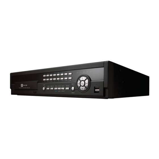
PDR960H-8RT (S84676) 8 Channel Digital Video Recorder PDR960H-16RT (S84677) 16 Channel Digital Video Recorder Digital Video Recorder User Manual... -
Page 3: Compliance Notice Of Fcc
Digital Video Recorder WARNING RISK OF ELECTRIC SHOCK DO NOT OPEN WARNING: TO REDUCE THE RISK OF ELECTRIC SHOCK, DO NOT REMOVE COVER (OR BACK). NO USER-SERVICEABLE PARTS INSIDE. REFER SERVICING TO QUALIFIED SERVICE PERSONNEL. The lightning flash with arrowhead symbol, within an equilateral triangle, is intended to alert the user to the presence of uninsulated "dangerous voltage"... -
Page 4: Important Safeguards
User’s Manual Important Safeguards 14. Damage requiring Service 1. Read Instructions All the safety and operating instructions should be read before the Unplug this equipment from the wall outlet and refer servicing to appliance is operated. qualified service personnel under the following conditions: A. -
Page 5: Table Of Contents
Digital Video Recorder Table of Contents Chapter 1 — Introduction ......................1 Feature ..........................1 Technical Overview ......................1 Chapter 2 — Installation ......................3 Package Contents ........................ 3 Required Installation Tools ....................3 Video Input ........................3 Video Loop Through ......................3 Audio In/Out ........................ - Page 6 User’s Manual System Event ......................... 25 Recording Setup ........................ 26 General .......................... 26 Schedule ........................27 Pre-Event ........................29 Event Setup ........................30 Motion ..........................30 Alarm-In ......................... 31 Video Loss ........................32 Video Blind ........................33 Text-In ........................... 34 Camera Setup ........................
- Page 7 Digital Video Recorder Search Menu ......................... 63 Event Log Search ......................65 Record Table Search ..................... 66 Motion Search ........................ 68 Text-In Search ....................... 69 Bookmarks ........................71 Clip-Copy ........................71 Print ..........................73 Appendix ..........................75 USB Hard Disk Drive Preparation ..................75 Preparing the USB hard disk drive in Windows 2000 .............
- Page 8 User’s Manual Figure 24: Device – Audio setup screen....................38 Figure 25: Device – Alarm-Out setup screen..................38 Figure 26: Device – Remote Control setup screen................. 39 Figure 27: Network – General setup screen.................... 40 Figure 28: Network – LAN setup screen....................41 Figure 29: Network –...
-
Page 9: Chapter 1 - Introduction
Digital Video Recorder Chapter 1 — Introduction Feature Your color digital video recorder (DVR) provides recording capabilities for eight or 16 camera inputs. It provides exceptional picture quality in both live and playback modes, and offers the following features: 8 or 16 Composite Video Input Connectors ... -
Page 10: Figure 1: Typical Dvr Installation
User’s Manual You can view video and control your DVR remotely by connecting via Ethernet. There are two USB ports that can be used to upgrade the system or copy video clips to external hard disk and flash drives, and there is an eSATA port that can be used to record video to an external hard disk drive. -
Page 11: Chapter 2 - Installation
Digital Video Recorder Chapter 2 — Installation Package Contents The package contains the following: Digital Video Recorder Power Cord User’s Manual (This Document) RAS Software CD and User’s Manual Rack-mount Kit Assembly Screws for Adding Hard Disk Drives ... -
Page 12: Audio In/Out
User’s Manual NOTE: The Loop BNC connectors are auto terminated. Do NOT connect a cable to the Loop BNC unless it is connected to a terminated device because it will cause poor quality video. Audio In/Out Your DVR can record audio from up to four sources. Connect the audio sources to Audio In 1, Audio In 2, Audio In 3 and Audio In 4 as needed using RCA jacks. -
Page 13: Rs485 Port
Digital Video Recorder Connector Pin Outs: AI (1 to 16) Alarm Inputs 1 to 16 Chassis Ground Relay Alarm Out (Normally Closed) Relay Common Relay Alarm Out (Normally Open) Alarm Reset In RS485 Port The DVR can be controlled remotely by an external device or control system, such as a control keyboard, using RS485 half-duplex serial communications signals. -
Page 14: Video Out
User’s Manual Video Out An HDMI (High-Definition Multimedia Interface) connector is provided so that you can use an HDMI monitor as your main monitor. A VGA connector is provided so that you can use a standard, multi-sync computer monitor as your main monitor. Use the cable supplied with your monitor to connect it to the DVR. -
Page 15: Chapter 3 - Configuration
Digital Video Recorder Chapter 3 — Configuration NOTE: Your DVR should be completely installed before proceeding. Refer to Chapter 2 — Installation. Front Panel Controls Figure 3: 16-Channel DVR front panel. Camera Buttons HDD LED Alarm Out LED Network LED Clip Copy LED Power LED Panic Button... -
Page 16: Camera Buttons (1 To 16)
User’s Manual Figure 4: Infrared remote control. NOTE: For simplicity, the button descriptions in this manual refer to the front panel buttons. Camera Buttons (1 to 16) Pressing the individual camera buttons will cause the selected camera to display full screen. Buttons 1 to 9 are also used to enter passwords. -
Page 17: Power Led
Digital Video Recorder Power LED The Power LED is lit when the unit is On. PANIC Button Pressing the button starts panic recoding of all camera channels, and displays on the screen. Pressing the PANIC button button again will stop panic recording. ALARM Button button has two functions. -
Page 18: Menu/Cameo Button
User’s Manual MENU/CAMEO Button Pressing the button enters the Setup screen. You will need to enter the authorized user and password MENU/CAMEO to access Setup. Pressing the button also closes the current menu or setup dialog box. In the Playback mode, pressing the button displays the Search menu. -
Page 19: Bookmark Button On Remote Control
Digital Video Recorder Bookmark Button on Remote Control When in the playback mode, pressing the button adds the current playback point to the bookmark list or BOOKMARK moves to the registered bookmark point. Turning on the Power Connecting the power cord to the DVR turns on the unit. The unit takes approximately 50 seconds to initialize. Initial Unit Setup Before using your DVR for the first time, you will want to establish the initial settings. -
Page 20: Setup Screen
User’s Manual Setup Screen System Record Event Camera Device Network Notification Display Figure 7: Setup screen. Press the button or move the mouse pointer on the right edge of the screen and then select (Setup) in the Live MENU Monitoring menu to enter the setup screen. While setting up the DVR, there will be many opportunities to enter names and titles. -
Page 21: Figure 8: System - General Setup Screen
Digital Video Recorder Figure 8: System – General setup screen. Highlight the Site box and press the button. A virtual keyboard appears that you can use to enter a Site Name. Once you have entered your title, highlight OK and press the button. - Page 22 User’s Manual To export the current DVR settings, connect the USB device to the DVR. Highlight Setup – Export… and press the button. Highlight the box beside File name and press the button. A virtual keyboard allows you to enter the file name.
- Page 23 Digital Video Recorder Highlight Wizard and press the button. The Wizard setup screen appears. The Wizard setup guides you through configuring the system for basic operation. Select either Quick wizard or Network wizard and select the Next button to start the selected setup wizard. NOTE: Selecting the Cancel button throughout the screens exits the Quick Setup Wizard without saving your changes and returns to the main setup screen.
- Page 24 User’s Manual Date/Time Setup Date: Set the system date and select the date format. Time: Set the system time and select the time format. Time Zone: Select your time zone. The Time Zone can be selected on the map. ...
- Page 25 Digital Video Recorder Record Video Quality Setup Select the desired video quality profile from: – Higher Video Quality Priority Profile – Standard Recording Profile – Longer Recording Time Priority Profile NOTE: The higher quality setting requires more storage space. The recording resolution will be set to Very High when selecting High Video Quality Priority Profile, High when selecting Standard Recording Profile, and Standard when selecting Longer Recording Time Priority Profile.
- Page 26 User’s Manual If you selected the Go to Network Setup, select the Next button to start the Network Setup Wizard. Internet Connection Select whether or not your DVR is connected to the Internet.
- Page 27 Digital Video Recorder LAN Setup Select between Auto Configuration and Manual Configuration for network configuration, and then select the Test button to test the network configuration you selected. NOTE: Selecting Auto Configuration allows the DVR to automatically obtain LAN parameters (IP address, Gateway, Subnet Mask and DNS Server address).
-
Page 28: Date/Time
User’s Manual Highlight System Shutdown and press the button. The Shutdown screen displays asking you to confirm whether or not you want to shut the system down. After selecting Shutdown and pressing the button, a screen will appear telling you when it is safe to disconnect power. - Page 29 Digital Video Recorder Highlight the box beside Automatic Sync. and press the button. This toggles between On and Off. Highlight the box beside Time Server and press the button. A virtual keyboard appears that you can use to enter the IP address or domain name of the time server. Highlighting allows you to select your time server from a list of registered time servers.
-
Page 30: User
User’s Manual User Figure 10: System – User setup screen. The +/– column is used to collapse and expand user groups. If there is a + or – in this column, it indicates the item is a Group Name. If there is a – in front of the Group Name, it indicates that the group has been “expanded” and all of the User Names within that group are displayed below the Group Name. - Page 31 Digital Video Recorder Highlighting the Authority box and pressing the button will toggle between all authority levels being turned On and Off. Highlighting the individual authority level boxes and pressing the button will toggle between that authority level being turned On and Off. The authority levels that can be turned On and Off are: ...
-
Page 32: Storage
User’s Manual Storage Figure 11: System – Storage setup screen. The information in the Type column describes the storage device. The capacity of the storage device is displayed in the Capacity column. The Format column displays whether the device is used for recording (Record) or not (Not Using). Not formatted indicates the device is not formatted. -
Page 33: System Event
Digital Video Recorder System Event Figure 12: System – System Event setup screen. The DVR can be configured to run self-diagnostics and report the results. Highlight the Settings box beside the desired event (System, Check Recording, Check Alarm-In, Disk Almost Full, Disk Bad, or Disk Temperature), and press the button. -
Page 34: Recording Setup
User’s Manual Highlight the Settings box beside Disk Temperature, and press the button. Select the temperature of hard disk drive at which you want the DVR to trigger an alert if the temperature exceeds the defined threshold. Refer to the hard disk drive manufacturer’s documentation for the correct temperature setting. -
Page 35: Schedule
Digital Video Recorder NOTE: When the storage device does not have enough space to record video data longer than the preset Limit Time-Lapse Recording period, the DVR records over the oldest video data (time-lapse or event video) as it would in the Recycle mode even if this feature is turned On. The maximum storage time is only an estimate because the amount of space required to store video varies depending on many factors such as motion and image complexity. -
Page 36: Figure 15: Schedule - Settings (Advanced Mode) Setup Screen
User’s Manual Highlight the + and press the button to add a schedule item. Highlight the box under the Day heading and press the button to change the days that the scheduled recording will take place. Choose from: Sun, Mon, Tue, Wed, Thu, Fri, Sat, M~F, Hol and All. Highlight the box under the Range heading and press the button to change the time range that the scheduled recording will take place. -
Page 37: Pre-Event
Digital Video Recorder Highlight the box under the heading and press the button to delete the recording settings. You will be asked to confirm that you want to delete the settings. Highlight Default… and press the button. The Default screen appears. Highlighting boxes under ips and pressing the button allows you to set the images per second for Time and Event recording. -
Page 38: Event Setup
User’s Manual Event Setup Motion Figure 17: Event – Motion setup screen. Your DVR has built-in video motion detection. Video motion detection can be turned On or Off for each camera. Highlighting the box under the Sensitivity heading and pressing the button allows you to adjust the DVR’s sensitivity to motion for Daytime and Nighttime independently. -
Page 39: Alarm-In
Digital Video Recorder You can adjust the minimum number of detection blocks that must be activated to trigger a motion alarm. Highlighting the box under the Min. Blocks heading and pressing the button allows you to adjust the minimum number of detection blocks for Daytime and Nighttime independently. Smaller numbers provide greater sensitivity because fewer detection blocks must be activated. -
Page 40: Video Loss
User’s Manual Highlight the box under the Actions and press the button. You can set the actions the DVR will take whenever it senses an input on one of its alarm input connectors. Alarm input can be associated with cameras, trigger an Alarm-Out connector, sound the DVR’s internal buzzer, notify a number of different devices, move PTZ cameras to preset positions, and/or display a camera on a SPOT monitor. -
Page 41: Video Blind
Digital Video Recorder Video Blind Figure 20: Event – Video Blind setup screen. The DVR checks to see if anything is blinding a camera. Highlighting the box under the Sensitivity heading allows you to adjust the DVR’s sensitivity to video blind for Black and White independently from 0 (Never) and 1 (least sensitive) to 15 (most sensitive). -
Page 42: Text-In
User’s Manual Text-In Figure 21: Event – Text-In setup screen. The DVR can be set to react to text input from devices such as ATMs (Automated Teller Machines) and POS (Point of Sale; i.e., cash registers). This screen allows you to configure the DVR for each text-in device. Highlight the box under the Setup heading, and press the button. - Page 43 Digital Video Recorder NOTE: The following description is for a Generic Text Device. The screen changes for different types of text input devices, and there will be different parameter boxes for you to enter information. Highlight the box beside Transaction Start, and press the button.
-
Page 44: Camera Setup
User’s Manual Camera Setup General Figure 22: Camera – General setup screen. You can turn the camera number On or Off, and you can change the Title of each camera using the virtual keyboard. You can also determine which cameras will display on the monitors by selecting Normal, Covert 1 or Covert 2 from a drop-down list in the Use column. -
Page 45: Ptz
Digital Video Recorder Figure 23: Camera – PTZ setup screen. NOTE: You will only be able to set up PTZ devices if the PTZ port is set to RS232 or RS485. Highlight the box in the Product column for the PTZ camera you wish to configure and press the button. -
Page 46: Device Setup
User’s Manual Device Setup Audio Figure 24: Device – Audio setup screen. The DVR can record up to four audio inputs. Highlight the box beside the input and press the button. A list of cameras appears, and you can select which camera you want associated with that audio input. Highlight Enable Audio-Out and press the button. -
Page 47: Remote Control
Digital Video Recorder You can add and edit alarm output schedules on this screen. Highlight the + and press the button to add a schedule. Highlighting the boxes under the Column heading and pressing the button allows you to edit the information in those boxes. -
Page 48: Network Setup
User’s Manual Network Setup General Figure 27: Network – General setup screen. Highlight the first box beside Remote Watch – bps/ips. You can select the Transfer Speed from 50Kbps to 1Gbps. Highlight the second box beside Remote Watch – bps/ips. You can select the unit of measure for the transfer speed between: bps and ips. -
Page 49: Lan
Digital Video Recorder NOTE: While the SSL function is enabled, the network transfer speed you selected may not be achieved. This product includes software developed by the OpenSSL Project for use in the OpenSSL Toolkit (http://www.openssl.org/). Figure 28: Network – LAN setup screen. Highlight the box beside Type and press the button. - Page 50 User’s Manual CAUTION: When changing the port settings, you must change the port settings on the PC running RAS as well. Refer to the RAS manual for details. Highlight Use UPnP and press the button to toggle between On and Off. When it is On, port forwarding from the NAT (Network Address Translation) device to the DVR will be enabled automatically via UPnP (Universal Plug and Play) service.
-
Page 51: Fen
Digital Video Recorder Figure 29: Network – FEN setup screen. Highlight Use FEN and press the button to toggle between On and Off. NOTE: FEN is the technology that automatically sets up your DVR to work seamlessly for remote viewing via your network internet connection. -
Page 52: Rtsp
User’s Manual RTSP Figure 30: Network – RTSP setup screen. Highlight Enable RTSP (Real-Time Streaming Protocol) and press the button to toggle between On and Off. You will be able to change the settings if Enable RTSP is enabled. Highlight the box beside RTSP Port and press the button. -
Page 53: Webguard
Digital Video Recorder WebGuard Figure 31: Network – WebGuard setup screen. Highlight Use WebGuard Service and press the button to toggle between On and Off. See Appendix – WebGuard for detailed descriptions of the WebGuard service. Highlight the box beside Port and press the button. -
Page 54: Notification Setup
User’s Manual Highlight the box beside Password and press the button. A virtual keyboard appears allowing you to enter the password for VNC connection. NOTE: Up to three users at a time can access a DVR remotely via VNC service. When controlling the DVR remotely using a keyboard, shortcut keys perform the following functions as described below: Function... -
Page 55: Mail
Digital Video Recorder Highlight the IP Address box that you want to change and press the button. Use the arrow buttons to enter the IP address of the computer you want contacted during an event. You can enter up to five IP addresses. Highlight the box beside Retry and enter the number of times you would like the DVR to try contacting the computer. - Page 56 User’s Manual Highlight Use and press the button to toggle between On and Off. Assign the Recipient to a Group and enter the Recipient’s Display Name. Highlight the box beside Address and enter the recipient’s e-mail address and mail server provider. Highlighting allows you to select the mail server provider from a list of registered SMTP mail server...
-
Page 57: Sns
Digital Video Recorder Figure 35: Notification – SNS setup screen. The DVR can be set up to post a message via SNS (Social Network Service) when an event occurs. You can add and edit the SNS account on this screen. The SNS account can be turned On or Off by highlighting the boxes under the No. -
Page 58: Display Setup
User’s Manual You can add and edit notification schedules on this screen. Highlight the + and press the button to add a schedule. Highlighting the boxes under the Column heading and pressing the button allows you to edit the information in those boxes. -
Page 59: Main Monitor
Digital Video Recorder Freeze & Sequence – The icon displays while in the Freeze mode, and the displays while in the Sequence mode. Screen Group – The number of screen group displays when the DVR is not in the 4x4 display mode of the 16-channel DVR, and 3x3 mode of the 8-channel DVR. -
Page 60: Spot Monitor
User’s Manual NOTE: Sequence cannot be used in the 4x4 display mode of the 16-channel, and 3x3 mode of the 8-channel DVR. You can adjust the display dwell time by highlighting the box beside Interval and pressing the button. You can select dwell intervals ranging from 1 second to 1 minute. -
Page 61: Chapter 4 - Operation
Digital Video Recorder Chapter 4 — Operation NOTE: This chapter assumes your DVR has been installed and configured. If it has not, please refer to Chapters 2 and 3. The DVR’s controls are similar to a VCR. As with a VCR, the main functions are recording and playing back video. However, you have much greater control over recording and playing back video. -
Page 62: Live Monitoring Menu
User’s Manual Live Monitoring Menu Login/Logout Selecting (Login) in the Live Monitoring menu accesses the Login screen, and you will be asked to select a User and enter the password to log into the system. Selecting (Logout) in the Live Monitoring menu displays the Logout screen asking you to confirm whether or not you want to log out the current user. -
Page 63: Camera Menu
Digital Video Recorder Sequence Selecting (Sequence) in the Live Monitoring menu causes the cameras to display sequentially. It is the same as pressing and holding the button for three seconds or longer. When in one of the multi-view formats, selecting SEQUENCE will cause the DVR to go through predefined screen layouts (Full Sequence). -
Page 64: Active Cameo Mode
User’s Manual Setup Selecting (Setup) in the Live Monitoring menu enters the Main Setup screen. Refer to Chapter 3 ─ Configuration for detailed descriptions of system setup. Status Selecting (Status) in the Live Monitoring menu allows you to check the status of the DVR’s system, inputs and storage. Refer to the following Status Monitoring section for details. -
Page 65: Event Monitoring
Digital Video Recorder You can save camera position settings as “presets” so that you can go directly to desired views. Once you have the camera at the desired settings, press the button, and the Set Preset dialog box will appear. Select the number you want to assign to the preset and press the (Play/Pause) button. -
Page 66: Covert Camera
User’s Manual Covert Camera If a camera is set up as Covert 1 in the Camera setup screen (General tab), that camera will not be displayed unless a user with Covert Camera View authority logs into the system. However the camera title and status icons will be displayed on the monitor. -
Page 67: Status Monitoring
Digital Video Recorder Status Monitoring Selecting (Status) in the Live Monitoring menu or Search menu displays the Event Status screen. Figure 44: Event Status – Event Status screen. The Event Status screen displays the status of the DVR’s systems and inputs. Events will be highlighted, and related channels or events will flicker for five seconds when detected. -
Page 68: Recording Video
User’s Manual Figure 45: Event Status – Storage screen. The Type column displays the type of storage device. The Disk Bad column displays the percentage of bad sectors. Not formatted indicates the device is not formatted. The Temperature column displays the temperature of the storage device. The S.M.A.R.T. -
Page 69: Recording Audio
Digital Video Recorder Recording Audio If the DVR was set up to record audio, it will record audio from up to four inputs when video is recording. NOTE: Make certain you comply with all local and federal laws and regulations when recording audio. Playing Recorded Video If a user who has Search authority logs into the system, the user can view recorded image. -
Page 70: Searching Video
User’s Manual PLAYBACK Button: Pressing the button enters the playback mode, and pressing the button again exits PLAYBACK the playback mode. When entering the playback mode, video is paused. Pressing the (Play/Pause) button plays back video at regular speed. The screen displays when the DVR is in the Pause mode and the screen displays when the DVR is playing back video. -
Page 71: Search Menu
Digital Video Recorder Search Menu Search Event Log Search: Selecting (Search) → Event Log Search selects video from the event log. See the following Event Log Search section for details. Record Table Search: Selecting (Search) → Record Table Search selects using a recording table. See the following Record Table Search section for details. - Page 72 User’s Manual Panic Selecting (Panic) in the Search menu starts panic recording of all cameras, and selecting again stops panic recording. It is the same as pressing the button. PANIC Camera Menu Zoom: Selecting (Camera Menu) → Zoom and choosing the camera number zooms the current playback image of the selected camera on the screen.
-
Page 73: Event Log Search
Digital Video Recorder Event Log Search Figure 48: Event Log Search screen. The DVR maintains a log of each time the Alarm Input port is activated. The Event Log Search screen displays this list. Use the arrow buttons to highlight the event for which you would like to see video. The Event Log Search screen can also be accessed by pressing the button unless there is an alarm. -
Page 74: Record Table Search
User’s Manual Highlight the box beside To and press the button to toggle between On and Off. When set to Off, you can enter a specific Date and Time. When set to On, the search will be from the last recorded image . When highlighting pressing the button the bookmark list displays and the bookmark point you selected will be the ending date and time. -
Page 75: Figure 49: Record Table Search Screen
Digital Video Recorder < Expanded View > Figure 49: Record Table Search screen. Recording information about video images currently displayed on the screen displays on the recording status bar. A grey vertical line indicates the current search position. To search specific video, move the vertical line by using the Left or Right arrow buttons on the front panel or by clicking the mouse on the desired segment. -
Page 76: Motion Search
User’s Manual Go To: Displays the first or last recorded image, or searches by date and time (see the previous Searching Video – Go To section of this chapter for more details). Clip-Copy: Clips a video segment and saves it (see the following Clip Copy section for more details). ... -
Page 77: Text-In Search
Digital Video Recorder Highlight the box beside From and press the button to toggle between On and Off. When set to Off, you can enter a specific Date and Time. When set to On, the search will be from the first recorded image. When highlighting pressing the button the bookmark list displays and the bookmark point you selected will be the starting date and time. - Page 78 User’s Manual Pressing the (Play/Pause) button will extract the video associated with the Text Input and display the first image of the event. Pressing the button will start playing the “event” video segment. Pressing returns to live PLAYBACK monitoring . NOTE: It is possible that no recorded image displays on the current screen.
-
Page 79: Bookmarks
Digital Video Recorder Bookmarks The Bookmarks screen can also be accessed by selecting Bookmark in the Search menu or pressing the BOOKMARK button on the remote control when in playback mode. Figure 52: Bookmarks screen. Highlight + and press the (Play/Pause) button to add the current playback point to the bookmark list. -
Page 80: Figure 53: Clip-Copy Screen
User’s Manual Figure 53: Clip-Copy screen. You can search video from the first to last recorded images, or you can set the start and stop times and dates. Highlight the box beside From and press the (Play/Pause) button to toggle between On and Off. When set to Off, you can enter a specific Date and Time. -
Page 81: Print
Digital Video Recorder Once you have given the video clip a file name, highlight the Start button and press the button. The confirmation screen displaying data size will appear. When the storage device does not have enough space, the DVR will ask if you want to copy as much of the video clip as possible in the available space. - Page 82 User’s Manual...
-
Page 83: Appendix
Digital Video Recorder Appendix USB Hard Disk Drive Preparation Preparing the USB hard disk drive in Windows 2000 NOTE: The following description is for preparing a USB hard disk drive under Windows 2000. Preparing a USB hard disk drive under Windows XP, Window Vista and Window 7 is almost identical to Windows 2000. Connect the USB hard disk drive to your computer using the USB Cable. -
Page 84: Search Example Ii
User’s Manual Search Example II 123456789012345678901234567890123456789012345678901234567890 Item Unit price amount ================================================== Coke 2.20 | 1(s) 2.20 Fanta 2.20 | 1(s) 2.20 Hotdog 3.50 | 3(s) 10.50 Pepsi 1.95 | 1(s) 1.95 ================================================== total : $ 16.85 Thank you~~ In the above text-in data, you can find that the comparison value is located at 17th (Unit price, $ mark will be ignored automatically), 28 (Qty) and 40 (amount) characters (including spaces) from the left, but the value of amount... -
Page 85: Webguard
Digital Video Recorder WebGuard WebGuard allows you to access a remote DVR, monitor live video images and search recorded video using Internet Explorer web browser anytime from virtually anywhere. Computer system requirements for using the WebGuard program are: ® ® ®... -
Page 86: Web Monitoring Mode
User’s Manual NOTE: There might be a problem with screen display or screen update due to low image transmission speed when using the Microsoft Windows Vista or higher operating system. In this situation, it is recommended that you disable the Auto Tuning capability of your computer. Run the Command Prompt with elevated administrator permissions (Go to the Start Menu ... -
Page 87: Web Search Mode
Digital Video Recorder ⑩ Click the to save the current image as a bitmap or JPEG file format. ⑪ Click the to set up the image drawing mode, OSD display and beep on/off. You can adjust the display speed by changing the image drawing mode, select OSD information to be displayed on the screen, and turn the DVR’s internal buzzer on and off from a remote site. - Page 88 User’s Manual ③ Position the mouse pointer on the WebSearch logo to see the version of the WebGuard program. ④ The DVR information window displays the time information of recorded data on the remote DVR and login information of WebGuard. ⑤...
-
Page 89: Time Overlap
Digital Video Recorder Time Overlap If the DVR’s time and date have been reset to a time that is earlier than the existing recorded video, it is possible for the DVR to have more than one video stream in the same time range. In this case, you can search overlapping video streams individually by selecting a specific segment. -
Page 90: System Log Notices
User’s Manual System Upgrade Related Clip Copy Related Description Description Remote connection failed. Bad sector. Remote network error. No executable file. Remote upgrade is not authorized. Opening executable file failed. Saving remote package failed. Writing executable file failed. Remote upgrade is cancelled by the user. Creating image failed. -
Page 91: Map Of Screens
Digital Video Recorder Map of Screens MENU SYSTEM General Date/Time User Storage System Event RECORD General Schedule Pre-Event EVENT Motion Alarm-In Video Loss Video Blind Text-In CAMERA General DEVICE Audio Alarm-Out Remote Control NETWORK General RTSP WebGuard NOTIFICATION Callback Mail Schedule DISPLAY Main Monitor... -
Page 92: Troubleshooting
User’s Manual Troubleshooting Problem Possible Solution Check power cord connections. No Power Confirm that there is power at the outlet. Check camera video cable and connections. Check monitor video cable and connections. No Live Video Confirm that the camera has power. ... - Page 93 Digital Video Recorder CONNECTORS Video Input Composite: 8 or 16 BNC Video Loop Composite: 8 or 16 BNC (Auto Terminating) HDMI: 1 HDMI Monitor Output VGA: 1 VGA SPOT (Composite): 1 BNC Audio In 4 RCA connector Audio Out 1 RCA connector Alarm Input/Output Terminal Blocks Ethernet Port...
- Page 95 Before making a warranty claim, ensure that you have read the “Troubleshooting” section of the Owner’s Manual. PACIFIC COMMUNICATIONS A division of Hills Holdings Limited ACN 007 573 417 Unit 10, 331 Ingles Street City Link Estate, PORT MELBOURNE VIC 3207, AUSTRALIA www.pacom.com.au...
- Page 96 WARRANTY TERMS Pacific Communications provides consumers with the following warranty in relation to this Equipment, in addition to complying with the requirements of any relevant legislation, including the Competition and Consumer Act 2010 (Cth) in Australia and the Consumer Guarantees Act 1993 in New Zealand (the Acts), except where a New Zealand consumer acquires the relevant Product for the purposes of a business.
- Page 98 ISO 14001 Fibre sourced from Environmental pulp suppliers who Management use sustainable System in use. forestry techniques. V1.0...
Need help?
Do you have a question about the PDR960H-8RT and is the answer not in the manual?
Questions and answers