Table of Contents
Advertisement
Quick Links
Download this manual
See also:
Instruction Manual
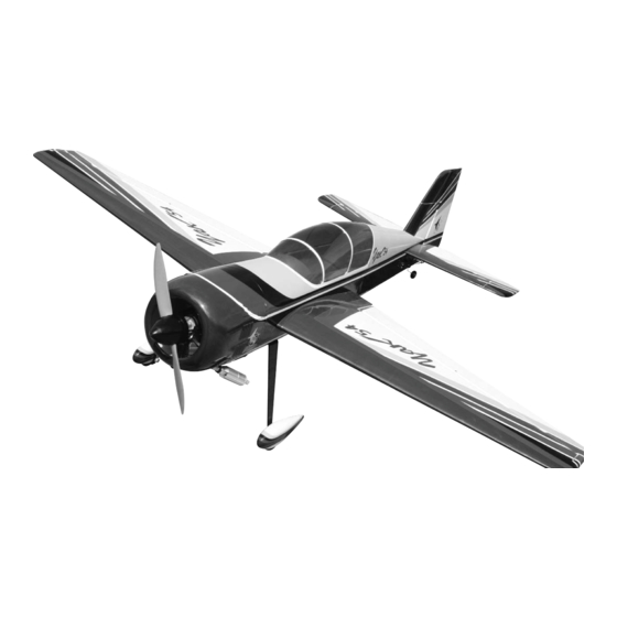
Aerobatic flying just doesn't get any better than this Yak54. The classic lines of a world class aerobatic plane
coupled with the radial cowl, add excitement to the maneuvers you love, knife edge, split S, lumcevac, torque
rolls, snaps, and ground-hugging inverted flight. What's more, we've engineered this ARF to get you into the
air with a minimum of fuss. So take a few minutes to carefully read the introductory material and then get to
work. You'll soon be out at the field with a classic aerobatic champion!
A radio-controlled model is not a toy and is not intended for persons under 16 years old. Keep
this kit out of the reach of younger children, as it contains parts that could be dangerous. A radio-
controlled model is capable of causing serious bodily injury and property damage. It is the buyer's
responsibility to assemble this aircraft correctly and to properly install the motor, radio, and all other
equipment. Test and fly the finished model only in the presence and with the assistance of another
experienced R/C flyer. The model must always be operated and flown using great care and common
sense, as well as in accordance with the Safety Code of the Academy of Model Aeronautics (5151
Memorial Drive, Muncie, IN 47302, 1-800-435-9262). We suggest you join the AMA and become prop-
erly insured prior to flying this model. Also, consult with the AMA or your local hobby dealer to find an
experienced instructor in your area. Per the Federal Communications Commission, you are required
to use only those radio frequencies specified "for Model Aircraft."
Carl Goldberg Products, Ltd. has inspected and certified the components of this aircraft. The company urges the buyer to perform
his own inspection, prior to assembly, and to immediately request a replacement of any parts he believes to be defective for their
intended use. The company warrants replacement of any such components, provided the buyer requests such replacement with-
in a period of 90 days from the date of purchase and provided the defective part is returned, if so requested by the company.
No other warranty, expressed or implied, is made by the company with respect to this kit. The buyer acknowledges and under-
stands that it is his responsibility to carefully assemble the finished flying model airplane and to fly it safely. The buyer hereby
assumes full responsibility for the risk and all liability for personal or property damage or injury arising out of the buyer's use of the
components of this kit.
CARL GOLDBERG PRODUCTS, LTD.
P.O. Box 818 Oakwood GA 30566 Phone #678-450-0085 Fax # 770-532-2163 www.carlgoldbergproducts.com
©copyright 2005 Carl Goldberg Products, Ltd.
Y
a
k
Y
a
k
WARNING
LIMITED WARRANTY
5
4
5
4
Advertisement
Table of Contents

Related Manuals for Carl Goldberg Products Yak 54


Summary of Contents for Carl Goldberg Products Yak 54
- Page 1 LIMITED WARRANTY Carl Goldberg Products, Ltd. has inspected and certified the components of this aircraft. The company urges the buyer to perform his own inspection, prior to assembly, and to immediately request a replacement of any parts he believes to be defective for their intended use.
- Page 2 Cowl Fuselage Clear canopy Left wing panel with aileron Right wing panel with aileron Stab half left Stab half right Elevator left Elevator right Motor mounts Tail wheel bracket Main gear Wheels Stab spars(aluminum tubes) Wing tube (aluminum tube) Fuel tank Rudder...
- Page 3 COVERING Before you begin assembling your Yak 54 ARF, take some The Yak 54 ARF is covered in a premium polyester film time to read through this entire instruction book. It is chosen by many of the world's top flyers for its beauty, designed to take you step-by-step through the process and toughness, and ease of application and repair.
- Page 4 ITEMS NEEDED TO COMPLETE THIS AIRCRAFT TOOLS AND SUPPLIES FOR ASSEMBLY RADIO GUIDANCE SYSTEM (4 CHANNEL MODELING OR UTILITY KNIFE MINIMUM REQUIRED WITH 8 SERVOS) WORK SURFACE (24" X70") 12” AILERON SERVO EXTENSION WIRES ELECTRIC DRILL 24” ELEVATOR SERVO EXTENSION WIRES 1/16”, 3/32”,1/8", 3/16”, 5/32”, 1/4”, 5/64”...
-
Page 5: Wing Assembly
WING ASSEMBLY AILERON INSTALLATION AILERON SERVO INSTALLATION Note: The following pictures may not exactly match the hardware you are using. Always check the radio manufacturer's instructions when installing radio equipment. Collect the following parts: (1) Left wing (1) Right wing (1) Left aileron (1) Right aileron (10) pin hinges... - Page 6 AILERON CONTROL HORN INSTALLATION Collect the following items Thread on to one end of a 4-40 x 4” pushrod (4) Nylon clevis assemblies a nut and clevis. (4) nylon ball nuts (4) 6-32 x 3” Bolt Mount the pushrod onto the nylon clevis (4) nylon washers assemble on the aileron.
- Page 7 Tail Construction. Collect the following items (1) Stab (1) Fuselage (1) Stab halves (6) pin style hinges (4) 4-40 x 1/2” bolts (2) aluminum stab tube (2) 6-32 x 3” bolts (control horns) (2) nylon ball washers (2) nylon ball nuts (2) nylon clevis assemblies Install the control horns on the elevators in the same manner as you did the ailerons.
-
Page 8: Rudder Installation
Install the other two hinges. Trial fit the eleva- Trial fit the rudder in place making sure the tors in place making sure they will fit tightly hinge line is tight against the fin. When satis- against the trailing edge of the stab and work fied with the fit glue the hinges in place using smoothly. - Page 9 Block the tail of the plane up so that the fuse- lage is sitting level. Put the wheel inside the pant and slide both on the axel together. While holding the wheel pant level, mark the Install each axel using the locking nut. Be location of the mounting bolt by using a 1/8”...
- Page 10 Reinstall the wheel and wheel pant and retain with the other 4mm wheel collar. Align the wheel pant on the gear leg with the hole you drilled for the blind nut. Install the 4-40 x 1/2” socket head screw. Don’t forget to use locktite to make sure it does not come loose.
-
Page 11: Elevator Servos
Elevator Servos Collect the following parts: (2) 4-40 x 2-3/4” threaded pushrods (2) metal clevis (2) 4-40 nuts (2) clevis retainers Thread the 2-3/4” pushrod into the clevis assembly on the rudder horn. Install the nut and metal clevis on the other end and attach to servo. -
Page 12: Rudder Servo
Rudder Servo 1. * Collect the following parts: (2) braided steel cable (2) metal clevis (2) 4-40 nuts (2) clevis retainers (4) threaded cable couplers (4) cable swages 2. Epoxy the rear bulkhead in place with the notch on the bottom fitting over the receiver tray and flush against the bulkhead. - Page 13 rudder cable access hole Thread the cable into the access hole in the side of the fuselage. Repeat for the other cable. Thread the cable through one of the swages then through the hole in the end of the thread- ed coupler and back through the swage.
-
Page 14: Engine Installation
Draw a line across the firewall in the center. Draw a line down the firewall offset 3/16” to the left side of the plane. The 3/16” will compen- sate for the 2 degrees of right thrust built into the firewall. Note: The firewall will have a 1“ hole in the center not shown on the photo. -
Page 15: Throttle Servo
Bolt the engine in place being sure to use lock- tite on all the screws. Drill a 9/64” hole in line with the throttle output With the motor on the mounts, center the arm on your engine and insert the nylon tube for the mounts on the two line you drew on the fire- throttle pushrod. - Page 16 The throttle servo mount can now be mounted in a position to match your engine. Locate the e-z pushrod connector and install on your servo arm. Assemble the throttle servo mount by gluing the 3/8” square rails in the corners of the 1/8” plate and gluing the triangle gussets under the rails.
- Page 17 Fuel Tank Collect the following items (1) fuel tank (1) rubber tank stopper (1) clunk (1) 3mm x 25mm screw (1) cap washer large (1) cap washer small (2) 3mm x 40mm brass tube (1) 3mm x 60mm brass tube Install the 4mm silicone tube to the short brass tube and install the clunk to the other end of the silicone tube.
-
Page 18: Cowl Mounting
Cut two pieces of scrap paper about 1”: wide and 6” long and tape to the side of the fuselage so the end of the paper is over the mounting hole for the cowl. Mark the location of the holes in the paper. tank support Install the tank with the cap in the hole in the firewall. - Page 19 When mounting the cowl for flight, use locktite on all the bolts. Remove the cowl and mount the muffler on the engine. Use another piece of paper and cut to fit around the muffler. Mark the location of the paper on the fuselage so you can relocate it after the cowl is reinstall..
- Page 20 Canopy and Hatch Mounting mounting screw Fit the hatch in place with the dowels in front Collect the following items: and the tabs in the rear. (1)Hatch (1)Canopy Use the two 4-40 screws through the side of (2)4-40 screws the fuselage to hold in place.
- Page 21 Install pilot and cockpit detail if desired (not Balance and Control Throws included). Glue the canopy in place using Zap canopy CG Balancing glue. Do not glue the canopy in place without the hatch cover mounted on fuselage and screwed in place. It is easy to distort the hatch Balancing the Yak is very important, you and it will not fit properly if not mounted while might need to use weight depending on...
Need help?
Do you have a question about the Yak 54 and is the answer not in the manual?
Questions and answers