Table of Contents
Advertisement
Quick Links
Advertisement
Chapters
Table of Contents

Related Manuals for Koden KGP-920


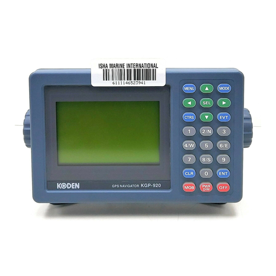
Summary of Contents for Koden KGP-920
- Page 2 No part of this publication may be reproduced, transmitted, translated in any form by any means without the written permission of Koden Electronics Co., Ltd. The technical descriptions contained in this publication are subject to change without notice. Koden assumes no responsibility for any errors, incidentals or consequential damages caused by misinterpretation of the descriptions contained in this publication.
- Page 3 KGP-920 Preface Safety Precautions Disconnect Main Power It is still possible to receive an electric shock caused by unintentionally switching on the power during repair work. To prevent this from happening, make sure to completely disconnect the unit from the ship’s main supply before attempting any inspection and repair.
- Page 4 Preface KGP-920 Symbols used in this manual The following symbols are used in this manual. You are requested to be fully aware of the meaning of each symbol before carrying out inspection and maintenance of this equipment. Alarm mark To handle the equipment ignoring this sign may lead to injury to the human body or damage to the equipment.
-
Page 5: About Gps
Preface How to use this manual Scope of this manual This manual contains information about installation, operation and maintenance of the KGP-920 GPS navigator. Structure of this manual This manual is divided into sections according to the contents as described below. This arrangement will help you overview the whole contents as well as refer to detailed information for your specific requirement. - Page 6 Preface KGP-920 Chapter 5 : Basic Operations The name and function of each part Power On/Off Adjusting display contrast and brightness Selecting the screen String present position (EVENT) Using MOB (Man over-board) Recalling event or MOB position Displaying average speed, average bearing and elapsed time...
- Page 7 KGP-920 Preface Trouble shooting Chapter 11: Technical Reference Digital interface (IEC 61162-1 second edition) Chapter 12: Communication with external navigation system Changing to the EXTERNAL mode Route data transfer Annex Local Geodetic Systems Decca zone 0093121662-06...
- Page 8 KGP-920 Chapter 1 General information Chapter 1 General Information Page No. About GPS....................1-1 1.1.1 General ......................1-1 1.1.2 Positioning by GPS ..................1-1 1.1.3 Time required for position fix................. 1-1 Outline of the equipment.................1-2 Equipment composition ................1-2 Software type name .................1-2...
-
Page 9: Positioning By Gps
KGP-920 Chapter 1 General Information Chapter 1 General Information 1.1 About GPS 1.1.1 General GPS is a navigation system using 24 satellites (21 plus 3 in service) orbiting 20,183 km high from the earth every 11 hours 58 minutes. 1.1.2 Positioning by GPS Your position is determined by calculating the distance from two satellites (in 2-dimensional positioning) or three satellites (in 3-dimensional positioning) to your position. -
Page 10: Outline Of The Equipment
KGP-920 General Information 1.2 Outline of the equipment The KGP-920 of GPS navigator is designed and manufactured to meet the carriage requirement of the latest IMO/SOLAS regulation and its harmonized IMO resolution MSC.112(73) and IEC technical standards, shown below. IEC 60945 4 Edition 2002-08, General IEC 61108-1 Ed.2.0 2003-07: Ship borne GPS-Receiver... -
Page 11: General Information
JB-10 or 12 is required Power DC Power cable Marine radar rectifier MDC-700series PS-003A MDC-1000series MDC-1500series MDL-1100series 10.8 - 31.2VDC Chart plotter Marine radar AC Power cable Echo sounder VV-2D8-3M Auto pilot (Option) (Other brand) 100/115VAC 200/230VAC Figure 1.1 equipment composition of KGP-920 93121662-02... - Page 12 KGP-920 Chapter 2 Equipment Composition Chapter 2 Equipment Composition Page No. Standard equipment list ................2-1 Option items list..................2-1 93121662-00 Contents...
- Page 13 KGP-920 Chapter 2 Equipment composition Chapter 2 Equipment composition 2.1 Standard equipment list Item Type name Remarks Q’ty Weight/Length Display unit KGP-920.MU With vinyl cover 0.86 kg 0.62kg GA-08-KODEN Connected to GA-08, other end BNC connector 0.81kg Antenna unit GA-08L-KODEN 0.26kg...
- Page 14 Chapter 2 KGP-920 Equipment composition 8DSFA cable with N-J connector and CW-394-60M KIT Antenna cable extension kit other end plain, N-J connector, N-BNC connector* and CW-826-0.5M CW-826-0.5M A BNC connector / N-P connector 0.5m Conversion cable Receiver PCB, connector, harness...
-
Page 15: Table Of Contents
KGP-920 Chapter 3 Specifications Chapter 3 Specifications Page No. GPS receiver ....................3-1 Display section ..................3-1 Data Input/Output..................3-1 Power requirements ................3-2 Compass safe distance ................3-2 Environmental conditions ...............3-2 External dimensions and weight ............3-2 93121662-00 Contents... -
Page 16: Chapter 3 Specifications
KGP-920 Chapter 3 Specifications Chapter 3 Specifications 3.1 GPS receiver Receiving frequency 1575.42 MHz 18 channel parallel Receiving channel Receiving code C/A code Sensitivity Better than –130 dBm (elevation angle: 5 or over) Accuracy Position 10 m 2drms(GPS), 5 m 2drms(DGPS), 8 m 2drms(SBAS) 0.1 kt rms... -
Page 17: Power Requirements
Chapter 3 KGP-920 Specifications 3.4 Power requirements Input voltage: 10.8 - 31.2 VDC Power consumption: Less than 4.5 W (at 24VDC) AC Operation: AC/DC rectifier PS-003A is required. Input voltage range: 115 VAC or 230 VAC 3.5 Compass safe distance Standard: 0.8m... - Page 18 KGP-920 Chapter 3 Specifications Unit: mm (inch) Figure 3.1 The Exterior of KGP-920 with dimensions Unit: mm (inch) Figure 3.2 Service space required for KGP-920 93121662-02...
- Page 19 Chapter 3 KGP-920 Specifications GA-08: with cable (10m) GA-08L: with cable (15m) GA-08S: with cable (0.5m, for extension ) Unit: mm Weight Without cable : 0.19kg GA-08: 0.62kg GA-08L: 0.81kg GA-08S: 0.26kg Figure 3.3 The Exterior of antenna unit with dimensions...
- Page 20 4.6.1 Selecting the best site of GPS / Beacon antenna......... 4-4 4.6.2 Fixing the antenna unit ................... 4-5 4.6.3 Extension of an antenna cable............... 4-5 4.6.4 Waterproofing on the connector jointing section ........4-6 Cable connections to the KGP-920 ............4-7 Connector pin outs ..................4-9 Inspection after installation ..............4-10 93121662-00...
-
Page 21: Chapter 4 Installation
Chapter 4 Installation 4.1 Installation consideration General Qualified service technicians should perform the installation of the KGP-920 series that comprises the following operations. (1) Unpacking each component of the system. (2) Inspection of the exterior of each component unit and accessory. - Page 22 Chapter 4 KGP-920 Installation Figure 4.1 Fitting detail of KGP-920 in table mounting mode Figure 4.2 Service space required for KGP-920 0093121662-08...
-
Page 23: Flush Mounting
(4) Put the display on the opening and fix with four (4) tapping screws. In case you use M4 screws to fix the display, select an appropriate screw length that best suits fixing the unit to the panel thickness. Figure 4.3 Fitting KGP-920 in flush mounting mode 0093121662-08... -
Page 24: Antenna Unit Installation
Chapter 4 KGP-920 Installation 4.6 Antenna unit installation 4.6.1 Selecting the best site of GPS / Beacon antenna Make sure to install the antenna unit at a location where nothing shades the antenna of a view above the horizon. Objects placed above the antenna unit or too close to the antenna unit may cause signal to noise ratio to degrade and shorten measuring time. -
Page 25: Fixing The Antenna Unit
KGP-920 Chapter 4 Installation 4.6.2 Fixing the GPS antenna unit (Case1) (Case2) Antenna unit Antenna unit GA-08 GA-08 GA-08L GA-08L GA-08S GA-08S Hose clamp (Option) Screw (1”-14UNS-2B) Antenna Mast (pole) extension pole (not supplied) (not supplied) 4.6.3 Extension of an antenna cable Although the standard length of an antenna cable is 10m or 15m, extension of 30m or 60m is possible by the antenna and extension cable of an option. -
Page 26: Waterproofing On The Connector Jointing Section
Chapter 4 KGP-920 Installation 4.6.4 Waterproofing on the connector jointing section Wind the self-fusible tape around the jointing section. Pull the tape end to stretch its length to be doubled and wind it overlaid by half to 3 plies. When winding is completed, apply gentle pressure over the surface with fingers to expedite the fusion. -
Page 27: Cable Connections To The Kgp-920
KGP-920 Chapter 4 Installation 4.7 Cable connections to KGP-920 4.7.1 Single connection Antenna unit Antenna unit Whip antenna GA-08-KODEN(10m) GA-08S-KODEN RA-14 GA-08L-KODEN(15m) (0.5m) (Option) Beacon antenna coupler / unit (Option) CW-391-1-5M/10M DGPS (Option) beacon receiver Chart plotter Marine radar CW-391-1-5M/10M... - Page 28 Chapter 4 KGP-920 Installation 4.7.2 Multi connections Antenna unit Antenna unit Whip antenna GA-08-KODEN(10m) GA-08S-KODEN RA-14 GA-08L-KODEN(15m) (0.5m) (Option) Beacon antenna coupler / unit (Option) CW-391-1-5M/10M DGPS beacon receiver (Option) Chart plotter Marine radar CW-391-1-5M/10M Echo sounder (Option) Auto pilot...
-
Page 29: Connector Pin Outs
KGP-920 Chapter 4 Installation 4.8 Connector pin outs POWER DATA DATA 2 1: GND/SHILD 1: DC + 1: GND/SHILD 2: TXD (+) 2: F.GND 2: TXD (+) 3: TXD (-) 3: DC - 3: TXD (-) 4: RXD (+) 4: RXD (+) -
Page 30: Inspection After Installation
Chapter 4 KGP-920 Installation (DATA port) This port is general data output port. Output data is selected by the menu among the output of IEC 61162-1,NMEA Ver.1.5, CIF, and SHIPMATE. Output signal level is RS-422. (DATA 2 port) When CW-376/391 are used. - Page 31 KGP-920 Chapter 5 Basic Operation Chapter 5 Basic Operation Page No. The name and function of each part ............5-1 5.1.1 Control panel ....................5-1 Power On/Off....................5-2 Adjusting display contrast and brightness ...........5-2 Selecting the screen ................5-3 5.4.1 A (NAV1) screen....................5-3 5.4.2 B (NAV2) screen....................
-
Page 32: Chapter 5 Basic Operation
KGP-920 Chapter 5 Basic Operation Chapter 5 Basic Operation 5.1 The name and function of each part 5.1.1 Control panel Cursor shift (Up) Selects NAV1 , NAV2, NAV3 Recalls the menu or PLOT screen. Selects parameters Cursor shift (Left) Cursor shift (Right) -
Page 33: Power On/Off
Chapter 5 KGP-920 Basic Operation 5.2 Power On/Off Press to power on. Initial message during power-on. The receiver is performing the self-check. Message to indicate checking of GPS receiver and display has been completed. Blinking Blinks when NAVIGATOR is searching GPS satellites. -
Page 34: Selecting The Screen
KGP-920 Chapter 5 Basic Operation 5.4 Selecting the screen A (NAV1) screen: Indicates your present position as numerical data. B (NAV2) screen: Displays a bearing circle (with your boat positioned at the graph center). It shows the bearing, course, deviation, distance and cross track error from the waypoint. -
Page 35: B (Nav2) Screen
Chapter 5 KGP-920 Basic Operation (Page 3) Blinks when your position has failed to fix (Velocity made good) Position (Course made good) Elapsed time (Page 4) Your present position • LAT/LONG is displayed, when displaying position data in Loran C, Loran A or Decca LOPs mode. -
Page 36: C (Nav3) Screen
KGP-920 Chapter 5 Basic Operation 5.4.3 C (NAV3) screen : 3-D Highway mode Page number Speed Course Position Blinks when your position has failed to fix Your boat NAV3 screen shows a 3-dimensional view indicating the distance, course, cross track error, and deviation from the waypoint. - Page 37 Chapter 5 KGP-920 Basic Operation (Page 4) Close-up of PLOT screen 93121662-00...
-
Page 38: Manual
KGP-920 Chapter 5 Basic Operation 5.5 Storing present position (EVENT) You can store up to 199 present positions with numbers 001 to 199. When you store additional positions, the oldest position is deleted and the newest position is stored in its place. -
Page 39: Using Mob (Man Over-Board) Key
Chapter 5 KGP-920 Basic Operation Symbol list New symbol 5.6 Using MOB (Man over-board) key MOB function is provided for an emergency situation (if a person falls into the water) to make it easier to return to MOB point. CAUTION... -
Page 40: Recalling Event Or Mob Position
KGP-920 Chapter 5 Basic Operation (Page 2) Press [SEL] key when changing a page. Antenna height Present Date (Month, Day, Year) Present time (Greenwich or local time) The elapsed time (mm:ss) after you pressed MOB key NOTE: The time display that is shown when the elapsed time has exceeded 99 minutes 59 seconds after the MOB key was pressed. -
Page 41: Displaying Average Speed, Average Bearing And Elapsed Time
Chapter 5 KGP-920 Basic Operation LAT/LONG mode (Example) Storage number Data displayed when you press MOB key Symbol (O:Fixed), storage date, storage time Storage position Data displayed when you press EVT key Symbol, storage date, storage time Storage position 5.8 Displaying average speed, average bearing and elapsed time (1) Press [MODE] key until A (NAV1) screen appears. - Page 42 KGP-920 Chapter 6 Various Navigation Chapter 6 Various Navigation Page No. Storing waypoint (LAT/LONG) data ............6-1 6.1.1 Storing a new position or updating an existing one ........6-1 6.1.2 Writing comment ..................... 6-1 6.1.3 Copying a position ..................6-2 6.1.4 Changing comment I.D................... 6-3 6.1.5 Erasing a single waypoint ................
- Page 43 Chapter 6 KGP-920 Various Navigation 6.5.9 D (PLOT) screen during route navigation........... 6-17 Setting an anchor position ..............6-18 6.6.1 String an anchor position................6-18 6.6.2 Recalling anchor position ................6-18 6.6.3 Removing the anchor position symbol on PLOT screen ......6-19 6.6.4 Reentering an anchor position ..............
-
Page 44: Storing A New Position Or Updating An Existing One
KGP-920 Chapter 6 Various Navigation Chapter 6 Various Navigation 6.1 Storing waypoints (LAT/LONG) data NOTE: Press to backspace the NOTE: Press to clear incorrect cursor to correct an input Input. You can reenter error. Numeric data. 6.1.1 Storing a new position or updating an existing one Up to 200 waypoints can be stored in memory. -
Page 45: Copying A Position
Chapter 6 KGP-920 Various Navigation (9) Press [ENT] key and decide of a comment. Example of symbols: : Reference point : Fishing spot : Shallow : Sunken ships : Buoy : Anchoring point or other ships : Prohibited area : Fish gathering place... -
Page 46: Changing Comment I.d
KGP-920 Chapter 6 Various Navigation 6.1.4 Changing comment I.D. You can change a comment stored in memory. (1) Press [MENU] key until Menu options 1 to 9 appears. (2) Press [1] key to select “1:WAYPOINT”. (3) Enter storage number (001 to 399) using numeric keys. -
Page 47: Setup Of Waypoint Navigation
Chapter 6 KGP-920 Various Navigation 6.2 Setup of waypoint navigation NOTE: Press to backspace the NOTE: Press to clear incorrect cursor to correct an input Input. You can reenter error. Numeric data. 6.2.1 Setting waypoint navigation The position data for each waypoint must be set prior to navigating to waypoints. You can use the data already stored from Menu, or you can set the waypoints on A (NAV1), B (NAV2), C (NAV3) or D (PLOT) screen (called the quick waypoint navigation). -
Page 48: Reentering The Starting Point In Waypoint Navigation
KGP-920 Chapter 6 Various Navigation 6.2.3 Reentering the starting point in waypoint navigation Once reset, the present position is used as the new point of origin for waypoint navigation. While the 1st to 4th pages of either the A (NAV 1), B (NAV 2), C (NAV 3) or D (PLOT), are displayed. -
Page 49: C (Nav3) Screen During Waypoint Navigation
Chapter 6 KGP-920 Various Navigation 6.2.6 C (NAV3) screen during waypoint navigation NOTE: To change a display page: Press this key WPT number Page number Page number Speed Cross track error Course Deviation angle Present position WPT position XTE alarm range... -
Page 50: Cross Track Error And Course Deviation Angle
KGP-920 Chapter 6 Various Navigation 6.3 Cross track error and course deviation angle 6.3.1 Navigation graph of (NAV2) screen Use the navigation graph to check the distance and bearing to the waypoint. When the distance to WPT is further than the range (radius) of navigation graph, the WPT locates on the circle of navigation graph. -
Page 51: Electronic Fairway (Nav3) Screen
Chapter 6 KGP-920 Various Navigation 6.3.2 Electronic fairway (NAV3) screen Use the three-dimensional chart for navigation on the course line. You can set a course width from Menu (6: Alarm). Symbol “ ” shows the waypoint, and your ship and track are shown along the course line. - Page 52 KGP-920 Chapter 6 Various Navigation ( Nearing to the WPT ) When you close to the waypoint, the course line length decreases to 4 (nm, sm, km), 2 (nm, sm, km) and 1 (nm, sm, km). Then, the WPT marking closes to your ship.
-
Page 53: Storing And Erasing Routes
Chapter 6 KGP-920 Various Navigation 6.4 Storing and erasing routes NOTE: Press to backspace the NOTE: Press to clear incorrect cursor to correct an input Input. You can reenter error. Numeric data. 6.4.1 Storing your route • Up to 20routes and 230 waypoints can be registered for one route. -
Page 54: Automatic Switching Of Waypoints
KGP-920 Chapter 6 Various Navigation 6.4.2 Automatic switching of waypoints Route navigation can switch the current waypoint in two ways: switching in CIRCLE mode and switching in BI-SECTOR mode. In CIRCLE mode, the next waypoint is shown when you reach the proximity alarm circle. -
Page 55: Erasing A Single Route
Chapter 6 KGP-920 Various Navigation 6.4.4 Erasing a single route (1) Press [MENU] key until Menu options 1 to 9 appears. (2) Press [2] key to select “2:ROUTE”. (3) Press [1] key to select “1: RTE EDIT”. Route Input screen is displayed. -
Page 56: Route Setup
KGP-920 Chapter 6 Various Navigation 6.5 Route setup You can use up to 400 points (maximum) to go to a final destination using route navigation. You can also reverse the navigation route to return to the start point. To do so, you must first store the waypoints and route from Menu (using option 2). - Page 57 Chapter 6 KGP-920 Various Navigation 6.5.3 Checking a route point position You can check the waypoints on a route from the Menu. (1) Press [MENU] key until Menu options 1 to 9 appears. (2) Press [2] key to select “2:ROUTE”.
- Page 58 KGP-920 Chapter 6 Various Navigation 6.5.6 Switching between distance and time to go When you select the “DIST” (Distance to WPT) or “TDIST” (Total distance) on NAV1, NAV2 or NAV3 screen in route navigation, the respective “TTG” (Time to go to WPT) or “T.TTG” (Total time to go) is shown.
-
Page 59: B (Nav2) Screen During Route Navigation
Chapter 6 KGP-920 Various Navigation 6.5.7 B (NAV2) screen during route navigation NOTE: To change a display page: NOTE: Positioning has failed or the distance Press this key has exceeded 9999 nm, sm or km. DST: 9999 Forward (→) or backward (←) navigation... -
Page 60: D (Plot) Screen During Route Navigation
KGP-920 Chapter 6 Various Navigation 6.5.9 D (PLOT) screen during route navigation Page number NOTE: To change a display page: Distance to the next Press this key Route point Bearing to the next Point (Total distance Can also be shown) -
Page 61: Setting An Anchor Position
Chapter 6 KGP-920 Various Navigation 6.6 Setting an anchor position After arriving at your destination, it is possible to drift from the anchor position due to a tide or wind. Once the anchor position is stored in memory, it is easy to check the distance and bearing moved from the anchor position. -
Page 62: Removing The Anchor Position Symbol On Plot Screen
KGP-920 Chapter 6 Various Navigation 6.6.3 Removing the anchor position symbol on PLOT screen You can remove the anchor position as a symbol on the PLOT screen. (1) Press [MODE] key until D (PLOT) screen appears. (2) Press [SEL] key until page 6 screen appears. -
Page 63: B (Nav2) Screen During Anchor Position Setup
Chapter 6 KGP-920 Various Navigation 6.6.6 B (NAV2) screen during anchor position setup Page number Page number Distance from Time to go from present position to present position to anchor position anchor position Bearing from Arrival time present position to... -
Page 64: Track Display
KGP-920 Chapter 6 Various Navigation 6.7 Track display You can display track, the waypoint, course line, and cross cursor on the PLOT screen. 6.7.1 Display a cross cursor on PLOT screen You can display a cross cursor and position it on the screen. -
Page 65: Scaling The Plot Screen
Chapter 6 KGP-920 Various Navigation 6.7.3 Scaling the PLOT screen Initial scale: 0.025 You can select a display scale of PLOT (pages: 1, 2, 4) screen. (1) Press to [ ] or [ ] key to select a desired range. - Page 66 KGP-920 Chapter 6 Various Navigation (Adjusting the track recording interval) To adjust the track recording interval (time or distance interval), locate cursor on PLOT option, and press ENT key. You can set the unit of track distance interval from the Menu 2: UNIT (DST) of 8 INITIAL.
- Page 67 KGP-920 Chapter 7 Alarms Chapter 7 Alarms Page No. Kinds of alarms..................7-1 7.1.1 Anchor watch alarm (ANCW)................7-1 7.1.2 Proximity alarm (PROX) .................. 7-1 7.1.3 Cross track error alarm (XTE) ................ 7-2 7.1.4 Course deviation angle alarm (CDI)............... 7-2 Alarm explanation..................7-2 Setting and canceling................7-3...
-
Page 68: Chapter 7 Alarms
KGP-920 Chapter 7 Alarms Chapter 7 Alarms 7.1 Kinds of alarms There are four kinds of alarms, anchor watch (ANCW), proximity (PROX), cross track error (XTE) and course deviation angle. 7.1.1 Anchor watch alarm (ANCW) An anchor watch alarm can alert you if your boat drifts a set distance from where it is activated. This alarm function will not work if the alarm range is set to "0.00". -
Page 69: Cross Track Error Alarm (Xte)
Chapter 7 KGP-920 Alarms 7.1.3 Cross track error alarm (XTE) The cross track error (XTE) alarm alerts you when you have deviated from your course line by a predetermined distance. The alarm function does not work if the alarm range is set to '0.00'. The course width shown on NAV3 screen is the same as the XTE alarm value you have set. -
Page 70: Setting And Canceling
KGP-920 Chapter 7 Alarms 7.3 Setting and canceling (Setting alarm) (1) Press [MENU] key until Menu options 1 to 9 appears. (2) Press [6] key to select “6:ALARM”. (3) Select item number of the alarm to be set from the numerical keypad. - Page 71 KGP-920 Chapter 8 Setup Procedure Chapter 8 Setup Procedure Page No. Menu options ...................8-1 Menu 3: GPS.....................8-2 8.2.1 Monitoring GPS satellite signal reception ............ 8-2 8.2.2 Selecting a measuring system mode ............8-2 8.2.3 Selecting a geodetic datum ................8-2 8.2.4 Setting antenna height (above sea level) ............
- Page 72 Chapter 8 KGP-920 Setup Procedure 8.5.4 Changing sail mode ..................8-16 8.5.5 Displaying position data in LAT/LONG mode..........8-16 8.5.6 Changing the latitude and longitudinal display digits....... 8-16 8.5.7 Specifying the chain and secondary stations for Loran C, Loran A or Decca .........................
-
Page 73: Setup Procedure
KGP-920 Chapter 8 Setup Procedure Chapter 8 Setup Procedure 8.1 Menu options NOTE : You can select an option from Menu in two ways: by direct numeric key entry and by cursor shifting. This manual explains how to enter numeric values for easy understanding, but you can also use the cursor for option selection. -
Page 74: Menu 3: Gps
Chapter 8 KGP-920 Setup Procedure 8.2 Menu 3: GPS 8.2.1 Monitoring GPS satellite signal reception You can monitor the signal status from GPS (SBAS) satellites. The signals from 3 satellites are used for two-dimensional positioning, but signals from 4 or more satellites are required for three-dimensional positioning. -
Page 75: Setting Antenna Height (Above Sea Level)
KGP-920 Chapter 8 Setup Procedure Cursor 8.2.4 Setting antenna height (above sea level) Initial height: 0 In case of 2D mode, the antenna height from sea level must be entered within 5 meters or 16 3/8 feet in accuracy. If failed, the positioning accuracy may be worsened. The data can be set in either metric or imperial system. -
Page 76: Setting Raim Function
Chapter 8 KGP-920 Setup Procedure 8.2.7 Setting RAIM function Initial setup: ON RAIM (Receiver Autonomous Integrity Monitoring) is the function, which supervises whether GPS holds the accuracy, which the user chose (100m or 10m). If this function is turned ON, the bar of RAIM accuracy will be displayed. -
Page 77: Menu 4: Differential Gps (Dgps)
KGP-920 Chapter 8 Setup Procedure 8.3 Menu 4: Differential GPS (DGPS) This DGPS system can improve the GPS positioning accuracy. There are two styles, BEACON and SBAS, in DGPS, and BEACON is further divided into the system of internal receiver and external receiver. -
Page 78: Setting A Dgps Timeout
Chapter 8 KGP-920 Setup Procedure (3) Press [2] key to select “2:DGPS MODE”. (4) Press [ ] or [ ] key to move cursor onto ”AUTO”, “ON” or “OFF”. (5) Press [ENT] key. Cursor 8.3.4 Setting a DGPS timeout Initial setup: 40 sec If the correction data from beacon receiver is interrupted or has errors, NAVIGATOR holds the last differential correction for the duration of timeout. - Page 79 KGP-920 Chapter 8 Setup Procedure (Selecting a station in the manual mode) Internal beacon receiver system In the manual mode of internal beacon receiver system, specify the station number between 001 and 480. (Refer “Table of DGPS reference stations” of supplement.) (1) Press [MENU] key until Menu options 1 to 9 appears.
-
Page 80: String A Beacon Station (Internal Beacon Receiver System Only)
Chapter 8 KGP-920 Setup Procedure Cursor Cursor (9) Press [2] key to select “2:FREQUENCY”. (10) Specify receiving frequency (4-digit) of beacon station using numeric keys (0 to 9). (11) Press [ENT] key to set receiving frequency. (12) Press [ ] key to move cursor onto bit rate. -
Page 81: Selecting The Dgps Input Signal Baud Rate
KGP-920 Chapter 8 Setup Procedure (17) Press [ ] or [ ] key to set bit rate. (18) Press [ENT] key . Bit rate (19) Press [ ] key to move cursor to the station name (STN NAME) field. (20) Press [ ] key to select a comment letter or symbol from the comment letter table by locating cursor on it, or enter a value using numeric keys. -
Page 82: Message Monitor (Beacon Dgps Only)
Chapter 8 KGP-920 Setup Procedure (4) Press [5] key to select “5:DGPS MONITOR”. Cursor Displays Frequency being received, bit rate, S/N ratio and ID No (beacon station number) Display age of DGPS data HEALTH indicates health status of reference station. -
Page 83: Menu 5: Compensation
KGP-920 Chapter 8 Setup Procedure 8.4 Menu 5: Compensation 8.4.1 Correcting your position You can compensate your GPS present position given by GPS in the following two ways: • Enter the latitude and longitude of your actual position using numeric keys. -
Page 84: Checking The Correction Offset
Chapter 8 KGP-920 Setup Procedure (5) Enter the latitude/longitude correction offset. Example: The correction offset “S0 0.193 / W0 0.148” is entered by pressing the following keys in exact order given below. [0],[0],[0],[0],[1],[9],[3],[S],[ENT],[ ],[0],[0],[0],[0],[0],[1],[4],[8],[W],[ENT] NOTE: Press to clear incorrect Input. You can reenter Numeric data. -
Page 85: Displaying Local Time
KGP-920 Chapter 8 Setup Procedure (1) Press [MENU] key until Menu options 1 to 9 appears. (2) Press [5] key to select “5:COMP.”. (3) Press [3] key to select “3:MAG.V”. (4) Press [ ] or [ ] key to move cursor onto “AUTO” . - Page 86 Chapter 8 KGP-920 Setup Procedure NOTE: Press to clear incorrect input. You can reenter a “+” or “-“ sign and numeric data. International date line Greenwich Mean International date line Time (GMT) +12 -12 +12 -12 -11 -10 -9 -5 -4...
-
Page 87: Menu 8: Initial Setting
KGP-920 Chapter 8 Setup Procedure 8.5 Menu 8: Initial setting 8.5.1 Setting average constants(measuring position, speed and course) Initial setup: HIGH Use the averaging function to compare GPS sensor signals several times and get their average. This stabilizes the GPS position (latitude and longitude), speed and course data. The maximum averaging rate is “LOW”... -
Page 88: Changing Sail Mode
Chapter 8 KGP-920 Setup Procedure 8.5.4 Changing sail mode Initial setup: GREAT CIRCLE You can change the navigation mode. There are two navigation modes. Great Circle course: ..The shortest course on a sphere. Rhumb Line course: ..Straight course on a Mercator chart. -
Page 89: Menu 9: Interface
KGP-920 Chapter 8 Setup Procedure 8.6 Menu 9: Interface 8.6.1 Selecting an output data format of DATA port . Initial setup: IEC DATA port You can select the format of output data. (1) Press [MENU] key until Menu options 1 to 9 appears. -
Page 90: Explanation Of Output Data (Sentence)
Chapter 8 KGP-920 Setup Procedure 8.6.3 Explanation of output data (sentence) Waypoint Arrival Alarm Autopilot Sentence "B" (Bearing from origin or present position to the waypoint) Bearing - Point of Origin to Destination Bearing & Distance to Waypoint in Great Circuit navigation... -
Page 91: Selecting An Output Data Format Of Data2 Port
KGP-920 Chapter 8 Setup Procedure 8.6.5 Selecting an output data format of DATA 2 port . Initial setup: Extension data port You can select either the extension data port or exclusive port of ACK/ALR for DATA 2 port. It can select ACK/ALR of a menu3 in turning on or turning off. If ACK/ALR is turned ON, it will be set to exclusive port of ACK/ALR, and it will be set to extension data port if it turns OFF. -
Page 92: Initialization
Chapter 8 KGP-920 Setup Procedure 8.7 Initialization (Displaying the menu) Turn power on, then press the ENT key while the screen message "CHECK OK" is displayed. (How to use menus) Initialization 1) Press [1] key to select “1:INITIALIZE”. 2) Press [ENT] key. Menu is initialized and the screen for powering off will appear. -
Page 93: Selecting An Initial Value (North, South, East, West) Of Latitude/Longitude
KGP-920 Chapter 8 Setup Procedure MANUAL: Press the EVT key, then specify desired registration numbers (in the range of 001 to 199) from the numerical keypad. In the MANUAL mode, you can specify desired registration numbers 8.7.5 Selecting an initial value (North, South, East, West) of latitude/longitude Initial setup: N/W N/W (N. - Page 94 KGP-920 Chapter 9 How to use LOPs Chapter 9 How to use LOPs Page No. Initial setup for LOPs display ..............9-1 9.1.1 Selecting LOP (Loran C, Loran A or Decca)..........9-1 9.1.2 Setting the chain and secondary stations to be displayed ......9-1 9.1.3 Registering a position in LOPs ..............
- Page 95 KGP-920 Chapter 9 How to use LOPs Chapter 9 How to use LOPs 9.1 Initial setup for LOPs display Measured longitude and latitude can be translated into loran C, loran A or decca LOPs mode. To turn on the LOPs mode, the following initial setup is required.
- Page 96 Chapter 9 KGP-920 How to use LOPs (7) Press [ ] key. (8) Press [ENT] key. (9) Press [ ] or [ ] key to select the secondary station 2. (10) Press [ENT] key. Cursor Secondary station 1 Secondary station 1...
- Page 97 KGP-920 Chapter 9 How to use LOPs 9.1.3 Registering a position in LOPs Following describes the procedure for replacing LAT/LONG display with LOP and registering a position in LOP (1) Press [MENU] key until Menu options 1 to 9 appears.
- Page 98 Chapter 9 KGP-920 How to use LOPs 9.2 Storing waypoints (LOPs data) NOTE: Press to backspace the NOTE: Press to clear incorrect cursor to correct an input Input. You can reenter error. Numeric data. 9.2.1 String a new position or updating an existing one Up to 200 waypoints can be stored in memory.
- Page 99 KGP-920 Chapter 9 How to use LOPs 9.3 Correcting your position (LOPs) You can compensate your GPS present position given by GPS in the following two ways: • Enter the LOPs of your actual position using numeric keys. • Enter the correction offset to use.
- Page 100 Chapter 9 KGP-920 How to use LOPs (5) Press [ENT] key. (6) Press [ ] key to move cursor to Loran A LOPs field of secondary station 2. (7) Enter correct (5-digit) LOPs of secondary station 2 using numeric keys.
- Page 101 KGP-920 Chapter 9 How to use LOPs 9.3.2 Entry of correction offset (Correction by Loran C LOPs data entry) When your position is displayed in Loran C LOPs mode, you can correct it by entering the Loran C LOPs correction offset.
- Page 102 Chapter 9 KGP-920 How to use LOPs (7) Press [ENT] key. (8) Press [ ] key to move cursor to correction offset field of secondary station 2. (9) Press [SEL] key to change the positive (+) or negative (-) sign of correction offset.
- Page 103 KGP-920 Chapter 9 How to use LOPs Actual position (to be entered) Present position Correction position Present position (GPS fix) Actual position (to be entered) Correction offset Secondary st. –00:20 usec Green st.1 0G:30:42 usec Secondary st.1 0G:30:42 Secondary st. +00:19 usec Purple st.2 0C:76:35 usec...
- Page 104 Chapter 9 KGP-920 How to use LOPs 9.4 Calculating LOPs based on LAT/LONG data 9.4.1 Calculating Loran C LOPs based on LAT/LONG data You can enter a Loran C chain number and the first digit of two secondary stations, NAVIGATOR calculates the Loran C LOPs based on the specified LAT/LONG data and displays the LOP values.
- Page 105 KGP-920 Chapter 9 How to use LOPs 9.4.2 Calculating Loran A LOPs based on LAT/LONG data When You enter a combination of two secondary stations of Loran A, NAVIGATOR calculates the Loran A LOPs based on the specified LAT/LONG data and displays the LOP values.
- Page 106 Chapter 9 KGP-920 How to use LOPs CAUTION Do not use the converted LOPs position data for waypoint or route navigation because of likely conversion errors. Accuracy of converted positions can be off 1/4 mile or more. 9.4.3 Calculating Decca LOPs based on LAT/LONG data When you enter a Decca chain number and a combination of two secondary stations, NAVIGATOR calculates the Decca LOPs based on the specified LAT/LONG data and displays the LOP values.
- Page 107 KGP-920 Chapter 9 How to use LOPs Data currently stored Specified data number ( “X L/L-LOP” : fixed) CAUTION Do not use the converted LOPs position data for waypoint or route navigation because of likely conversion errors. Accuracy of converted positions can be off 1/4 mile or more.
- Page 108 KGP-920 Chapter 10 Maintenance and Trouble shooting Chapter 10 Maintenance and Trouble shooting Page No. 10.1 Periodic inspection and cleaning ............10-1 10.1.1 Monthly check....................10-1 10.1.2 maintenance....................10-1 10.2 Trouble shooting..................10-1 10.2.1 Information required service ..............10-1 10.2.2 Trouble shooting ..................10-1 10.2.3 Error message .....................
- Page 109 KGP-920 Chapter 10 Maintenance and Trouble shooting Chapter 10 Maintenance and troubleshooting 10.1 Periodic inspection and cleaning 10.1.1 Monthly check Check if there is any loose connection on the Processor unit for GPS Antenna, radar or navigational unit. 10.1.2 Maintenance If the Processor unit is smeared or stained with dirt, wipe the surface of the unit with soft dry cloth.
- Page 110 Chapter 10 KGP-920 Maintenance and Trouble shooting Faults detected Possible cause of the failure Remedial action Unstable signal reception 1. Are the connections between the 1. Check the connection and GPS antenna and the display unit reconnect, if necessary. is correct and firm? 2.
- Page 111 KGP-920 Chapter 10 Maintenance and Trouble shooting 10.2.3 Error message (An error message may appear when you power on) BACKUP ERROR The backup data saved at RAM is faulty. ROM CHANGED A checksum differs from the backed-up value. ROM ERROR Communication between CPU and ROM is faulty.
- Page 112 KGP-920 Chapter 11 Technical Reference Chapter 11 Technical Reference Page No. 11.1 Digital interface (IEC 61162-1 second edition)........11-1 11.1.1 input data format (DATA 2 port)..............11-1 11.1.2 Output data format (DATA / DATA 2 port) ..........11-1 11.1.3 Output data specification................11-1 11.1.4 Output sentence ..................
-
Page 113: Technical Reference
KGP-920 Chapter 11 Technical Reference 11.1 Digital Interface (IEC 61162-1 second edition) 11.1.1 Input data format (DATA 2 port) RTCM SC104 Ver.2.0 (DGPS) 11.1.2 Output data format (DATA / DATA 2 port) Data per one byte is as follows: Parity bit: none... - Page 114 Chapter 11 KGP-920 Technical Reference Description Contents of data field GPAPB Heading / Track controller (auto pilot) sentence B $ GP APB, A, A, x.x, a, N, A, A, x.x, a, c--c, x.x, a, x.x, a, a*hh<CR><LF> Mode indicator A: Autonomous...
- Page 115 KGP-920 Chapter 11 Technical Reference Description Contents of data field GPBWC Bearing and distance to waypoint $ GP BWC, hhmmss.ss, llll.lll, a, yyyyy.yyy, a, x.x, T, x.x, M, xx, N, c--c, a*hh<CR><LF> Mode indicator A: Autonomous D: Differential M: Manual input...
- Page 116 Chapter 11 KGP-920 Technical Reference Description Contents of data field GPGBS GPS satellite fault detection $ GP GBS, hhmmss.ss, x.x, x.x, x.x, x.x, x.x, x.x, x.x *hh<CR><LF> Standard deviation of bias estimate Estimate of bias on most likely failed satellite...
- Page 117 KGP-920 Chapter 11 Technical Reference Description Contents of data field GPGLL Geographic position (latitude/longitude) $ GP GLL, lllll.lll, a, yyyyy.yyy, a, hhmmss.ss, A, a*hh <CR><LF> Longitude Latitude, Mode indicator A: Autonomous Sentence type D: Differential Talker device M: Manual input...
- Page 118 Chapter 11 KGP-920 Technical Reference Description Contents of data field GPGSV GPS Satellite in view $ GP GSV, x, x, xx, xx, xx, xxx, xx, …………., xx, xx, xxx, xx*hh <CR><LF> “2nd and 3 SNR (C/No) 00-99 dB Hz, null when not tracking...
- Page 119 KGP-920 Chapter 11 Technical Reference Description Contents of data field GPRMC Recommended minimum specific GPS data $ GP RMC, hhmmss.ss, A, lllll.lll, a, yyyyy.yyy, a, x.x, x.x, xxxxxx, x.x, a, a*hh <CR><LF> Mode indicator A: Autonomous UTC of position fix...
-
Page 120: Input / Output Circuit
Chapter 11 KGP-920 Technical Reference Description Contents of data field GPWPL Waypoint location *A maximum of four Waypoints are outputted. $ GP WPL, llll.lll, a, yyyyy.yyy, a, c--c*hh <CR><LF> Waypoint identifier Waypoint latitude, E/W Waypoint latitude, N/S Sentence type Talker device... - Page 121 KGP-920 Chapter 11 Technical Reference (DATA port output circuit) Device: Driver IC AM26C311 (T.I) +Vcc AM26C31I TXD (+) TXD (- ) (DATA 2 port input circuit) Input load: 470 / 2.4k ohm Device: Photo-coupler TLP181(Toshiba) +Vcc TLP-181 RXD (+) RXD (-) +Vcc 2.4k...
- Page 122 Chapter 11 KGP-920 Technical Reference DATA 2 port output circuit Device: Transistor 2SC2712 EXT BUZZER 2SC2712 11-10 93121662-00...
- Page 123 KGP-920 Chapter 12 Communication with external navigation system Chapter 12 Communication with external navigation system Page No. 12.1 Changing to the EXTERNAL mode............12-1 12.2 Route data transfer ................12-2 12.2.1 Complete route transfer................12-2 12.2.2 Selecting route navigation................12-3 12.2.3 Working(active) route transfer ..............12-3 12.2.4 Error message .....................
-
Page 124: Chapter 12 Communication With External Navigation System
(6) Press [ENT] key . Cursor A small E is displayed at the end of the way point identifier to show KGP-920 is in external mode. Route identifier shows maximum leading 5 characters of the original route name while waypoint identifier shows maximum leading 6 characters of the original waypoint name. -
Page 125: Route Data Transfer
When consecutive more than single routes are received. It indicates “INVALID ext. route” and voids received data but the previously loaded route data remains and valid. KGP-920 judges data transfer is ended when more than 10 second interruption of data transfer occurs. The Complete route is stored as number 19 route. -
Page 126: Selecting Route Navigation
12.2.3 Working (active) route transfer When KGP-920 receives Working route data for the first time, it shows “LOADED ext. active route” and goes into Working route mode regardless of previous navigation mode due to the first priority. As far as KGP-920 receives Working route data within 10 seconds consecutively, it continues to work for the received working route. -
Page 127: Error Message
Chapter 12 KGP-920 Communication with external navigation system DEACTIVATED Working route is finished ext. active route Following is an example of Working route data. Refer to IEC61162-1 for detail. Max. character number in a line is 124 bytes including w: Working route Max. - Page 128 KGP-920 Annex Annex Page No. Local Geodetic Systems ................... A-1 Decca zone......................A-3 93121662-00 Contents...
- Page 129 Local Geodetic Systems The number assigned to each place name is the set values used in the “Selecting a geodetic datum” (Page 8-3) In alphabetical order Name Abbreviation Name Abbreviation ALASKA / CANADA IWO JIMA ARC 50 JAPAN ARC 60 JOHNSTON ARGENTIN KELGUELEN...
- Page 130 Local Geodetic Systems Name Abbreviation Name Abbreviation SWEDEN TERN TOKYO TRINIDAD TRISTAN TUNISIA WGS-72 WGS-84 HU-TZU-SHAN...
- Page 131 Decca zone Chain Code Chain Code EUROPE NORTH WEST AUSTRALIA South Baltic Dampier Vestlandet Port Hedland Southwest British CANADA Northumbrian Anticosti Holland Newfoundland North British Cabot Straits Lofoten Nova Scotia German INDIAN OCEAN North Baltic Salaya SOUTH AFRICA Northwest Spanish Trondelag Southwest Africa English...
Need help?
Do you have a question about the KGP-920 and is the answer not in the manual?
Questions and answers