Table of Contents
Advertisement
Quick Links
Advertisement
Table of Contents

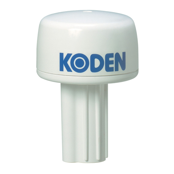
Summary of Contents for Koden GPS-20A MkII
-
Page 3: Revision History
No part of this publication may be reproduced, transmitted, translated in any form by any means without the written permission of Koden Electronics Co., Ltd. The technical descriptions contained in this publication are subject to change without notice. Koden assumes no responsibility for any errors, incidentals or consequential damages caused by misinterpretation of the descriptions contained in this publication. - Page 4 Koden is not liable for any damages caused by earthquake, lightning, wind and flood damage and fire for which Koden is not responsible, and actions by third parties, other accidents, customer’s unintended error/abuse and the use under other abnormal conditions.
-
Page 5: For Your Safe Operation
When the inside is to be checked, ensure to switch off the power and to discharge the residual voltage for safety. An engineer authorized by Koden shall carry out the inspection and maintenance works. - Page 6 In case of failure, please Warning contact Koden’s dealers or Koden. In case of smoking or firing, switch off the power in the boat and of this equipment. It may lead to firing, electric shock or damages.
-
Page 7: Table Of Contents
GPS-20A MkII Contents Contents Revision History............................ i Important Notice ..........................ii For your Safe Operation ........................iii Symbol used in this Instruction Manual ..................iii Precaution on equipment ......................iii Precaution on handling ......................... iv Contents ............................. v Introduction ............................vi System configuration ......................... -
Page 8: Introduction
/ MICHIBIKI (Quasi-Zenith Satellite System) service. By simply connecting a power supply to the GPS-20A MkII, highly accurate position data can be quickly supplied to a Plotter or the ship’s navigation devices. GPS (Global Positioning System) is a position measuring system that uses 4 satellites for each of 6 orbits (3 spare), with durations of 11 hours 58 minutes, orbiting approximately 20,000km above the earth. -
Page 9: System Configuration
GPS-20A MkII System Configuration System Configuration GPS receiver module GPS-20A MkII *denotes cable length of 10m Chart plotter B Type GTD-110/150 GTD-120 Echo sounder B Type CVS-1410 series CVS-FX1/FX2/FX2BB CVS-702D/705D/707D B Type Echo sounder CVS-126 CVS-128/128B B Type Digital sonar... -
Page 10: Configuration Of Equipment
Configration of Equipment GPS-20A MkII Configuration of Equipment Standard Equipment Configuration List Item Type name Remarks Weight Q’ty Type B 250 g Cable: CW-563-3-10M Receiver GPS-20A MkII (Cable not With 6P connector Module included) (BD-06BFFA-LL6001) fitted Installation GPS-20A MkII.IM.E English... -
Page 11: Chapter 1 Specification
RX input SBAS (WAAS, MSAS, EGNOS) QZSS (L1S) positioning 1.2 Serial data (1) Format: NMEA-0183 Ver. 2.3 (2) Input data Parameter settings: KODEN private command, 4800bps Refer to chapter 3 for details. (3) Output data Sentence: GGA, GLL, GSA, RMC, VTG, ZDA 1.3 Power supply specifications Input voltage: 10.8 to 31.2 VDC... -
Page 12: External Dimensions And Weight
13.2 Hz and 60 Hz. (3) Water resistance IPX6 standard (IEC 60945) Water resistant type (JISF8001) 1.6 External dimensions and weight Dimensional diagram: Refer to the diagram below Weight: 250g (0.55 lb) (Except cable) Unit: mm Figure 1.1 GPS-20A MkII external dimensions 0092621642-00... -
Page 13: Chapter 2 Installation
Unpack the contents and check each component against the component delivery list. If the contents differ from that which is on the list, or there are damaged components, contact the shipping agent or the nearest KODEN dealer. 2.3 Installation site Be sure to install the GPS receiver module in the highest possible location on the ship for optimum reception of the satellite signal. - Page 14 Chapter 2 Installation GPS-20A MkII Table 1 Minimum distances between support struts Object Diameter Minimum distance Support strut 10cm 1.5m Support strut 30cm 3.0m VHF whip antenna 4m (min) 4m (min) Loop antenna RX whip antenna 1m (min) INMARSAT antenna...
-
Page 15: Installation Method
GPS-20A MkII Chapter 2 Installation 2.4 Installation method The following examples show typical installation methods. Installation example 1: The pole used has no screw thread tooled. Fix the GPS20A MkII to the pole using the hose band and tighten firmly. - Page 16 Chapter 2 Installation GPS-20A MkII Installation example 3 GPS receiver module Thread: 1-14UNS-2A Thread per 25.4 mm (1 inch): 14 Pitch: 1.8143 mm Thread length: 26 mm Mounting pipe (User supply) Thread diameter: 25.4 mm Pitch diameter: 24.221 mm Connecting cable Installation precautions (1) Adhesive plastic sealant or silicone for plastic is recommended for fixing screws.
-
Page 17: Chapter 3 Technical References
GPS-20A MkII Chapter 3 Technical References Chapter 3 Technical References 3.1 Serial input/output data 3.1.1 Input data 3.1.1.1 Various settings 1: Header (HEX) X 0000 <CR><LF> 2: Setting value (ASCII code, integer) 3: End code Baud rate: 4800bps Item to set... -
Page 18: Output Sentence
Chapter 3 Technical References GPS-20A MkII 3.1.2.4 Output sentence Note: *hh: Checksum <CR>: Carriage return <LF>: Line feed GPGGA GPS Positioning Data $ GP GGA, hhmmss, xxxx.xxxx, N/S, xxxxx.xxxx, E/W, x, xx, xxx.x, 0/- xxxx, Latitude Longitude Antenna altitude UTC of position fix 0 or –... - Page 19 GPS-20A MkII Chapter 3 Technical References GPVTG Course over ground and ground speed $ GP VTG, xxx.x, T, , , xxx.x, N, xxx.x, K, a*hh <CR><LF> Mode indicator Speed over Speed over Cours over N:Invalid Ground,kt. Ground,km/h Ground true A:Auto Sentence type D:DGPS...
-
Page 20: Cable Connections And Connector Pin-Outs
Chapter 3 Technical References GPS-20A MkII 3.2 Cable connections and connector pin-outs A/B type 1. DC (-) / shield Black/Shield 2. Data input (+) Orange 3. Data input (-) Blue 4. Data output (+) White Green 5. Data output (-) 6.


Need help?
Do you have a question about the GPS-20A MkII and is the answer not in the manual?
Questions and answers