Table of Contents
Advertisement
Quick Links
Advertisement
Chapters
Table of Contents

Subscribe to Our Youtube Channel
Related Manuals for Koden GTD-110


Summary of Contents for Koden GTD-110
- Page 4 No part of this publication may be reproduced, transmitted, translated in any form by any means without the written permission of Koden Electronics Co., Ltd. The technical descriptions contained in this publication are subject to change without notice. Koden assumes no responsibility for any errors, incidentals or consequential damages caused by misinterpretation of the descriptions contained in this publication.
- Page 5 Display Front Plate A glass plate is used in front of the Liquid Crystal Display in the GTD-110 display unit. The glass is vulnerable against mechanical impact. Use the utmost care when handling this unit, not to apply mechanical shock to this part.
- Page 6 Preface GTD-110/150 Symbols used in this manual The following symbols are used in this manual. You are requested to be fully aware of the meaning of each symbol before carrying out inspection and maintenance of this equipment. Alarm mark To handle the equipment ignoring this sign may lead to injury to the human body or damage to the equipment.
- Page 7 Preface How to use this manual Scope of this manual This manual contains information about installation, operation and maintenance of the GTD-110/150 series Track Display. Structure of this manual This manual is divided into sections according to the contents as described below. This arrangement will help you overview the whole contents as well as refer to detailed information for your specific requirement.
- Page 8 Changing the screen top direction Object information Chapter 6: Using the Menu Menu functions Mark block number Setting the alarm Display settings Setting the KODEN GPS/DGPS sensor System settings Mark edit Operation of blocks GPS Monitor Maintenance Drawing Chapter 7: Route navigation...
- Page 9 GTD-110/150 Preface Chapter 9: Maintenance Periodic inspection and cleaning Chapter 10: Technical References Details of input serial data Details of output serial data Data input/output serial line Connector pinouts Annex: Menu tree Color palette list 93151542-03...
-
Page 10: Table Of Contents
GTD-110/150 Chapter 1 General Information Chapter 1 General Information Contents Page No. About GPS ……………………………………….…..… 1-1 1.1.1 General……………………..……….………………….… 1-1 1.1.2 Positioning by GPS …………………..…………………. 1-1 1.1.3 Time required for position fix….………………...……… 1-1 Outline of the equipment………………………….…..… 1-2 Applicable standards ……………………………….……1-2 Equipment composition …………………………………... -
Page 11: About Gps
GTD-110/150 Chapter 1 General Information Chapter 1 General Information 1.1 About GPS 1.1.1 General GPS is a navigation system using 24 satellites (21 plus 3 in service) orbiting 20,183 km high from the earth every 11 hours 58 minutes. 1.1.2 Positioning by GPS Your position is determined by calculating the distance from two satellites (in 2-dimensional positioning) or three satellites (in 3-dimensional positioning) to your position. -
Page 12: Outline Of The Equipment
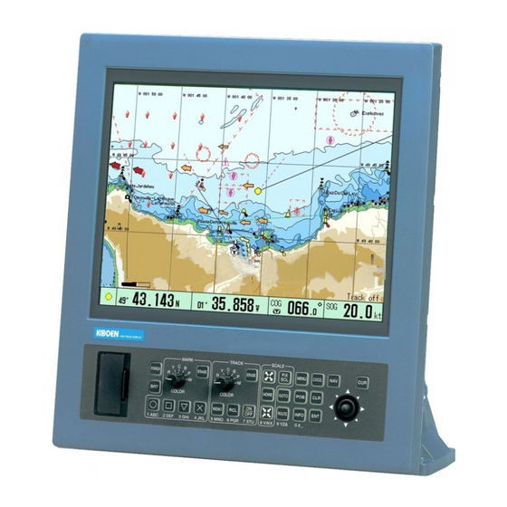
The screen size of the display unit varies according to the type, i.e. 10.4 inch (Diagonal) for GTD-110 and 15 inch for GTD-150. The panning and scrolling speed is greatly improved by using the latest digital technology. The operation is simple and straightforward, using dedicated rotary controls and tactile key pads with user-friendly menus. - Page 13 (Option) Color Fish Finder CW-376 CVS-842 (Option) CVS-852 Color Fish Finder CVS-108/118 CW-154A CVS-832 CVS-8841/8842/8816 (Option) CVS-8851/8852 DC Power cable CVS-8826/8826S series CW-253 AC/DC Power Rectifier 100/115VAC 200/230VAC PS-003A (Option) 10.8 - 31.2VDC Figure 1.1 Configuration of GTD-110/150 93151542-00...
- Page 14 GTD-110/150 Chapter 2 Equipment Composition Chapter 2 Equipment Composition Contents Page No. 2.1 Standard Equipment list …………………………………… 2-1 2.2 Option items list ……………….……………………………. 2-1 93151542-01 Contents...
- Page 15 GTD-110/150 Chapter 2 Equipment composition Chapter 2 Equipment composition 2.1 Standard equipment list Item name Type name Remarks Weight/Length Q’ty With base mount and PVC Display unit GTD-110/150 6.5 kg/10 kg cover 5 pin waterproof connector/fly DC power cable CW-253-2M...
- Page 16 GTD-110/150 Chapter 3 Specification Chapter 3 Specification Contents Page No. Specification ……..……….………………….……….…...…. 3-1 Serial data ……………………………….……………..…..… 3-1 Power requirements…..………………..……….…………… 3-2 Environmental conditions …………….….…….……….…… 3-2 External dimensions and weight ……..……………..……. 3-2 93151542-00 Contents...
-
Page 17: Specification
Specification Chapter 3 Specification 3.1 Specification Specification is subject to change without notice. Type name GTD-110/150 10.4 inch (GTD-110) / 15 inch (GTD-150) Display High Brightness Color TFT LCD Map mode Mercator projection North-up, East-up, South-up, West-up, Course-up (Waypoint), Display mode... -
Page 18: Power Requirements
3.3 Power requirements Input voltage: 10.8 - 31.2 VDC Power consumption: GTD-110: Less than 30 W (at 24VDC) GTD-150: Less than 40 W (at 24VDC) AC Operation: AC/DC rectifier PS-003A is required. Input voltage range: 115 VAC or 230 VAC 3.4 Environmental conditions... - Page 19 GTD-110/150 Chapter 3 Specification Unit:mm Unit in mm (inch) Figure 3.1 The Exterior of GTD-110 with dimensions Figure 3.2 Service space required for GTD-110 93151542-00...
- Page 20 Chapter 3 GTD-110/150 Specification Unit in mm (inch) Figure 3.3 The Exterior of GTD-150 with dimensions Figure 3.4 Service space required for GTD-110 93151542-00...
- Page 21 GTD-110/150 Chapter 4 nstallation Chapter 4 Installation Contents Page No. Installation consideration ……………………….………..… 4-1 Unpacking of the goods ………….……….……………...… 4-1 Inspection of the goods …………….…….………..….…… 4-1 Siting the units …….…………………..……..……..……..… 4-1 Cable routing and connections ……..………….…….…..4-1 Display Installation………………………………….……..… 4-2 4.6.1 Table mounting ………………………..………….……..…...
-
Page 22: Installation Consideration
Chapter 4 Installation 4.1 Installation consideration General Qualified service technicians should perform the installation of the GTD-110/150 series that comprises the following operations. (1) Unpacking each component of the system. (2) Inspection of the exterior of each component unit and accessory. -
Page 23: Display Installation
GTD-110/150 [Good wiring] Battery EMI noise from other equipment The EMI noise is terminated with battery’s internal impedance, preventing the noise from entering the GTD-110/150 display unit. KS-2001 [Inappropriate wiring] Battery EMI noise from other equipment The line length between a battery and connecting points of power cable produces higher impedance than that of the battery, causing the EMI noise to be induced in the GTD-110/150 display unit. - Page 24 (9 29/64) 47 (1 27/32) Unit in mm (inch) 37 (1 29/64) (2 23/64) Figure 4.2 Fitting detail of GTD-110 in table mounting mode Unit in mm (inch) (2 23/64) (9 29/64) (2 23/64) Figure 4.3 Service space required for GTD-110...
- Page 25 Chapter 4 GTD-110/150 Installation Unit in mm (inch) Display unit 。 Fixing screws (M5 screw, 5 pcs) Mounting bracket Washer Knurled fixing bolt (5 25/32) 2 9/16 (5 25/32) (2 9/16) Figure 4.4 Fitting detail of GTD-150 in table mounting mode...
-
Page 26: Flush Mounting
Figure 4.6 Fitting GTD-110 in flush mounting mode Fixing holes for M4 screw (4 pcs) 308 (12 1/8) 16 (5/8) 16 (5/8) 16 (5/8) 274 (10 13/16) 306 (12 1/16) Unit in mm (inch) 16 (5/8) Figure 4.7 Dimensions of opening and fixing holes for GTD-110 93151542-00... - Page 27 Chapter 4 GTD-110/150 Installation Opening for installation:410 x 378 Display Unit Before installing the unit, Fixing screws remove the washer and (M4 screws, 4 pcs) knurled fixing bolt attached on both sides of the display. Screw covers (4 pcs) Figure 4.8 Fitting GTD-150 in flush mounting mode...
-
Page 28: Cable Connections
GTD-110/150 Chapter 4 Installation 4.7 Cable connections to the GTD-110/150 Connect the power cable, antenna cable and data cable to GTD-110/150 on the rear panel. Marine Radar with ATA (Option) GPS sensor MDC-721/741/740 DGPS sensor (Option) CW-381 MDC-1541/1540/1560/1510 (Option) /1520... -
Page 29: Inspections After Installation
Figure 4.11 Pinouts of connectors on the rear panel 4.8 Inspections after installation Before you turn the unit on, check the following points to make sure the GTD-110/150 operates properly. (1) Is the ship’s supply voltage and current within the rated range? (2) Is the transducer wiring normal? No wrong connections, no short circuits, etc? (3) Are the cables routed and connected properly according to Para. - Page 30 GTD-110/150 Chapter 5 Basic Operation Chapter 5 Basic Operation Contents Page No. Operating controls and functions ……..……… 5-1 5.1.1 Power switch and brightness controls ………… 5-1 5.1.2 Marking control and keys …………..……………5-1 5.1.3 Track color controls and related keys…..……… 5-2 5.1.4...
- Page 31 Chapter 5 GTD-110/150 Basic Operation Page No. Mark registration …………………………...……… 5-12 5.6.1 Registering own ship’s position ……….…………. 5-12 5.6.2 Mark registration for the cursor assigned point … 5-13 5.6.3 Erasing the registered mark by color and shape .. 5-13 5.6.4 Assigning the mark to be deleted by the cross cursor ………………………………………………………..
- Page 32 GTD-110/150 Chapter 5 Basic Operation 5-14 Measuring the bearing and distance between two points ………………………………………………………… 5-23 93151542-00 Contents...
-
Page 33: Operating Controls And Functions
5.1.1 Power switch and brightness controls Display unit Card reader slot under this cover Operation panel Figure 5.1 Operation panel of GTD-110/150 POWER key POWER Turns system on and off. BRIGHTNESS key Controls screen brightness and illumination on the control panel. The first press of the key displays the brightness scale bar graph. -
Page 34: Track Color Controls And Related Keys
Chapter 5 GTD-110/150 Basic Operation MARK key Displays a designated mark when its relevant key is pressed. MARK DELETE key ERASE Deletes a mark shown on the display when this key is pressed. 5.1.3 Track color controls and related keys This function enables you to display and edit the ship’s track. -
Page 35: Chart Control Keys
GTD-110/150 Chapter 5 Basic Operation 5.1.4 Chart control keys This function includes various display control functions involved in setting the map scale, functional input and cancel, panning and scrolling the screen, etc. Details are as follows: SCALE 1/SCALE 2/SCALE 3 Sets the display to a preset map scale, which is assigned to each scale key. -
Page 36: Menu Related Keys
Chapter 5 GTD-110/150 Basic Operation INFO key Displays information about the various icons used. INFO 5.1.6 Menu related keys MENU key Opens the menu screen. MENU ENT key Enters a preset menu item. CANCEL key Cancels an entered menu item. -
Page 37: C-Map Nt Max Information
GTD-110/150 Chapter 5 Basic Operation 5.2 C-MAP NT MAX INFORMATION MAX is a major evolution of NT/NT+ product technology. The key points are: New Data Features Tides and Currents (Intuitive arrows show direction and strength) World Background Charts with terrestrial data Value Added Data (Pictures and Diagrams. -
Page 38: Getting Started
“Replacement needed” is shown and an audio alarm will be activated. In such a case, contact KODEN or your nearest KODEN dealer for replacement. The “CAUTION” display is shown next, notifying... -
Page 39: Turning The Power Off
GTD-110/150 Chapter 5 Basic Operation 5.3.2 Turning the power off Press the POWER key. All the user settings are saved to the internal memory. CAUTION The time between turning the power on and off must be at least 1 second to avoid malfunction of the system. -
Page 40: Operation On The Map Display
Figure 5.4 Moving the cross cursor WARNING When the GTD-110/150 is operated in CURSOR ON mode, the own ship position will not be brought back to the center of the display even if own ship goes beyond the screen itself. To resume OWN SHIP mode, turn the cross cursor off. -
Page 41: Image Shift With Cross Cursor On
GTD-110/150 Chapter 5 Basic Operation (1) Press the CUR key to delete the cross cursor. (2) Press the MENU key to select “IMAGE SCROLL DIRECTION” and select OWN SHIP or MAP. (3) Operate the Joystick to shift the image to a desired direction. -
Page 42: Displaying A Ship's Track
Chapter 5 GTD-110/150 Basic Operation Fix zooming: Press the FIX SCL key to select the map scale. Each press of the key toggles Scale 1, Scale 2 and Scale 3. The following table shows default map scales in nm and km unit systems. -
Page 43: Storing Ship's Track
Figure 5.8 Storing a ship’s track line GTD-110/150 can store up to 49,000 points arranged in 7 blocks, 7000 points each. Select “TRACK STORE” to store the track points. By performing the TRACK STORE function the track points data is protected from erasure that happens when the back-up battery is nearing its life or is removed. -
Page 44: Deleting A Ship's Track By Specifying An Area
An erased track cannot be resumed. Take care not to ruin recorded ship’s tracks. 5.6 Mark registration The GTD-110/150 can register up to 8,300 points with registration numbers assigned from 0 to 8,299. Each point can be assigned with different marks and colors. Registering points with marks is called “Mark registration”. -
Page 45: Mark Registration For The Cursor Assigned Point
GTD-110/150 Chapter 5 Basic Operation 5.6.2 Mark registration for the cursor assigned point (1) Display the cross cursor by pressing the CUR key. (2) Assign the mark color by the MARK COLOR switch. (3) Move the cross cursor by operating the Joystick to cover the point to be registered. -
Page 46: Assigning The Mark To Be Deleted By The Cross Cursor
Chapter 5 GTD-110/150 Basic Operation 5.6.4 Assigning a mark to be deleted by the cross cursor (1) Display the cross cursor by pressing the CUR key. (2) Operate the joystick to move the cross cursor to the mark position to be deleted. -
Page 47: Setting A Waypoint By The Cross Cursor
GTD-110/150 Chapter 5 Basic Operation This point is to be set as a waypoint. The No. 115 point is now set as a waypoint. Figure 5.16 Setting waypoints by registered marks 5.7.2 Setting a waypoint by the cross cursor (1) Press the CUR key to display the cross cursor. -
Page 48: Resetting A Point Of Origin For The Waypoint Navigation
Chapter 5 GTD-110/150 Basic Operation Figure 5.18 Resetting the waypoints by a mark number 5.7.4 Resetting a point of origin for waypoint navigation When a waypoint has already been set up, own ship’s current position can be set as a new point of origin. -
Page 49: Marking The Pob (Person Over Board) Location
GTD-110/150 Chapter 5 Basic Operation 5.8 Marking the POB (Person Over Board) location This is an emergency event function to mark the location of an accident such as a man overboard. To use this function, simply press the POB key. The POB point is marked with its position (latitude/longitude), bearing and distance (nm) shown at the bottom of the screen. -
Page 50: Quick Info
2. If the ship’s speed is less than 1 knot (1.8 km/h), Head Up mode is disabled to prevent erratic map movement. 3. To operate GTD-110/150 in Head Up mode, you need to input the VTG sentence (in NMEA 0183) sent from an external navigation receiver. As long as the KODEN GPS sensor KBG-2/KBG-3/GPS-10A is connected, you do not need to worry about this setting. -
Page 51: Object Information
GTD-110/150 Chapter 5 Basic Operation Operation of Quick Info (1) Display the cursor pushing the CUR key. (2) Using the joystick, place the cursor on the icon to which you want to refer. The information will be displayed about one second after you position the cursor. -
Page 52: Tidal Info
Chapter 5 GTD-110/150 Basic Operation Then, photographs will start appearing. It takes several tens of seconds for photographs to be transmitted in full. A transmission progress bar is displayed in the lower screen section. Press the MENU key to end the photograph display. -
Page 53: Event Temporary Store
GTD-110/150 Chapter 5 Basic Operation 5.13 Event temporary store EVENT TEMPORARY STORE is a function to memorize events (the ship’s position) one by one using 0~99 mark numbers as ring buffers. This section explains the display when inputting and operating the EVENT TEMPORARY STORE. -
Page 54: Re-Display Of Event Window
Chapter 5 GTD-110/150 Basic Operation 5.13.4 Re-display of event window When the event window is not showing, events will not be input. In order to display the event window again, press CANCEL and the event window will be displayed with a red frame (active window). - Page 55 GTD-110/150 Chapter 5 Basic Operation 5.14 Measuring the bearing and distance between two points (1) Press the CUR key to display the cross cursor (2) Move the cross cursor using the Joystick on to the first point and press the ENT key. A pop up window labeled “POINT TO POINT”...
- Page 56 GTD-110/150 Chapter 6 Using the Menu Chapter 6 Using the Menu Contents Page No. Menu functions ……………………………………………..…… 6-1 6.1.1 Basic menu operation …………………….……………….….… 6-2 MARK BLOCK NUMBER ………………………………………. 6-3 Setting the alarm ……………………………….…………..…… 6-3 6.3.1 ARRIVAL ALARM ………………………………………..…..… 6-3 6.3.2 POB (Person Over Board) alarm ………………………...……...
- Page 57 Chapter 6 GTD-110/150 Usin the menu Page No. 6.4.8 CURSOR WINDOW SETTING………………………….….…. 6-16 Setting the KODEN GPS/DGPS sensor ……….…………...… 6-16 SYSTEM SETTINGS …………..………………………………. 6-17 6.6.1 Distance/Speed ……….……….………….……………….……. 6-18 6.6.2 PLOT INTERVAL …………….…………………….……….…… 6-18 6.6.3 NUMBER OF PLOTS …………….……………….……………. 6-18 6.6.4 AVERAGE SPEED and AVERAGE NUMBER ……….…….……...
- Page 58 GTD-110/150 Chapter 6 Using the Menu a. Moving an existing node.………………………………………. 6-30 b. Adding a node ………………………………………….……….. 6-31 c. Deleting a node ……………………………………….………… 6-32 6.10.4.2 Editing the graphic by lat/lon or LOP ……………………………. 6-33 a. Moving an existing node ………………………………………. 6-33 b.
-
Page 59: Menu Functions
Chapter 6 Using the menu Chapter 6 Using the menu 6.1 Menu functions The menu functions used in the GTD-110/150 are as shown in the following table. Table 6.1 The list of menu functions Menu functions Descriptions MARK BLOCK NUMBER... -
Page 60: Basic Menu Operation
SYSTEM TEST Operation test COLOR PALETTE To select and adjust the color tone OPERATION DATA Communication with another GTD-110/150 unit in terms COMMUNICATION of mark data, etc FLASH ROM To erase data stored in the Flash ROM (Read Only ERASE... -
Page 61: Mark Block Number
GTD-110/150 Chapter 6 Using the menu 6.2 MARK BLOCK NUMBER, Setting the start number of the mark block This function allows assigning the start number of the mark. To set: (1) Press the MENU key and select MARK BLOCK NUMBER. -
Page 62: Xte (Cross Track Error) Alarm
Chapter 6 GTD-110/150 Using the menu 6.3.3 XTE ALARM (Cross Track Error) alarm This alarm (audio) is activated when own ship deviates from a preset course deviation width. Setting range (width): 0.05 ~5.00 nm or km Initial setting: 0.05 nm or km 6.3.4 ALARM ZONE... -
Page 63: Display Settings
GTD-110/150 Chapter 6 Using the menu 6.4 DISPLAY SETTINGS This menu allows turning the position data display, chart display and various screen display settings on or off the screen. To open this menu, press the MENU key and select DISPLAY SETTINGS. -
Page 64: Chart Display
Chapter 6 GTD-110/150 Using the menu 6.4.2 CHART DISPLAY Figure 6.6 CHART DISPLAY menu Selects or changes the colors of land or ocean, Value-Added Data, Perspective View, etc., which are shown on the chart. Use the Joystick to select and set an item in the sub menu. -
Page 65: Marine Display
GTD-110/150 Chapter 6 Using the menu 6.4.3 MARINE DISPLAY Figure 6.7 MARINE DISPLAY menu Selects or changes the various marine markers such as lighthouse, ports, buoys, etc., which are shown on the chart. Use the Joystick to select and set an item in the sub menu. -
Page 66: Land Display
Chapter 6 GTD-110/150 Using the menu 6.4.4 LAND DISPLAY Selects or changes the various marks on land such as landmarks, roads, airports, etc., which are shown on the chart. Use the Joystick to select and set an item in the sub menu. -
Page 67: Screen Display Setting
GTD-110/150 Chapter 6 Using the menu Figure 6.9 DEPTH DISPLAY menu Figure 6.8 LAND DISPLAY menu 6.4.6 SCREEN DISPLAY SETTING Sets up various screen displays such as the course line, position mark, track line, mark size, cursor type, information window, etc. -
Page 68: Position Mark
Chapter 6 GTD-110/150 Using the menu Initial setting: TRUE 6.4.6.3 POSITION MARK Using this function you can indicate own ship’s position with a circle or a ship’s profile, the size of each mark can be changed. If you select SHIP, the ship’s profile is always directed to own ship’s heading. -
Page 69: Ring Marker
GTD-110/150 Chapter 6 Using the menu 6.4.6.8 RING MARKER Displays equally spaced rings referenced to own ship as a distance marker. The scale bar shown at the left bottom of the screen indicates the interval of each ring. Selections: NO and YES... -
Page 70: Safety Status Bar
Chapter 6 GTD-110/150 Using the menu 6.4.6.9 SAFETY STATUS BAR This feature displays a status bar with six boxes showing the status of certain functions. Any warning or alarm condition is identified by the color red to indicate possible risk. -
Page 71: Added Info Of Pos
GTD-110/150 Chapter 6 Using the menu 6.4.6.11 Added info of POS Select information displayed on the right edge of the Present Position display. Added info display area Figure 6.12 Added info display of Present Position Added information items Table 6.6... -
Page 72: Added Info Of Wpt
Chapter 6 GTD-110/150 Using the menu 6.4.6.12 Added info of WPT Select information displayed on the right edge of the Waypoint display. Added info display Figure 6.13 Added Info display of Waypoint Added information items Table 6.7 XTE (To the course) Displays the distance from the own ship position to the course line and the corrected direction. -
Page 73: Added Info Of Pob
GTD-110/150 Chapter 6 Using the menu 6.4.6.13 Added info of POB Select information displayed on the right edge of the POB display. Added info display Figure 6.14 13 Added Info display of POB Added information items Table 6.8 Speed Average... -
Page 74: Cursor Window Setting
NO (None), L/L (Latitude/Longitude) and LORAN C Initial setting: NO Figure 6.16 Example display of the Cursor Window 6.5 Setting the KODEN GPS/DGPS sensor The following setting items are available for GPS/DGPS sensor. Table 6.9 GPS/DGPS setting items Items to be set Selections Description DATUM is fixation with WGS-84. -
Page 75: System Settings
Figure 6.17 GPS/DGPS SETTINGS menu 6.6 SYSTEM SETTINGS This sub menu allows setting various functional parameters used in the GTD-110/150 GPS Track Display. The parameters to be set are as follows: Table 6.10 Parameters to be set up... -
Page 76: Number Of Plots
Chapter 6 GTD-110/150 Using the menu Figure 6.18 SYSTEM SETTINGS menus 6.6.1 Distance/Speed Selects the units of distance and speed shown on the screen. Selections: nm、kt / km、km/h Initial setting: nm、kt 6.6.2 PLOT INTERVAL Selects either time interval or distance interval for plotting. The smaller the value, the finer the plots are, but this consumes memory. -
Page 77: Fix Scale 1-3
GTD-110/150 Chapter 6 Using the menu 6.6.5 FIX SCALE 1 - 3 This function is used to allocate most frequently used map scales to 3 different fix scales, SCALE 1, SCALE 2 and SCALE 3 from the map scale library. Once set, you can select the desired scale by simply pressing the FIX SCL key. -
Page 78: Local Time Correction
Chapter 6 GTD-110/150 Using the menu Initial setting: NO Figure 6.19 Correcting own ship’s position 6.6.10 LOCAL TIME CORRECTION This function allows you to set up the local time by modifying the UTC (Universal Standard Time) supplied from a GPS receiver. Entering the time difference between your local time and the UTC makes the correction to set up the local time. -
Page 79: Compass Correction
GTD-110/150 Chapter 6 Using the menu 6.6.11 COMPASS CORRECTION This procedure allows you to modify the bearing shown on the screen, which is obtained from the GPS receiver, to the magnetic compass bearing. Selection: AUTO / MANUAL, -90.0 - +90.0 Initial setting: AUTO 0.0... -
Page 80: Output Setting
Chapter 6 GTD-110/150 Using the menu 6.6.13 OUTPUT SETTING Switch the amount of the sentence that NMEA-0183 outputs. This switch is useful for the output of data to auto-pilot and radar. Table 6.11 Output data table by difference of setting... - Page 81 GTD-110/150 Chapter 6 Using the menu displayed by operating the joystick up or down. When the color of the frame of the window changes to black, these operations can no longer be carried out. You can switch the method of changing the color of the frame of the window by this setting.
-
Page 82: Mark Edit
Chapter 6 GTD-110/150 Using the menu 6.7 MARK EDIT Allows the editing of mark designations. This menu includes EDIT, TRANSFER, DELETE and OPERATION OF BLOCKS. Positional data to be entered is latitude/longitude or Loran-C LOP selected in DISPLAY SETTINGS of the POSITION DATA DISPLAY menu. -
Page 83: Operation Of Blocks
GTD-110/150 Chapter 6 Using the menu 6.8 OPERATION OF BLOCKS Selects DISPLAY OF BLOCKS, TRANSFER OF BLOCKS or ERASE OF BLOCKS. 6.8.1 DISPLAY OF BLOCKS Select YES or NO in the mark display and in the number display. This feature is useful in grouping areas of interest for various purposes. -
Page 84: Gps Monitor
Chapter 6 GTD-110/150 Using the menu 6.9 GPS MONITOR Displays the status of GPS and Beacon reception. Figure 6.30 GPS MONITOR sub menu Table 6.12 The list of GPS/Beacon reception status GPS STATUS GPS reception normal: OK No GPS reception: BAD... -
Page 85: Drawing Edit Sub Menu
“DRAWING RECALL” and “DRAWING EDIT”. 6.10.1 DRAWING Using this function, you can create lines, squares, polygons etc. on the screen. GTD-110/150 has drawing memory arranged in 7 blocks, 500 points each. A graphic drawing can be created by the cross cursor and specifying the latitude/longitude Figure 6.31 DRAWING EDIT sub menu... -
Page 86: Drawing (Drawing A Graphic Using The Cross Cursor)
Chapter 6 GTD-110/150 Using the menu NOTE: If you enter a block number by mistake, press the CANCEL key. Each press of this key brings the block number back by one. Similarly, if you enter data by mistake, press the CANCEL key. -
Page 87: Drawing Recall
GTD-110/150 Chapter 6 Using the menu acknowledged as long as it lies within the cross cursor.) (3) Press the ENT key. The drawing will be erased. (4) If you have erased a drawing by mistake, press the CANCEL key. The erased drawing will be redrawn. -
Page 88: Drawing Edit
Chapter 6 GTD-110/150 Using the menu 6.10.4 DRAWING EDIT This function allows you to edit the graphics to be registered. 6.10.4.1 Editing the graphics using the cross cursor The following 3 methods are available to edit a graphic Figure 6.36 DRAWING EDIT menu drawing using the cross cursor. -
Page 89: Adding A Node
GTD-110/150 Chapter 6 Using the menu Figure 6.39b MOVEMENT menu (3) Figure 6.39c MOVEMENT menu (3) b. Adding a node (1) Press the MENU key to display the menu. (2) Press the Joystick up or down to highlight DRAWING EDIT. -
Page 90: Deleting A Node
Chapter 6 GTD-110/150 Using the menu (7) Press the ROUTE key to enter the added node. NOTE: If other nodes are situated nearby, press the ROUTE key repeatedly. Each press of the key selects a node one by one. (8) Move the added node to a desired point using the Joystick. -
Page 91: Editing The Graphic By Lat/Lon Or Lop
GTD-110/150 Chapter 6 Using the menu (1) Move the Joystick to place the cross cursor on a node of the graphic drawing to be deleted. (Figure 6.45) (2) Press the ROUTE key to display the selected node data. NOTE: If other nodes are situated nearby, press the ROUTE key repeatedly. - Page 92 Chapter 6 GTD-110/150 Using the menu (8) Press the Joystick to the right to enter the MOVEMENT menu. (9) Enter the number of the node to be moved using the numeric keys or moving the Joystick up or down. (Figure 6.49) Figure 6.49 MOVEMENT (1) menu...
-
Page 93: Adding A Node
GTD-110/150 Chapter 6 Using the menu b. Adding a node (1) Press the MENU key to display the menu. (2) Move the Joystick up or down to highlight DRAWING EDIT. (3) Press the Joystick to the right to enter the DRAWING EDIT menu. -
Page 94: Deleting A Node
Chapter 6 GTD-110/150 Using the menu c. Deleting a node (1) Press the MENU key to display the menu. (2) Press the Joystick up or down to highlight DRAWING EDIT. (3) Press the joystick to the right to enter the DRAWING EDIT menu. -
Page 95: Track Color Setting
GTD-110/150 Chapter 6 Using the menu 6.11 TRACK COLOR SETTING To set the track color. In setting the track color, there are two settings "Normal" and "W_Temp RESP". "Normal" is the mode in which the track color is changed by the track color rotary knob operation. -
Page 96: Other Ships Plotting Settings
6.12 OTHER SHIPS PLOTTING SETTINGS By connecting a radar set with the ATA function provided, the GTD-110/150 can plot a ship’s track for up to 10 targets with 1,000 points each. Each track’s property can be added to or modified as below. - Page 97 GTD-110/150 Chapter 6 Using the menu An example display of the ship’s plot display is shown in Figure 6.65, in which 3 ships are under plot with own ship’s track, other ship’s ID numbers and their SPD RESP course lines being shown.
-
Page 98: User C-Card
Chapter 6 GTD-110/150 Using the menu 6.13 User C-CARD The User C-Card is a data storage media supplied from C-Map or its dealer. Using the User C-Card, the following user defined data can be saved. MARK: To be saved on a block basis. - Page 99 GTD-110/150 Chapter 6 Using the menu (6) Storing data Storing MARK / ROUTE / TRACK / DRAWING / OTHER SHIP’S PLOT 1) Move the Joystick up or down to highlight the block number to be saved. (Figure 6.69) 2) Move the Joystick to the right to enter its setting menu.
-
Page 100: Recall
Chapter 6 GTD-110/150 Using the menu Prompt messages If any of the following messages appear, redo the operation as instructed. “Please insert User C-Card” This message indicates that the User C-Card is not inserted or not fully inserted into the slot. Reinsert the User C-Card. - Page 101 GTD-110/150 Chapter 6 Using the menu (6) Recalling the data Use the following procedure to recall the item. Recalling MARK / ROUTE / TRACK / DRAWING / OTHER SHIP’S PLOT 1) Move the Joystick up or down to highlight the file you wish to recall and press the ENT key.
-
Page 102: Erase
Chapter 6 GTD-110/150 Using the menu Prompt messages If any of the following messages appears, redo the operation as instructed. “Please insert User C-Card” This message indicates that the User C-Card is not inserted or not properly inserted into the slot. -
Page 103: Format
Reinsert the User C-Card. 6.13.4 FORMAT Prior to using a User C-Card, you need to format the User C-Card for GTD-110/150 storage application. Take care not to overwrite any data already stored in the User C-Card by an unintentionally formatting. -
Page 104: Nearest Port Info
Chapter 6 GTD-110/150 Using the menu 6.14 NEAREST PORT INFO Display information on the port in the vicinity of own ship’s position or the cursor position. (1) Turn off the cursor when you want to obtain information on the vicinity of the position of the ship. -
Page 105: Maintenance
GTD-110/150 Chapter 6 Using the menu 6.15 MAINTENANCE This menu contains the following test menu to confirm the system operation is in good order. SIMULATION SYSTEM TEST COLOR PALETTE OPERATION DATA COMMUNICATION FLASH ROM ERASE LANGUAGE Details are given in the following descriptions. - Page 106 GTD-110/150 Chapter 7 Route/Mark navigation Chapter 7 Route navigation Contents Page No. Routes ………………………………………………………….…… 7-1 7.1.1 Creating a route ….………………………………………………… 7-1 7.1.1.1 Creating a route using the cross cursor ……………….………… 7-1 7.1.1.2 Creating a route by specifying a waypoint …………………..….. 7-3 7.1.1.3 Specifying a waypoint …………………………………………..….
-
Page 107: Routes
This paragraph describes the methods concerning route creation and edition. 7.1.1 Creating a route There are three methods available to create the route in the GTD-110/150. These are; using the cross cursor, specifying a point (lat/lon or LOP) and using the registered Mark number. Details are given in the following paragraphs. - Page 108 Chapter 7 GTD-110/150 Route/Mark navigation Figure 7.5 ROUTING menu (2) Figure 7.4 ROUTING menu (1) NOTE: The keying sequence to enter alphabets and numbers are as follows: MEMO & ROUTE INFO (Setting waypoints) (1) Use the Joystick to move the cross cursor to designate a waypoint.
-
Page 109: Creating A Route By Specifying A Waypoint
GTD-110/150 Chapter 7 Route/Mark navigation 7.1.1.2 Creating a route by specifying a waypoint (Opening the ROUTE menu) (1) Press the MENU key to display the MENU window. (2) Move the Joystick up or down to highlight ROUTE. (3) Press the Joystick to the right to enter the ROUTE menu. -
Page 110: Specifying A Waypoint
Chapter 7 GTD-110/150 Route/Mark navigation NOTE: Keying sequence to enter alphabets and numbers are as follows: MEMO & ROUTE INFO 7.1.1.3 Specifying a waypoint a. By latitude and longitude coordinate (1) Press the Joystick to the left to highlight MARK NUMBER. -
Page 111: Setting A Route
GTD-110/150 Chapter 7 Route/Mark navigation c. By Mark number entry. (1) Enter the mark number using the assigned alphanumeric keys. (Figure 7.10) (2) Press the ENT key to register the waypoint. (3) Repeat step 1 and step 2 for further waypoint registrations. -
Page 112: Designating A Route From The List
Chapter 7 GTD-110/150 Route/Mark navigation Figure 7.13 Route display shown on the screen 7.1.2.2Designating a route from the list (1) Press the ROUTE key without the cross cursor shown screen. registered route information will be shown in the ROUTE EXECUTE window. -
Page 113: Changing A Waypoint
This function allows you to skip the current waypoint to the next one. To do: (1) Press the ROUTE key while the GTD-110/150 is in the navigation mode. (2) Press the GOTO key to change the waypoint. The course line will be re-drawn from own ship’s position to the next waypoint. -
Page 114: Canceling A Route
7.1.5 Canceling a route Upon setting the GTD-110/150 to Route mode, this function allows you to cancel an active route display on the screen. Press the CLR key and the displayed route will be erased from the screen. (The registered... -
Page 115: Moving A Waypoint
GTD-110/150 Chapter 7 Route/Mark navigation a. Moving a waypoint (1) Press the MENU key to display the MENU window. (2) Press the Joystick up or down to highlight ROUTE. (3) Press the Joystick to the right to enter the ROUTE menu. The ROUTE window will appear. - Page 116 Chapter 7 GTD-110/150 Route/Mark navigation (10) Use the Joystick to allow the cross cursor to fall on the waypoint to be moved. (11) Press the ROUTE key to select the waypoint. The waypoint data (waypoint number, lat/lon) will be shown in the WAYPOINT MOVEMENT window.
- Page 117 GTD-110/150 Chapter 7 Route/Mark navigation b. Adding a waypoint (1) Press the MENU key and select ROUTE. (2) Press the Joystick to the right to enter the ROUTE EDIT menu. (3) Press the Joystick up or down to highlight CURSOR. (Figure 7.26) Figure 7.25 ROUTE menu...
- Page 118 Chapter 7 GTD-110/150 Route/Mark navigation (9) Move the designated waypoint to a desired point. (Figure 7.29) (10) Press the ENT key to register a new waypoint. The lat/lon data of the new waypoint will be shown in the WAYPOINT ADDITION window.
- Page 119 GTD-110/150 Chapter 7 Route/Mark navigation c. Deleting a waypoint (1) Press the MENU key and highlight ROUTE. (2) Press the Joystick to the right to display the ROUTE window. (3) In the ROUTE window, move the Joystick up or down to highlight ROUTE EDIT.
-
Page 120: Editing A Route By Specifying A Point (Lat/Lon Or Lop)
Chapter 7 GTD-110/150 Route/Mark navigation Existing route Select a point by moving the cross cursor on to the point and then delete Figure 7.35 Erasing a waypoint 7.1.6.2 Editing a route by specifying a point (lat/lon or LOP) a. Moving a waypoint (1) Press the MENU key to open the MENU window. - Page 121 GTD-110/150 Chapter 7 Route/Mark navigation (8) Press the Joystick up or down to highlight WAYPOINT MOVEMENT. (9) Press the Joystick to the right and the Figure 7.39 ROUTE EDIT (LIST) sub menu WAYPOINT MOVEMENT menu will appear. (Figure 7.40) (10) Select the waypoint to be moved by entering its number by the alphanumeric keys.
- Page 122 Chapter 7 GTD-110/150 Route/Mark navigation b. Adding a waypoint (1) Press the MENU key to open the menu and highlight ROUTE. (2) Press the Joystick to the right and the ROUTE menu will appear. (Figure 7.42) Figure 7.42 ROUTE menu (3) Highlight ROUTE EDIT and press the Joystick to the right.
- Page 123 GTD-110/150 Chapter 7 Route/Mark navigation (7) Press the Joystick up or down to highlight WAYPOINT ADDITION (8) Press the Joystick to the right to enter the WAYPOINT ADDITION menu. (Figure 7.46) Enter waypoint number using alphanumeric keys or the Joystick.
- Page 124 Chapter 7 GTD-110/150 Route/Mark navigation c. Deleting a waypoint (1) Press the MENU key to open the menu and highlight ROUTE. (2) Press the Joystick to the right and the ROUTE menu will appear. (Figure 7.48) Figure 7.48 ROUTE menu (3) Highlight ROUTE EDIT and press the Joystick to the right.
- Page 125 GTD-110/150 Chapter 7 Route/Mark navigation (6) Press the ENT key to fix the entry. The ROUTE EDIT (LIST) menu will appear. (Figure 7.51) (7) Press the Joystick up or down to highlight WAYPOINT DELETE. Figure 7.51 ROUTE EDIT (LIST) sub menu...
-
Page 126: Editing The Comment
Chapter 7 GTD-110/150 Route/Mark navigation d. Editing the comment (1) Press the MENU key to show the menu and highlight ROUTE. (2) Press the Joystick to the right. The ROUTE menu will appear. (Figure 7.54) Figure 7.54 ROUTE menu (3) Press the Joystick up or down to highlight ROUTE EDIT. - Page 127 GTD-110/150 Chapter 7 Route/Mark navigation (7) Press the ENT key to fix the route number. The ROUTE EDIT (LIST) menu will appear. (Figure 7.56) (8) Highlight COMMENT EDIT in the ROUTE EDIT sub menu. Figure 7.57 ROUTE EDIT sub menu (9) Press the Joystick to the right to enter the COMMENT EDIT menu.
-
Page 128: Deleting A Route
Chapter 7 GTD-110/150 Route/Mark navigation 7.1.7 Deleting a route This function allows you to delete the registered route. 7.1.7.1 Deleting a route using the cross cursor (1) Press the MENU key and highlight ROUTE. (2) Press the Joystick to the right. The ROUTE menu will appear. -
Page 129: Deleting A Route From The List
GTD-110/150 Chapter 7 Route/Mark navigation 7.1.7.2 Deleting a route from the list (1) Press the MENU key to display the menu and highlight ROUTE. The ROUTE menu will appear. Figure 7.63 ROUTE menu (2) Press the Joystick up or down to highlight ROUTE ERASE. -
Page 130: Texts For Marks
Chapter 7 GTD-110/150 Route/Mark navigation 7.2 Texts for Marks This function allows you to enter texts (12 texts at maximum) to make a comment (name, note, etc.). 7.2.1 Entering texts (1) Press the Mark ( ) key to which a comment will be added. - Page 131 GTD-110/150 Chapter 7 Route/Mark navigation 7.2.2 Re-editing the comments for a registered Mark This function allows you to edit the comment for a mark registered. (1) Press the MENU key to display the menu. (2) Highlight MARK EDIT and press the Joystick to the right. The MARK EDIT (L/L) menu will appear.
- Page 132 Chapter 7 GTD-110/150 Route/Mark navigation (6) Press the Joystick to the left to highlight MARK NUMBER. (7) Press the Joystick up or down to highlight COMMENT. (Figure 7.71a) Figure 7.71a Entering texts for comment (8) Press the Joystick to the right to enter the comment area.
- Page 133 GTD-110/150 Chapter 8 Trouble shooting Chapter 8 Trouble shooting Contents Page No. Information required for service ……………………….………… 8-1 First line fault location ……………………….…………………..8-1 8.2.1 Nothing displayed even if the POWER switch is pressed …….. 8-1 8.2.2 Own ship’s position is not shown in the screen ………………… 8-1 8.2.3 Own ship’s mark does not blink and no position fix available …...
-
Page 134: Information Required For Service
8.2 First line fault location Use the following procedure to locate a faulty area using the following Q&A instructions. If the fault cannot be fixed, contact your local KODEN dealer for repair. 8.2.1 Nothing displayed even if the POWER switch is pressed Q: Is the main fuse (in-line) blown? A: Remove the power connector and check the fuse. -
Page 135: Own Heading Course Is Not Correct
It is near the end of its life. Contact your nearest KODEN dealer for replacement. Even if the battery life is terminated, the registered mark data and ship’s track data are stored in the non-volatile memory and protected from erasure. However, new track data and mark data cannot be added. - Page 136 GTD-110/150 Chapter 9 Maintenance Chapter 9 Maintenance Contents Page No. Periodic inspection and cleaning …………..…….……….… 9-1 9.1.1 Monthly check ….……………………………………………… 9-1 93151542-00 Contents...
- Page 137 GTD-110/150 Chapter 9 Maintenance Chapter 9 Maintenance 9.1 Periodic inspection and cleaning To prolong the equipment life, the following maintenance should be performed on a routine basis. Also, from time to time, check plug connections and cables. 9.1.1 Monthly check If the display screen is dirty, clean the screen with a soft cloth damped with anti-static agent or pure water.
- Page 138 GTD-110/150 Chapter 10 Technical Reference Chapter 10 Technical Reference Contents Page No. 10.1 Details of input serial data............10-1 10.1.1 Input data format ……….…………………………..……..……… 10-1 10.1.2 Input data specification ……….……………………..……….….. 10-1 10.1.3 Details of input sentences …….……………………..….……..10-1 10.2 Details of output serial data sentence ………………...….…..10-5 10.2.1 Output data format ………….………………………..…...………...
-
Page 139: Details Of Input Serial Data
GTD-110/150 Chapter 10 Technical Reference 10.1 Details of input serial data Sentence name: NMEA-0183 Ver. 1.5/2.0 10.1.1 Input data format Data per one byte is as follows: Parity bit: none Start Bit Stop Bit Logic 0: >+4V Logic 1: +0.5V... - Page 140 Chapter 10 GTD-110/150 Technical Reference Geographic position – latitude/longitude Ver.1.5 $ _ _ GLL, XXXX.XXX, N/S, XXXX.XXX, E/W, *hh <CR><LF> /2.0 Sentence Checksum name Longitude Latitude Latitude Talker device Longitude Start of sentence MSK receiver signal status Ver.2.0 $ _ _MSS, X.X, XX, XXX.X, XXX <CR> <LF>...
-
Page 141: Vtg Course Over Ground And Ground Speed
Talker device Start of sentence PKODA GPS Satellite information (KODEN proprietary sentence) Ver.2.0 $ PKODA, P/H, XXX.X, XX, XX, XX, XX, XX, XX, XX, XX, XXX, M, XXX.X, N KODEN meter revision number PDOP value... - Page 142 Chapter 10 GTD-110/150 Technical Reference PKODG, 1 GPS Satellite information (KODEN proprietary sentence) Ver.2.0 $ PKODG, 1, X, XX, +/- XX, XXX, XX, XX, XX, XX, XX, KODEN revision number Satellite number Elevation Averaging constant angle limit KODEN proprietary Satellite elevation...
-
Page 143: Details Of Output Serial Data Sentence
GTD-110/150 Chapter 10 Technical Reference 10.2 Details of output serial data sentence Sentence name: NMEA-0183 Ver. 2. 10.2.1 Output data format Data per one byte is as follows: Parity bit: none Start bit Stop bit Logic 0 (+4V or more) Logic 1 (+0.5V or more) - Page 144 Chapter 10 GTD-110/150 Technical Reference Global positioning system (GPS) fix data Ver.1.5 $ GP GGA, hhmmss, XXXX.XXX, N/S, XXXXX.XXX, E/W $ GP GGA, hhmmss, XXXX.XXX, N/S, XXXXX.XXX, E/W /2.0 Sentence Longitude Latitude name Longitude N/S Latitude N/S Talker device UTC of position Start of sentence X, XX, XXX, 0/-XXXX, M, 0/-XXX, M, *hh <CR><LF>...
- Page 145 GTD-110/150 Chapter 10 Technical Reference Course over ground and ground speed Ver.2.0 $ GP VTG, xxx.x, T, , , xxx.x, N, xxx.x, K, *hh <CR><LF> Sentence Checksum name Course degrees true Speed, knots Speed, km/h Talker device Start of sentence Cross-track error, measured (to be output only when a waypoint is assigned) Ver.1.5...
-
Page 146: Data Input/Output Serial Line
Chapter 10 GTD-110/150 Technical Reference 10.3 Data input/output serial line 10.3.1 Serial data input circuit Connector name: NMEA/GPS SENSOR The connector used: Type LTWD-06BFFA-L180 Input impedance: 470 Ω Device: Opto-coupler Type TLP181-G8 (Toshiba) +Vcc A Data Input Signal output Pin 4... - Page 147 GTD-110/150 Chapter 10 Technical Reference 10.4 Connector pinouts (1) GND (2) TX (Output (3) GND (Output) (4) RX+ (Input) (5) RX- (Input) (6) NC (1) GND (Output) (2) GPS OUT(Output) (3) GND (Output) (4) GPS IN+ (Input) Not used (5) GPS IN- (Input)
- Page 148 GTD-110/150 Annex Annex Contents Page No. A.1 GTD-110/150 Menu tree ………………….…………………… A-1 A.2 Color palette list for GTD-110/150 ……………………………. A-6 93151542-00 Annex...
- Page 149 GTD-110/150 Menu tree MENU MARK BLOCK NUMBER (00000, 00100, 01000, 02000, 03000, 04000, 05000, 06000, 07000, 08000) ALARM ARRIVAL ALARM (ON, OFF) SETTINGS ARRIVAL ALARM RANGE (0.05 – 5.00 nm, km) POB ALARM (ON, OFF) POB ALARM RANGE (0.05 – 5.00 nm, km)
- Page 150 GTD-110/150 Menu tree Road Name (ON, OFF) Railway (ON, OFF) (ON, OFF) DEPTH Depth Range (ON, OFF) DISPLAY Depth Range Min (0 - 9999m, fm, ft) Depth Range Max (0 - 9999m, fm, ft) Rocks (ON, OFF) Depth Contour Label...
- Page 151 GTD-110/150 Menu tree GPS/DGPS DATUM(WGS-84) SETTINGS AVERAGE(1, 2, 3) BEACON SELECT AUTO MANUAL FREQUENCY(283.5 - 325.0 kHz) BAUD RATE (50, 100, 200) DGPS MODE(OFF, BEACON, SBAS) GPS INIT(NO, YES) SYSTEM Distance/Speed (nm, kt, km, km/h) SETTINGS PLOT INTERVAL (TIME, DISTANCE)
- Page 152 GTD-110/150 Menu tree ROUTE ROUTING CURSOR ROUTE No (01 - 50) COMMENT (12 letters 0-9 , A-Z , & , # , _ , . ) VALUE ROUTE No (01 - 50 ) COMMENT (12 letters 0-9 , A-Z , & , # , _ , . )
- Page 153 GTD-110/150 Menu tree ERASE MARK ROUTE TRACK DRAWING OTHER SHIPS PLOT SYSTEM FORMAT NEAREST PORT INFO ICON select NAME select Detail Info MAINTENANCE SIMULATION START LAT (00°00.000 - 90°00.000 N/S) START LON (00°00.000 - 180°00.000 E/W) SPEED (00 - 50 kt) STEERING (0 –...
Need help?
Do you have a question about the GTD-110 and is the answer not in the manual?
Questions and answers