Table of Contents
Advertisement
Quick Links
Advertisement
Table of Contents

Subscribe to Our Youtube Channel
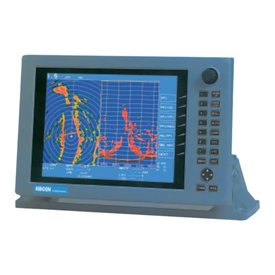
Summary of Contents for Koden MRE-280
- Page 1 OPERATION MANUAL KODEN ELECTRONICS CO.,LTD. ATA (Automatic Tracking Aid) 13-24, TAMAGAWA 2-CHOME, OTA-KU TOKYO 146-0095 JAPAN TEL : +81 3 3756 6918 MRE-280 FAX : +81 3 3756 6831 http://www.koden-electronics.co.jp/ PRINTED IN JAPAN 93144222-02...
- Page 2 No part of this publication may be reproduced, transmitted, translated in any form by any means without the written permission of Koden Electronics Co., Ltd. The technical descriptions contained in this publication are subject to change without notice. KODEN assumes no responsibility for any errors, incidentals or consequential damages caused by misinterpretation of the descriptions contained in this publication.
-
Page 3: Table Of Contents
MRE-280 Contents Operation Manual Contents Page No. General..................1 Precautions....................1 Specifications................. 1 Installing ATA................2 Applicable radar models ................2 Installing ATA PCB ..................2 Operation ................5 Setting the ATA parameters ..............5 Changing the acquisition mode ..............5 Operating procedures ................ -
Page 4: General
Operation Manual 1. General The Automatic Tracking Aid (ATA, herein after) MRE-280 is a built-in type optional adaptor unit developed for KODEN marine radar sets. The ATA predicts the motion of the selected targets by processing the radar video signal supplied from the radar set. Up to ten targets can be acquired manually or automatically and tracked automatically. -
Page 5: Installing Ata
MRE-280 Operation Manual NOTE: The MRE-280 does not accept bearing signals other than those specified above. In case the ATA board is used in the monitor display, make sure that the data rate of an incoming bearing signal supplied form the antenna agrees with that specified in this specification. - Page 6 MRE-280 Descriptions Operation Manual (PCB connections on the backside of the display front panel) Figure 1 Installing MRE-280 into the display 93144222-01...
- Page 7 Table 1 Composition of MRE-280 Item name Type Q’ty ATA board E35-7010 Screw assembly PWSM3X6B Cable harness E35ELA3000 Table 2 Parts list of MRE-280 assembly Item name Parts code Type Q’ty Front panel Rear panel chassis Tapping screw Not specified BDT4X16U...
-
Page 8: Operation
MRE-280 Descriptions Operation Manual 4. Operation 4.1 Setting the ATA parameters Before using the ATA function, the following ATA parameters must be set. CPA: Closest point of approach. Enter the minimum distance of other ship’s approach. Unit in NM. Default: 3.0 NM. -
Page 9: Operating Procedures
S1-3: OFF, S1-4: OFF 4.3 Operating procedures 4.3.1 Acquisition of a target There are two acquisition modes available in the MRE-280, i.e. manual acquisition and auto acquisition. Use the following procedures to operate. 4.3.1.1 Manual acquisition (1) Place the cursor on the target to be tracked and acquire it using the ACQ (acquisition) function. -
Page 10: Tracking A Target
MRE-280 Descriptions Operation Manual screen. A vacant row with a “-“ indicates no target has been acquired. 4.3.2 Tracking a target As soon as a stable tracking is established, the target is circled with the tracking symbol and a vector is created from the target. -
Page 11: Ship's Speed Setting
Descriptions MRE-280 Operation Manual The display items are as follows: Target number: TGT NO.x The number of the target currently displayed. Vector time: TIME x x MIN. Setting time to display vector length. (Speed x Time = vector length) Vector mode: TRUE or REL Display mode of vector data. -
Page 12: Interface
MRE-280 Descriptions Operation Manual 5. Interface 5.1 Data output The ATA data output is available at the optional connector terminal on the rear of the display unit. Pin No.32 is the NMEA_OUT signal terminal from which the signals conforming to the NMEA 0183 protocol can be output.


Need help?
Do you have a question about the MRE-280 and is the answer not in the manual?
Questions and answers