Table of Contents
Advertisement
Quick Links
Advertisement
Chapters
Table of Contents

Related Manuals for Koden KGP-925


Summary of Contents for Koden KGP-925
- Page 2 No part of this publication may be reproduced, transmitted, translated in any form by any means without the written permission of Koden Electronics Co., Ltd. The technical descriptions contained in this publication are subject to change without notice. Koden assumes no responsibility for any errors, incidentals or consequential damages caused by misinterpretation of the descriptions contained in this publication.
- Page 3 KGP-925 Preface Safety Precautions Disconnect Main Power It is still possible to receive an electric shock caused by unintentionally switching on the power during repair work. To prevent this from happening, make sure to completely disconnect the unit from the ship’s main supply before attempting any inspection and repair.
- Page 4 Preface KGP-925 Symbols used in this manual The following symbols are used in this manual. You are requested to be fully aware of the meaning of each symbol before carrying out inspection and maintenance of this equipment. Alarm mark To handle the equipment ignoring this sign may lead to injury to the human body or damage to the equipment.
-
Page 5: About Gps And Glonass
Preface How to use this manual Scope of this manual This manual contains information about installation, operation and maintenance of the KGP-925 GPS/GLONASS navigator. Structure of this manual This manual is divided into sections according to the contents as described below. This arrangement will help you overview the whole contents as well as refer to detailed information for your specific requirement. - Page 6 Preface KGP-925 Chapter 5 : Basic Operation The name and function of each part Power On/Off Adjusting display contrast and brightness Selecting the screen Storing present position (EVENT) Using MOB (Man over-board) key Recalling event or MOB position Displaying average speed, average bearing and elapsed time...
- Page 7 KGP-925 Preface Chapter 10: Maintenance and Troubleshooting Periodic inspection and cleaning Troubleshooting Chapter 11: Technical Reference Digital interface (IEC 61162-1 Ed.4) Chapter 12: Communication with external navigation system Changing to the EXTERNAL mode Route data transfer Annex Menu Tree DGNSS beacon reference stations list...
- Page 8 KGP-925 Chapter 1 General Information Chapter 1 General Information Page No. About GPS and GLONASS..............1-1 1.1.1 General ......................1-1 1.1.2 Positioning by GPS/GLONASS ..............1-1 1.1.3 Time required for position fix................. 1-1 Outline of the equipment.................1-2 Equipment composition ................1-2 Software type name .................1-2 Corresponding with Technical Regulations ..........1-4...
-
Page 9: Positioning By Gps/Glonass
KGP-925 Chapter 1 General Information Chapter 1 General Information 1.1 About GPS and GLONASS 1.1.1 General GPS is a navigation system using 24 satellites (21 plus 3 in service) orbiting 20,183 km high from the earth every 11 hours 58 minutes. And GLONASS is orbiting 19,100 km high from the earth 11 hours 15 minutes. -
Page 10: Outline Of The Equipment
Chapter 1 General Information KGP-925 1.2 Outline of the equipment The KGP-925 of GPS/GLONASS navigator is designed and manufactured to meet the carriage requirement of the latest IMO/SOLAS regulation and its harmonized IMO resolution MSC.115(73) and IEC technical standards, shown below. -
Page 11: Chapter 1 General Information
KGP-925 Chapter 1 General Information *RA-14 is a name in the KODEN Whip antenna Antenna unit BA-03(*RA-14) MA-620G NOTE: Connecting cable is option (Option) Beacon antenna coupler BA-02L-K (Option) Chart plotter Marine radar Echo sounder Auto pilot (Other brand) Chart plotter... - Page 12 The marking can be performed by one of four variants, depending on surface color of equipment. The marking of navigation should be done by the manufacturer (supplier) and should be applied right to device surface.» 1.5.4. « Shipborne combined GPS/GLONASS Receiver Equipment, type «KGP-925» has marking by caution plates in Russian and English.» «HIGH VOLTAGE»...
- Page 13 :89-FZ dated 24.06.98 in the acting edition. Recycling of Shipborne combined GPS/GLONASS Receiver Equipment, type «KGP-925» , accumulator batteries and other equipment should be done only by organizations registered in Assay Chamber and approved for utilization of the defined type of products with mentioning the owner of the waste.
- Page 14 KGP-925 Chapter 2 Equipment Composition Chapter 2 Equipment Composition Page No. Standard equipment list ................2-1 Option items list..................2-1 0093192502-00 Contents...
- Page 15 Whip antenna *BA-03(RA-14) 0.3kg 2.45m, for BA-02 Operation manual KGP-925.OM.E English KGP-925.SM.E Service manual English *About Whip antenna: BA-03 is a name in the MT Electronics LLC, but RA-14 is a name in the KODEN Electronics Co.,Ltd. 0093192502-01...
-
Page 16: Table Of Contents
KGP-925 Chapter 3 Specifications Chapter 3 Specifications Page No. GPS/GLONASS receiver section ............3-1 Beacon receiver section (Internal beacon receiver type only) ....3-1 Display section ..................3-1 Data Input/Output..................3-2 Power requirements ................3-2 Compass safe distance ................3-2 Environmental conditions ...............3-2 External dimensions and weight ............3-3... -
Page 17: Gps/Glonass Receiver Section
KGP-925 Chapter 3 Specifications Chapter 3 Specifications 3.1 GPS/GLONASS receiver section Receiving frequency 1575.42 MHz(GPS) 1597.5 - 1609.5MHz(GLONASS) Receiving channel 32 channel parallel Satellite access mode All-in-view -160dBm(tracking and reacquisition) -143dBm(acquisition) Sensitivity Accuracy Position 2.5m RMS(autonomous), 1m RMS(differential) Velocities 0.1 kt rms Note: Accuracy is subject to change in accordance with DoD civil GPS user policy. -
Page 18: Data Input/Output
Chapter 3 Specifications KGP-925 3.4 Data Input/Output Output data format IEC 61162-1/ NMEA 0183 Ver.1.5 (NMEA1, 2)/ CIF/ SHIPMATE (DATA connector) (AAM, APB, BOD, BWC, DCN, DTM, GBS, GGA, GLC, GLL, GNS, GSA, GSV, MSS, RMB, RMC, Rnn, RTE, SGR, VTG, WDC, WPL, XTE, ZDA) -
Page 19: External Dimensions And Weight
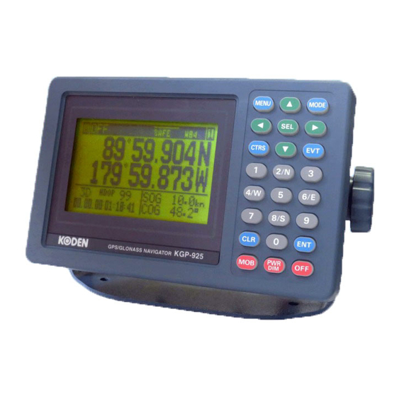
Refer to Figure 3.3 for exterior of antenna unit with dimensions. Refer to Figure 3.4 for exterior of beacon antenna coupler with dimensions. (Internal beacon receiver type only) Unit: mm (inch) Figure 3.1 The Exterior of KGP-925 with dimensions Unit: mm (inch) Figure 3.2 Service space required for KGP-925 0093192502-01... - Page 20 Chapter 3 Specifications KGP-925 Unit: mm (inch) MA-620G: with cable (10m) Weight Without cable : 0.18kg Figure 3.3 The Exterior of antenna unit with dimensions BA-02L-K : with cable (15m) Weight Without cable : 0.4kg Figure 3.4 The Exterior of beacon antenna coupler with dimensions (Option)
- Page 21 4.6.1 Selecting the best site of GPS/GLONASS and beacon antenna units..4-4 4.6.2 Fixing the GPS/GLONASS antenna unit............4-5 4.6.3 Fixing the beacon antenna coupler and receiving antenna (internal beacon receiver type only)..................4-5 Cable connections to KGP-925...............4-6 4.7.1 Single connection.................... 4-6 4.7.2 Multi connections .................... 4-7 Connector pin outs ..................4-8 Inspection after installation ..............4-9...
-
Page 22: Installation Consideration
Chapter 4 Installation 4.1 Installation consideration General Qualified service technicians should perform the installation of the KGP-925 that comprises the following operations. (1) Unpacking each component of the system. (2) Inspection of the exterior of each component unit and accessory. - Page 23 Chapter 4 Installation KGP-925 Figure 4.1 Fitting detail of KGP-925 in table mounting mode Figure 4.2 Service space required for KGP-925 Unit: mm (inch) 0093192502-01...
-
Page 24: Flush Mounting
(4) Put the display on the opening and fix with four (4) tapping screws. In case you use M4 screws to fix the display, select an appropriate screw length that best suits fixing the unit to the panel thickness. Figure 4.3 Fitting KGP-925 in flush mounting mode Unit: mm (inch) 0093192502-01... -
Page 25: Antenna Unit Installation
Chapter 4 Installation KGP-925 4.6 Antenna unit installation 4.6.1 Selecting the best site of GPS / GLONASS and beacon antenna units Make sure to install the antenna unit at a location where nothing shades the antenna of a view above the horizon. -
Page 26: Fixing The Gps/Glonass Antenna Unit
MA-620G Base mounting Roof top Screw (1”-14UNS-2B) Antenna extension pole (not supplied) 4.6.3 Fixing the beacon antenna coupler and receiving antenna (Internal beacon receiver type only) (Case2) (Case1) BA-03(*RA-14) (Option) BA-03(*RA-14) *RA-14 is a name in the KODEN (Option) 0093192502-01... -
Page 27: Cable Connections To Kgp-925
Chapter 4 Installation KGP-925 4.7 Cable connections to KGP-925 4.7.1 Single connection *RA-14 is a name in the KODEN Antenna unit Whip antenna MA-620G BA-03(*RA-14) (Option) Beacon antenna coupler BA-02L-K(Option) Chart plotter Marine radar CW-391-1-5M Echo sounder Auto pilot (Other brand) -
Page 28: Multi Connections
KGP-925 Chapter 4 Installation 4.7.2 Multi connections *RA-14 is a name in the KODEN Whip antenna Antenna unit BA-03(*RA-14) MA-620G (Option) Beacon antenna coupler BA-02L-K(Option) Chart plotter Marine radar CW-391-1-5M Echo sounder Auto pilot (Other brand) CW-376-5M Chart plotter GTD-110/150... -
Page 29: Connector Pin Outs
Chapter 4 Installation KGP-925 4.8 Connector pin outs POWER DATA DATA 2 1: GND/SHIELD 1: DC + 1: GND/SHIELD 2: TXD (+) 2: F.GND 2: TXD (+) 3: TXD (-) 3: DC - 3: TXD (-) 4: RXD (+) 4: RXD (+) -
Page 30: Inspection After Installation
KGP-925 Chapter 4 Installation (DATA port) This port is general data output port. Output data is selected by the menu among the output of IEC 61162-1, NMEA Ver.1.5, CIF, and SHIPMATE. Output signal level is RS-422. (DATA 2 port) When CW-376/391 is used. - Page 31 KGP-925 Chapter 5 Basic Operation Chapter 5 Basic Operation Page No. The name and function of each part ............5-1 5.1.1 Control panel ....................5-1 Power On/Off....................5-2 Adjusting display contrast and brightness ...........5-2 Selecting the screen ................5-3 5.4.1 A (NAV1) screen....................5-3 5.4.2 B (NAV2) screen....................
-
Page 32: The Name And Function Of Each Part
KGP-925 Chapter 5 Basic Operation Chapter 5 Basic Operation 5.1 The name and function of each part 5.1.1 Control panel Cursor shift (Up) Selects NAV1 , NAV2, NAV3 Recalls the menu or PLOT screen. Selects parameters Cursor shift (Left) Cursor shift (Right) -
Page 33: Power On/Off
Chapter 5 Basic Operation KGP-925 5.2 Power On/Off Press to power on. Initial message during power-on. The receiver is performing the self-check. GLONASS F14* Message to indicate checking of GPS receiver and display has been completed. GLONASS F14* Blinking Blinks when NAVIGATOR is searching GPS satellites. -
Page 34: Selecting The Screen
KGP-925 Chapter 5 Basic Operation 5.4 Selecting the screen A (NAV1) screen: Indicates your present position as numerical data. B (NAV2) screen: Displays a bearing circle (with your boat positioned at the graph center). It shows the bearing, course, deviation, distance and cross track error from the waypoint. - Page 35 Chapter 5 Basic Operation KGP-925 (Page 3) Blinks when your position has failed to fix (Velocity made good) Position (Course made good) Elapsed time (Page 4) Your present position • LAT/LONG is displayed, when displaying position data in Loran C, Loran A or Decca LOPs mode.
- Page 36 KGP-925 Chapter 5 Basic Operation 5.4.3 C (NAV3) screen : 3-D Highway mode Page number Speed Course Position Blinks when your position has failed to fix Your boat NAV3 screen shows a 3-dimensional view indicating the distance, course, cross track error, and deviation from the waypoint.
- Page 37 Chapter 5 Basic Operation KGP-925 (Page 4) Close-up of PLOT screen 0093192502-00...
-
Page 38: Auto
KGP-925 Chapter 5 Basic Operation 5.5 Storing present position (EVENT) You can store up to 199 present positions with numbers 001 to 199. When you store additional positions, the oldest position is deleted and the newest position is stored in its place. -
Page 39: Using Mob (Man Over-Board) Key
Chapter 5 Basic Operation KGP-925 Symbol list New symbol 5.6 Using MOB (Man over-board) key MOB function is provided for an emergency situation (if a person falls into the water) to make it easier to return to MOB point. CAUTION... -
Page 40: Recalling Event Or Mob Position
KGP-925 Chapter 5 Basic Operation (Page 2) Press [SEL] key when changing a page. Antenna height Present Date (Month, Day, Year) Present time (Greenwich or local time) The elapsed time (mm:ss) after you pressed MOB key NOTE: The time display that is shown when the elapsed time has exceeded 99 minutes 59 seconds after the MOB key was pressed. -
Page 41: Displaying Average Speed, Average Bearing And Elapsed Time
Chapter 5 Basic Operation KGP-925 LAT/LONG mode (Example) Storage number Data displayed when you press MOB key Symbol (O:Fixed), storage date, storage time Storage position Data displayed when you press EVT key Symbol, storage date, storage time Storage position 5.8 Displaying average speed, average bearing and elapsed time (1) Press [MODE] key until A (NAV1) screen appears. - Page 42 KGP-925 Chapter 6 Various Navigation Chapter 6 Various Navigation Page No. Storing waypoint (LAT/LONG) data ............6-1 6.1.1 Storing a new position or updating an existing one ........6-1 6.1.2 Writing comment ..................... 6-1 6.1.3 Copying a position ..................6-2 6.1.4 Changing comment I.D................... 6-3 6.1.5 Erasing a single waypoint ................
- Page 43 KGP-925 Chapter 6 Various Navigation Setting an anchor position ..............6-18 6.6.1 Storing an anchor position ................6-18 6.6.2 Recalling anchor position................6-18 6.6.3 Removing the anchor position symbol on PLOT screen ......6-19 6.6.4 Reentering an anchor position..............6-19 6.6.5 Canceling anchor position................6-19 6.6.6 B (NAV2) screen during anchor position setup ..........6-20...
-
Page 44: Storing A New Position Or Updating An Existing One
KGP-925 Chapter 6 Various Navigation Chapter 6 Various Navigation 6.1 Storing waypoints (LAT/LONG) data NOTE: Press to backspace the NOTE: Press to clear incorrect cursor to correct an input Input. You can reenter error. Numeric data. 6.1.1 Storing a new position or updating an existing one Up to 200 waypoints can be stored in memory. -
Page 45: Copying A Position
Chapter 6 Various Navigation KGP-925 (9) Press [ENT] key and decide of a comment. Example of symbols: : Reference point : Fishing spot : Shallow : Sunken ships : Buoy : Anchoring point or other ships : Prohibited area : Fish gathering place... -
Page 46: Changing Comment I.d
KGP-925 Chapter 6 Various Navigation 6.1.4 Changing comment I.D. You can change a comment stored in memory. (1) Press [MENU] key until Menu options 1 to 9 appears. (2) Press [1] key to select “1:WAYPOINT”. (3) Enter storage number (001 to 399) using numeric keys. -
Page 47: Setup Of Waypoint Navigation
Chapter 6 Various Navigation KGP-925 6.2 Setup of waypoint navigation NOTE: Press to backspace the NOTE: Press to clear incorrect cursor to correct an input Input. You can reenter error. Numeric data. 6.2.1 Setting waypoint navigation The position data for each waypoint must be set prior to navigating to waypoints. You can use the data already stored from Menu, or you can set the waypoints on A (NAV1), B (NAV2), C (NAV3) or D (PLOT) screen (called the quick waypoint navigation). -
Page 48: Reentering The Starting Point In Waypoint Navigation
KGP-925 Chapter 6 Various Navigation 6.2.3 Reentering the starting point in waypoint navigation Once reset, the present position is used as the new point of origin for waypoint navigation. While the 1st to 4th pages of either the A (NAV 1), B (NAV 2), C (NAV 3) or D (PLOT), are displayed. -
Page 49: C (Nav3) Screen During Waypoint Navigation
Chapter 6 Various Navigation KGP-925 6.2.6 C (NAV3) screen during waypoint navigation NOTE: To change a display page: Press this key WPT number Page number Page number Cross track error Speed Deviation angle Course WPT position Present position XTE alarm range... -
Page 50: Cross Track Error And Course Deviation Angle
KGP-925 Chapter 6 Various Navigation 6.3 Cross track error and course deviation angle 6.3.1 Navigation graph of (NAV2) screen Use the navigation graph to check the distance and bearing to the waypoint. When the distance to WPT is further than the range (radius) of navigation graph, the WPT locates on the circle of navigation graph. -
Page 51: Electronic Fairway (Nav3) Screen
Chapter 6 Various Navigation KGP-925 6.3.2 Electronic fairway (NAV3) screen Use the three-dimensional chart for navigation on the course line. You can set a course width from Menu (6: Alarm). Symbol “ ” shows the waypoint, and your ship and track are shown along the course line. - Page 52 KGP-925 Chapter 6 Various Navigation (Nearing to the WPT ) When you close to the waypoint, the course line length decreases to 4 (nm, sm, km), 2 (nm, sm, km) and 1 (nm, sm, km). Then, the WPT marking closes to your ship.
-
Page 53: Storing And Erasing Routes
Chapter 6 Various Navigation KGP-925 6.4 Storing and erasing routes NOTE: Press to backspace the NOTE: Press to clear incorrect cursor to correct an input Input. You can reenter error. Numeric data. 6.4.1 Storing your route • Up to 20routes and 230 waypoints can be registered for one route. -
Page 54: Automatic Switching Of Waypoints
KGP-925 Chapter 6 Various Navigation 6.4.2 Automatic switching of waypoints Route navigation can switch the current waypoint in two ways: switching in CIRCLE mode and switching in BI-SECTOR mode. In CIRCLE mode, the next waypoint is shown when you reach the proximity alarm circle. -
Page 55: Erasing A Single Route
Chapter 6 Various Navigation KGP-925 6.4.4 Erasing a single route (1) Press [MENU] key until Menu options 1 to 9 appears. (2) Press [2] key to select “2: ROUTE”. (3) Press [1] key to select “1: ROUTE EDIT”. Route Input screen is displayed. -
Page 56: Route Setup
KGP-925 Chapter 6 Various Navigation 6.5 Route setup You can use up to 400 points (maximum) to go to a final destination using route navigation. You can also reverse the navigation route to return to the start point. To do so, you must first store the waypoints and route from Menu (using option 2). -
Page 57: Checking A Route Point Position
Chapter 6 Various Navigation KGP-925 6.5.3 Checking a route point position You can check the waypoints on a route from the Menu. (1) Press [MENU] key until Menu options 1 to 9 appears. (2) Press [2] key to select “2: ROUTE”. -
Page 58: Switching Between Distance And Time To Go
KGP-925 Chapter 6 Various Navigation 6.5.6 Switching between distance and time to go When you select the “RNG” (Distance to WPT) or “TRNG” (Total distance) on NAV1, NAV2 or NAV3 screen in route navigation, the respective “TTG” (Time to go to WPT) or “T.TTG” (Total time to go) is shown. -
Page 59: B (Nav2) Screen During Route Navigation
Chapter 6 Various Navigation KGP-925 6.5.7 B (NAV2) screen during route navigation NOTE: To change a display page: NOTE: Positioning has failed or the distance Press this key has exceeded 9999 nm, sm or km. RNG: 9999 Forward (→) or backward (←) navigation... -
Page 60: D (Plot) Screen During Route Navigation
KGP-925 Chapter 6 Various Navigation 6.5.9 D (PLOT) screen during route navigation Page number NOTE: To change a display page: Distance to the next Press this key Route point Bearing to the next For description of the parameters shown in... -
Page 61: Setting An Anchor Position
Chapter 6 Various Navigation KGP-925 6.6 Setting an anchor position After arriving at your destination, it is possible to drift from the anchor position due to a tide or wind. Once the anchor position is stored in memory, it is easy to check the distance and bearing moved from the anchor position. -
Page 62: Removing The Anchor Position Symbol On Plot Screen
KGP-925 Chapter 6 Various Navigation 6.6.3 Removing the anchor position symbol on PLOT screen You can remove the anchor position as a symbol on the PLOT screen. (1) Press [MODE] key until D (PLOT) screen appears. (2) Press [SEL] key until page 6 screen appears. -
Page 63: B (Nav2) Screen During Anchor Position Setup
Chapter 6 Various Navigation KGP-925 6.6.6 B (NAV2) screen during anchor position setup Page number Page number Distance from Time to go from present position to present position to anchor position anchor position Bearing from Arrival time present position to... -
Page 64: Track Display
KGP-925 Chapter 6 Various Navigation 6.7 Track display You can display track, the waypoint, course line, and cross cursor on the PLOT screen. 6.7.1 Display a cross cursor on PLOT screen You can display a cross cursor and position it on the screen. -
Page 65: Scaling The Plot Screen
Chapter 6 Various Navigation KGP-925 6.7.3 Scaling the PLOT screen Initial scale: 0.025 You can select a display scale of PLOT (pages: 1, 2, 4) screen. (1) Press to [ ] or [ ] key to select a desired range. - Page 66 KGP-925 Chapter 6 Various Navigation (Adjusting the track recording interval) To adjust the track recording interval (time or distance interval), locate cursor on PLOT option, and press ENT key. You can set the unit of track distance interval from the Menu 2: UNIT (RNG) of 8 INITIAL.
- Page 67 KGP-925 Chapter 7 Alarms Chapter 7 Alarms Page No. Kinds of alarms..................7-1 7.1.1 Anchor watch alarm (ANCH) ................7-1 7.1.2 Proximity alarm (PROX) .................. 7-1 7.1.3 Cross track error alarm (XTE) ................ 7-2 7.1.4 Course deviation angle alarm (CDI)............... 7-2 Alarm explanation..................7-2...
-
Page 68: Kinds Of Alarms
KGP-925 Chapter 7 Alarms Chapter 7 Alarms 7.1 Kinds of alarms There are four kinds of alarms, anchor watch (ANCH), proximity (PROX), cross track error (XTE) and course deviation angle. 7.1.1 Anchor watch alarm (ANCH) An anchor watch alarm can alert you if your boat drifts a set distance from where it is activated. This alarm function will not work if the alarm range is set to "0.00". -
Page 69: Cross Track Error Alarm (Xte)
Chapter 7 Alarms KGP-925 7.1.3 Cross track error alarm (XTE) The cross track error (XTE) alarm alerts you when you have deviated from your course line by a predetermined distance. The alarm function does not work if the alarm range is set to '0.00'. The course width shown on NAV3 screen is the same as the XTE alarm value you have set. -
Page 70: Setting And Canceling
KGP-925 Chapter 7 Alarms 7.3 Setting and canceling (Setting alarm) (1) Press [MENU] key until Menu options 1 to 9 appears. (2) Press [6] key to select “6: ALARM”. (3) Select item number of the alarm to be set from the numerical keypad. - Page 71 KGP-925 Chapter 8 Setup Procedure Chapter 8 Setup Procedure Page No. Menu options ...................8-1 Menu 3: GNSS ..................8-2 8.2.1 Monitoring GPNS satellite signal reception..........8-2 8.2.2 Selecting a GNSS mode.................. 8-2 8.2.3 Selecting a geodetic datum ................8-2 8.2.4 Masking S/N of satellites ................8-3 8.2.5 Masking satellite elevation angle..............
- Page 72 Chapter 8 Setup Procedure KGP-925 8.5.7 Specifying the chain and secondary stations for Loran C, Loran A or Decca ..........................8-15 Menu 9: Interface................... 8-16 8.6.1 Selecting an output data format of DATA port ..........8-16 8.6.2 Editing the IEC 61162-1 output data format of DATA port ......8-16 8.6.3 Explanation of output data (sentence)............8-17...
-
Page 73: Menu Options
KGP-925 Chapter 8 Setup Procedure Chapter 8 Setup Procedure 8.1 Menu options NOTE : You can select an option from Menu in two ways: by direct numeric key entry and by cursor shifting. This manual explains how to enter numeric values for easy understanding, but you can also use the cursor for option selection. -
Page 74: Menu 3: Gnss
The latitude and longitude of GPS system are calculated based on the WGS-84, and GLONASS system is calculated based on the PZ-90. The KGP-925 has been equipped 4 geodetic datum. You can select one geodetic datum from WGS-84, PZ-90, SK-42, or SK-95. -
Page 75: Masking S/N Of Satellites
KGP-925 Chapter 8 Setup Procedure Cursor 8.2.4 Masking S/N of satellites Initial setup: 30 When used satellites of low S/N in navigation calculations, the accuracy of speed, course, and position may often deteriorate. Therefore moderate masking S/N of satellites is necessary. However, attention is necessary for the large mask value shortens the signal receive time. -
Page 76: Selecting Raim Accuracy
Chapter 8 Setup Procedure KGP-925 RAIM accuracy ( ) or ( Status 1.SAFE: GPS signal is safe to use 2.CAUTION Using a GPS signal, necessity or a RAIM function does not have enough cautions. 3.GPS signal is unsafe to use. -
Page 77: Menu 4: Differential Gnss (Dgnss)
8.3.3 Selecting a beacon station Initial setup: AUTO A beacon station is selectable in both the manual or auto mode. KGP-925 outputs MSK sentence and position data to an external beacon receiver. If connect a beacon receiver supporting MSK sentence, you can automatically select optimum reference station when selected auto mode, The manual mode differs by the External beacon receiver type and Internal beacon receiver type. - Page 78 Chapter 8 Setup Procedure KGP-925 (3) Press [ ] or [ ] key to move cursor onto “NEXT” and 2/2 page is displayed. (4) Press [1] key to select “1: STN SEL”. (5) Press [ ] or [ ] key to move cursor onto “AUTO”.
-
Page 79: Storing A Beacon Station (Internal Beacon Receiver Type Only)
KGP-925 Chapter 8 Setup Procedure (Selecting a station in the manual mode by internal beacon receiver type) In the manual mode of internal beacon receiver system, specify the station number between 001 and 999. (Refer “Table of DGPS reference stations” of supplement.) (1) Press [MENU] key until Menu options 1 to 9 appears. -
Page 80: Selecting The Dgnss Input Signal Baud Rate (External Beacon Receiver Type Only)
Chapter 8 Setup Procedure KGP-925 (9) Press [ ] key to move cursor to the station number field. (10) Enter station number (001 to 020) by numerical keys. (11) Press [ENT] key. (12) Press [ ] key to move cursor to the frequency input field. -
Page 81: Dgnss Monitor
KGP-925 Chapter 8 Setup Procedure 8.3.6 DGNSS monitor DGNSS monitor provides information on the DGPS beacon receiver interface and receiving status. (1) Press [MENU] key until Menu options 1 to 9 appears. (2) Press [4] key to select “4: DGNSS”. -
Page 82: Menu 5: Compensation
Chapter 8 Setup Procedure KGP-925 8.4 Menu 5: Compensation 8.4.1 Correcting your position You can compensate your GNSS present position given by GNSS in the following two ways: • Enter the latitude and longitude of your actual position using numeric keys. -
Page 83: Checking The Correction Offset
KGP-925 Chapter 8 Setup Procedure NOTE: Press to clear incorrect Input. You can reenter Numeric data. Present position Corrected position Cursor Correction amount Correction offset (to be entered) Present position Correction position Latitude 00.193 S Latitude 37.893 N Latitude 37.700 N Longitude 0 00.148 W... - Page 84 Chapter 8 Setup Procedure KGP-925 (Manual compensation) initial setup: 0.0 Setup range: -180.0° to +180.0° (1) Press [MENU] key until Menu options 1 to 9 appears. (2) Press [5] key to select “5: COMP.”. (3) Press [3] key to select “3: MAG.V”.
-
Page 85: Displaying Local Time
KGP-925 Chapter 8 Setup Procedure 8.4.5 Displaying local time Initial setup: 00:00 hour You can display your local time by entering a time difference from the Universal Time Coordinated (UTC). See the following figure 8.1 to determine zone time difference. -
Page 86: Menu 8: Initial Setting
Chapter 8 Setup Procedure KGP-925 8.5 Menu 8: Initial setting 8.5.1 Setting average constants(speed and course) Initial setup: 0 Use the averaging function to compare GPS sensor signals several times and get their average. This stabilizes the speed and course data. The maximum averaging rate is “3” and the minimum averaging rate is “0”. -
Page 87: Changing Sail Mode
KGP-925 Chapter 8 Setup Procedure 8.5.4 Changing sail mode Initial setup: GREAT CIRCLE You can change the navigation mode. There are two navigation modes. Great Circle course: ..The shortest course on a sphere. Rhumb Line course: ..Straight course on a Mercator chart. -
Page 88: Menu 9: Interface
Chapter 8 Setup Procedure KGP-925 8.6 Menu 9: Interface 8.6.1 Selecting an output data format of DATA port . Initial setup: IEC DATA port You can select the format of output data. (1) Press [MENU] key until Menu options 1 to 9 appears. -
Page 89: Explanation Of Output Data (Sentence)
KGP-925 Chapter 8 Setup Procedure 8.6.3 Explanation of output data (sentence) Waypoint Arrival Alarm Autopilot Sentence "B" (Bearing from origin or present position to the waypoint) Bearing - Point of Origin to Destination Bearing & Distance to Waypoint in Great Circuit navigation... -
Page 90: Selecting An Output Data Format Of Data 2 Port
Chapter 8 Setup Procedure KGP-925 8.6.5 Selecting an output data format of DATA 2 port . Initial setup: Extension data port You can select either the extension data port or exclusive port of ACK/ALARM for DATA 2 port. It can select ACK/ ALARM of a menu3 in turning on or turning off. If ACK/ ALARM is turned ON, it will be set to exclusive port of ACK/ ALARM, and it will be set to extension data port if it turns OFF. -
Page 91: Initialization
KGP-925 Chapter 8 Setup Procedure 8.7 Initialization (Displaying the menu) Turn power on, then press the ENT key while the screen message "CHECK OK" is displayed. (How to use menus) Initialization 1) Press [1] key to select “1: INITIALIZE”. 2) Press [ENT] key. Menu is initialized and the screen for powering off will appear. -
Page 92: Selecting An Initial Value (North, South, East, West) Of Latitude/Longitude
Chapter 8 Setup Procedure KGP-925 MANUAL: Press the EVT key, then specify desired registration numbers (in the range of 001 to 199) from the numerical keypad. In the MANUAL mode, you can specify desired registration numbers 8.7.5 Selecting an initial value (North, South, East, West) of latitude/longitude Initial setup: N/W N/W (N. - Page 93 KGP-925 Chapter 9 How to use LOPs Chapter 9 How to use LOPs Page No. Initial setup for LOPs display ..............9-1 9.1.1 Selecting LOP (Loran C, Loran A or Decca)..........9-1 9.1.2 Setting the chain and secondary stations to be displayed ......9-1 9.1.3 Registering a position in LOPs ..............
-
Page 94: Initial Setup For Lops Display
KGP-925 Chapter 9 How to use LOPs Chapter 9 How to use LOPs 9.1 Initial setup for LOPs display Measured longitude and latitude can be translated into loran C, loran A or decca LOPs mode. To turn on the LOPs mode, the following initial setup is required. - Page 95 Chapter 9 How to use LOPs KGP-925 (7) Press [ ] key. (8) Press [ENT] key. (9) Press [ ] or [ ] key to select the secondary station 2. (10) Press [ENT] key. Cursor Secondary station 1 Secondary station 2...
-
Page 96: Registering A Position In Lops
KGP-925 Chapter 9 How to use LOPs 9.1.3 Registering a position in LOPs Following describes the procedure for replacing LAT/LONG display with LOP and registering a position in LOP (1) Press [MENU] key until Menu options 1 to 9 appears. -
Page 97: Storing Waypoints (Lops Data)
Chapter 9 How to use LOPs KGP-925 9.2 Storing waypoints (LOPs data) NOTE: Press to backspace the NOTE: Press to clear incorrect cursor to correct an input Input. You can reenter error. Numeric data. 9.2.1 Storing a new position or updating an existing one Up to 200 waypoints can be stored in memory. -
Page 98: Correcting Your Position (Lops)
KGP-925 Chapter 9 How to use LOPs 9.3 Correcting your position (LOPs) You can compensate your GPS present position given by GPS in the following two ways: • Enter the LOPs of your actual position using numeric keys. • Enter the correction offset to use. - Page 99 Chapter 9 How to use LOPs KGP-925 (5) Press [ENT] key. (6) Press [ ] key to move cursor to Loran A LOPs field of secondary station 2. (7) Enter correct (5-digit) LOPs of secondary station 2 using numeric keys.
-
Page 100: Entry Of Correction Offset
KGP-925 Chapter 9 How to use LOPs 9.3.2 Entry of correction offset (Correction by Loran C LOPs data entry) When your position is displayed in Loran C LOPs mode, you can correct it by entering the Loran C LOPs correction offset. - Page 101 Chapter 9 How to use LOPs KGP-925 (7) Press [ENT] key. (8) Press [ ] key to move cursor to correction offset field of secondary station 2. (9) Press [SEL] key to change the positive (+) or negative (-) sign of correction offset.
-
Page 102: Checking The Correction Offset
KGP-925 Chapter 9 How to use LOPs Actual position (to be entered) Present position Correction position Present position (GPS fix) Correction offset Actual position (to be entered) Secondary st.1 0G:30:62 μsec Secondary st.1 –00:20 μsec Secondary st.1 0G:30:42 μsec Secondary st.2 0C:76:16 μsec Secondary st.2 +00:19 μsec... -
Page 103: Calculating Lops Based On Lat/Long Data
Chapter 9 How to use LOPs KGP-925 9.4 Calculating LOPs based on LAT/LONG data 9.4.1 Calculating Loran C LOPs based on LAT/LONG data You can enter a Loran C chain number and the first digit of two secondary stations, NAVIGATOR calculates the Loran C LOPs based on the specified LAT/LONG data and displays the LOP values. -
Page 104: Calculating Loran A Lops Based On Lat/Long Data
KGP-925 Chapter 9 How to use LOPs 9.4.2 Calculating Loran A LOPs based on LAT/LONG data When You enter a combination of two secondary stations of Loran A, NAVIGATOR calculates the Loran A LOPs based on the specified LAT/LONG data and displays the LOP values. -
Page 105: Calculating Decca Lops Based On Lat/Long Data
Chapter 9 How to use LOPs KGP-925 CAUTION Do not use the converted LOPs position data for waypoint or route navigation because of likely conversion errors. Accuracy of converted positions can be off 1/4 mile or more. 9.4.3 Calculating Decca LOPs based on LAT/LONG data When you enter a Decca chain number and a combination of two secondary stations, NAVIGATOR calculates the Decca LOPs based on the specified LAT/LONG data and displays the LOP values. - Page 106 KGP-925 Chapter 9 How to use LOPs Data currently stored Specified data number ( “X L/L-LOP” : fixed) CAUTION Do not use the converted LOPs position data for waypoint or route navigation because of likely conversion errors. Accuracy of converted positions can be off 1/4 mile or more.
- Page 107 KGP-925 Chapter 10 Maintenance and Troubleshooting Chapter 10 Maintenance and Troubleshooting Page No. 10.1 Periodic inspection and cleaning ............10-1 10.1.1 Monthly check....................10-1 10.1.2 Maintenance....................10-1 10.2 Troubleshooting..................10-1 10.2.1 Information required for service ..............10-1 10.2.2 Troubleshooting ..................10-1 10.2.3 Error message ..................... 10-3...
- Page 108 KGP-925 Chapter 10 Maintenance and Troubleshooting Chapter 10 Maintenance and troubleshooting 10.1 Periodic inspection and cleaning 10.1.1 Monthly check Check if there is any loose connection on the Processor unit for GNSS Antenna, radar or navigational unit. 10.1.2 Maintenance If the Processor unit is smeared or stained with dirt, wipe the surface of the unit with soft dry cloth.
- Page 109 Chapter 10 Maintenance and Troubleshooting KGP-925 Faults detected Possible cause of the failure Remedial action Unstable signal reception 1. Are the connections between the 1. Check the connection and antenna unit and the display unit reconnect, if necessary. is correct and firm? 2.
- Page 110 KGP-925 Chapter 10 Maintenance and Troubleshooting 1. GNSS NO FIX GNSS NO FIX This message is that it became impossible to receive a 37.893N GNSS signal, and when the positioning of it becomes 05.719E impossible, it appears. 01.16.04 06:01:16 Please check whether the connector of an antenna cable has separated, or the cable is not disconnected.
- Page 111 KGP-925 Chapter 11 Technical Reference Chapter 11 Technical Reference Page No. 11.1 Digital interface (IEC 61162-1 Ed.4) ............11-1 11.1.1 Input data format (DATA 2 port)..............11-1 11.1.2 Output data format (DATA / DATA 2 port) ..........11-1 11.1.3 Output data specification................11-1 11.1.4 Output sentence ..................
- Page 112 KGP-925 Chapter 11 Technical Reference Chapter 11 Technical Reference 11.1 Digital Interface (IEC 61162-1 Ed.4) 11.1.1 Input data format (DATA 2 port) RTCM SC104 Ver.2.0 (DGNSS) 11.1.2 Output data format (DATA / DATA 2 port) Data per one byte is as follows:...
- Page 113 Chapter 11 Technical Reference KGP-925 Description Contents of data field GPAPB Heading / Track controller (auto pilot) sentence B $ GP APB, A, A, x.x, a, N, A, A, x.x, a, c--c, x.x, a, x.x, a, a*hh<CR><LF> Mode indicator A: Autonomous...
- Page 114 KGP-925 Chapter 11 Technical Reference Description Contents of data field GPBWC Bearing and distance to waypoint $ GP BWC, hhmmss.ss, llll.lll, a, yyyyy.yyy, a, x.x, T, x.x, M, xx, N, c--c, a*hh<CR><LF> Mode indicator A: Autonomous D: Differential M: Manual input...
- Page 115 Chapter 11 Technical Reference KGP-925 Description Contents of data field GxGBS GPS satellite fault detection GNSS System ID GNSS Signal ID $ Gx GBS, hhmmss.ss, x.x, x.x, x.x, x.x, x.x, x.x, x.x, h, h*hh<CR><LF> Standard deviation of bias estimate Estimate of bias on most likely failed satellite...
- Page 116 KGP-925 Chapter 11 Technical Reference Description Contents of data field GPGLL Geographic position (latitude/longitude) $ GP GLL, lllll.lll, a, yyyyy.yyy, a, hhmmss.ss, A, a*hh <CR><LF> Longitude Latitude, Mode indicator A: Autonomous Sentence type D: Differential Talker device M: Manual input...
- Page 117 Chapter 11 Technical Reference KGP-925 Description Contents of data field GxGSV GNSS Satellite in view GNSS Signal ID $ Gx GSV, x, x, xx, xx, xx, xxx, xx, …………., xx, xx, xxx, xx, h*hh <CR><LF> “2nd and 3 SNR (C/No) 00-99 dB Hz, null when not tracking Azimuth, degrees true, (000 to 359) Elevation, degrees, 90°maximum...
- Page 118 KGP-925 Chapter 11 Technical Reference Description Contents of data field GPRMC Recommended minimum specific GPS data Navigational status indicator $ GP RMC, hhmmss.ss, A, lllll.lll, a, yyyyy.yyy, a, x.x, x.x, xxxxxx, x.x, a, a, a*hh <CR><LF> Mode indicator A: Autonomous...
- Page 119 Chapter 11 Technical Reference KGP-925 Description Contents of data field GPWPL Waypoint location *A maximum of four Waypoints are outputted. $ GP WPL, llll.lll, a, yyyyy.yyy, a, c--c*hh <CR><LF> Waypoint identifier Waypoint latitude, E/W Waypoint latitude, N/S Sentence type Talker device...
- Page 120 KGP-925 Chapter 11 Technical Reference (DATA port output circuit) Device: Driver IC AM26C311 (T.I) +Vcc AM26C31I TXD (+) TXD (- ) (DATA 2 port input circuit) Input load: 470 / 2.4k ohm Device: Photo-coupler TLP181(Toshiba) +Vcc TLP-181 RXD (+) RXD (-) +Vcc 2.4k...
- Page 121 Chapter 11 Technical Reference KGP-925 DATA 2 port output circuit Device: Transistor 2SC2712 EXT BUZZER 2SC2712 11-10 0093192502-00...
- Page 122 KGP-925 Chapter 12 Communication with external navigation system Chapter 12 Communication with external navigation system Page No. 12.1 Changing to the EXTERNAL mode............12-1 12.2 Route data transfer ................12-2 12.2.1 Complete route transfer................12-2 12.2.2 Selecting route navigation................12-3 12.2.3 Working(active) route transfer ..............12-3 12.2.4 Error message .....................
-
Page 123: Changing To The External Mode
(6) Press [ENT] key. Cursor A small E is displayed at the end of the waypoint identifier to show KGP-925 is in external mode. Route identifier shows maximum leading 5 characters of the original route name while waypoint identifier shows maximum leading 6 characters of the original waypoint name. -
Page 124: Route Data Transfer
Maximum waypoint storage capacity is for 400 points combined with both NORMAL and EXT. modes. 12.2.1 Complete route transfer When KGP-925 receives a Complete route data, “OVERWRITING last sent route” is indicated and then it indicates “LOADED ext. route” to notify the route was successfully transferred. -
Page 125: Selecting Route Navigation
12.2.3 Working (active) route transfer When KGP-925 receives Working route data for the first time, it shows “LOADED ext. active route” and goes into Working route mode regardless of previous navigation mode due to the first priority. As far as KGP-925 receives Working route data within 10 seconds consecutively, it continues to work for the received working route. -
Page 126: Error Message
Chapter 12 Communication with external navigation system KGP-925 Following is an example of Working route data. Refer to IEC61162-1 for detail. Max. character number in a line is 124 bytes including w: Working route *Max. number of character is same as Complete route... - Page 127 KGP-925 Annex Annex Page No. Menu Tree......................A-1 DGNSS beacon reference stations list ............A-3 Decca zone....................... A-15 0093192502-01 Contents...
- Page 128 KGP-925 Menu Tree [MENU] key ----- 1:WAYPOINT ----- 2:ROUTE ----- -----1:ROUTE EDIT -----2:WPT CHANGE (CIRCLE, BISECTOR ) -----3:WPT DATA ----- 3:GNSS ------ -----1:GNSS MONITOR -----2:GNSS MODE (GPS+GLN, GPS, GLON ASS, GNSS+SBAS, GPS+SBAS) -----3:DATUM (WGS-84, PZ-90, SK-42, SK-95) -----4:S/N MASK (30, 15, 20, 25, 35) -----5:ELV.MASK (5, 0, 3, 10, 15)
- Page 129 Menu Tree KGP-925 ----- 7:CALCULATE --- -----1:2 POINT -----2:L/L LOP -----3:NAVIGATION PLAN -----1:AVERAGE (0, 1, 2, 3) ----- 8:INIT.SET -------- -----2:UNIT (RNG)(nm, km, sm) -----3:UNIT (ALT)(ft, m) -----4:SAIL MODE (GREAT CIR, MERCATOR) -----5:POSITION (L/L, LOP) -----6:L/L UNIT (.001, .0001) -----7:CHAIN -----8:WPT.ROUTE (NORM, EXT.)
- Page 130 KGP-925 DGNSS beacon reference stations list Freq Country Station name Latitude Longitude rate 031 JAPAN Tsurugizaki 35°08'N 139°41'E Daiozaki 34°17'N 136°54'E Kinkazan 38°17'N 141°35'E Inubousaki 35°42'N 140°52'E Hachijoujima 33°05'N 139°51'E Murotomisaki 33°15'N 134°11'E Toimisaki 31°22'N 131°20'E Oosesaki 32°37'N 128°36'E Wakamiya 33°52'N...
- Page 131 DGNSS beacon reference stations list KGP-925 228 FINLAND Marjaniemi 65°02'N 024°35'E 314.5 Kuopio 63°00'N 027°30'E Savonlinna 61°55'N 028°45'E Klamila 60°30'N 027°30'E Kokkola 63°50'N 023°10'E Popkkala 60°12'N 025°50'E 292.5 Vaasa 63°13'N 021°10'E Mantyluoto 61°36'N 021°28'E 287.5 Turku 60°26'N 022°13'E 301.5 Outokumpu 62°41'N...
- Page 132 KGP-925 DGNSS beacon reference stations list 109 NORWAY Janmayen 70°57'N 008°40'W Torungen 58°23'N 008°47'E Bjonaya 74°30'N 019°00'E Bellsund 77°43'N 013°57'E 302.5 Ekofisk 56°35'N 003°12'E Slettnes 71°05'N 028°13'E 288.5 Skrova 68°09'N 014°39'E Andenes 69°19'N 016°07'E Faerder 59°01'N 010°31'E 310.5 Halten 64°10'N 009°24'E...
- Page 133 DGNSS beacon reference stations list KGP-925 Malaga 36°43'N 004°25'W 299.5 Rota 36°38'N 006°23'W 303.5 Taifa 36°00'N 005°36'W 302.5 LaEntallada 28°13'N 013°56'W 090 SWEDEN Holmsjo 56°26'N 015°39'E Njurnda 62°17'N 017°23'E 288.5 Bjuroklubb 64°29'N 021°34'E 311.5 HjortonsUdde 58°38'N 012°40'E Hoburg 56°55'N 018°09'E 297.5...
- Page 134 KGP-925 DGNSS beacon reference stations list DaSanShan 38°52'N 121°50'E 301.5 WangJiaMaiDao 36°04'N 120°26'E 313.5 BaoHu 20°00'N 110°56'E 310.5 Cheengshanjiao 37°24'N 122°41'E Dajishan 30°49'N 122°10'E 307.5 Dinghai 30°01'N 122°04'E Fangchen 21°35'N 108°19'E Luyu 23°20'N 116°45'E NaoZhoudeao 20°54'N 110°36'E Sanya 18°17'N 109°22'E Sanzzao 22°00'N...
- Page 135 DGNSS beacon reference stations list KGP-925 184 MALAYSIA Kuching 01°43'N 110°31'E Bintulu 03°11'N 113°00'E 187 SINGAPORE Singapor 01°10'N 103°45'E 188 EGYPT Alexandria 31°10'N 029°50'E MersaMatroh 31°21'N 027°14'E PortSaid 31°16'N 031°17'E RasUmmSid 27°51'N 034°51'E 293.5 RasGharib 28°21'N 033°06'E Quseir 26°08'N 034°15'E 314.5...
- Page 136 KGP-925 DGNSS beacon reference stations list Vasilieva 50°00'N 155°23'E 294.5 Dedgneva 66°01'N 169°01'E 303.5 Oleniy 72°35'N 077°39'E 294.5 RussianCat 64°34'N 178°33'E 315.5 Sterlegov 75°24'N 088°45'E 318.5 Taganrogsky 47°12'N 038°57'E Shepelevskiy(1) 59°59'N 029°09'E 298.5 Shepelevskiy(2) 59°59'N 029°08'E Canin-Nose 68°38'N 043°18'E 285.5 Caraginsky 58°33'N...
- Page 137 DGNSS beacon reference stations list KGP-925 Riviere-DU 47°45'N 069°36'W Wiarton,ON 44°45'N 081°06'W Winnipeg,MB 49°50'N 097°30'W Watrous,SK* 50°40'N 105°26'W CranberryIsland 45°19'N 060°55'W EastPoint 46°27'N 061°58'W CapeNorman,NFLD 51°30'N 055°49'W 288 USA Clark,SD 44°55'N 097°57'W Hartsville,TN 36°24'N 086°05'W Moriches,NY 40°47'N 072°48'W Savannah,GA 32°08'N 081°42'W...
- Page 138 KGP-925 DGNSS beacon reference stations list EnglishTurn,LA 29°53'N 089°57'W FtMacon,NC 34°42'N 076°41'W FtStevens,OR 46°12'N 123°57'W Galveston,TX 29°20'N 094°44'W Gustavus,AK 58°25'N 135°42'W Kenai,AK 60°40'N 151°21'W KeyWest,FL 24°34'N 081°39'W Kodiak,AK 57°37'N 152°12'W KokolePt.,HI 21°59'N 159°46'W Memphis,TN 35°28'N 090°12'W Miami,FL 25°44'N 080°10'W Miller'sFerry,AL 32°05'N...
- Page 139 DGNSS beacon reference stations list KGP-925 Wildwood,NJ 38°57'N 074°51'W WisconsinPoint,WI 46°42'N 092°01'W Youngstown,NY 43°14'N 078°58'W Isabella,PR 18°28'N 067°04'W Kansascity,MO 39°07'N 095°24'W RockIsland,IL 42°00'N 090°14'W SALLISAW,OK 35°22'N 094°49'W St.paul,MN 44°18'N 091°54'W Appleton 45°47'N 121°19'W Cheboygan,MI 45°39'N 084°28'W Louisvlle,KY 38°00'N 085°18'W Omaha,NE 41°47'N...
- Page 140 KGP-925 DGNSS beacon reference stations list PineRiver,MN 46°52'N 094°43'W Polson,MT 47°40'N 114°07'W Pueblo,CO 38°17'N 104°21'W Seneca,OR 44°10'N 119°04'W Spokane,WA 47°31'N 117°25'W Summerfield,TX 34°49'N 102°30'W Tampa.FL 27°51'N 082°32'W Topeka,KS 39°03'N 096°02'W Dandridge 55°11'N 162°42'W Essex 34°45'N 115°14'W KlamathFalls 42°17'N 121°40'W Mequon 43°12'N...
- Page 141 DGNSS beacon reference stations list KGP-925 Periyar 10°11'N 076°09'E UtanPoint 19°16'N 072°47'E Porbandar 21°37'N 069°37'E Ratnagiri 16°59'N 073°16'E Nagapatinam 10°46'N 079°51'E Krishnapatnam 14°15'N 080°08'E PandiyanThivu 08°47'N 078°12'E Paradip 20°15'N 086°39'E Antervedi 16°19'N 081°44'E Gopnath 21°12'N 072°07'E Hazira 21°06'N 072°39'E Pulicat 13°25'N...
- Page 142 KGP-925 Decca zone Chain Code Chain Code EUROPE NORTH WEST AUSTRALIA South Baltic Dampier Vestlandet Port Hedland Southwest British CANADA Northumbrian Anticosti Holland Newfoundland North British Cabot Straits Lofoten Nova Scotia German INDIAN OCEAN North Baltic Salaya SOUTH AFRICA Northwest Spanish...
Need help?
Do you have a question about the KGP-925 and is the answer not in the manual?
Questions and answers