Table of Contents
Advertisement
Quick Links
Advertisement
Chapters
Table of Contents

Related Manuals for Koden MDP-621


Summary of Contents for Koden MDP-621
- Page 1 MDP-621 MDP-641 MDP-640 MDP-600SER.OM.E 0093161022-07...
-
Page 2: Declaration Of Conformity
Telephone +81 554 20 5865 Telefax +81 554 20 5880 Intended for Worldwide use as a Marine Radar for use aboard non-SOLAS vessels and MDP-621 / MDP-641 / MDP-640 identified by the type number to which this declaration refers has been tested to the essential radio test suites required by the notified body and is in conformity with the standards EN 60945 : 2002 ( Clauses 9,10 &... - Page 3 No part of this publication may be reproduced, transmitted, translated in any form by any means without the written permission of Koden Electronics Co., Ltd. The technical descriptions contained in this publication are subject to change without notice. Koden assumes no responsibility for any errors, incidentals or consequential damages caused by misinterpretation of the descriptions contained in this publication.
- Page 4 This indicates the ground (earth) terminal. If the equipment cannot be grounded via a power cord, connect this terminal to ground. There is a risk of serious electric shock if the equipment is not grounded. MDP-621/641/640 RADAR PLOTTER Operation Manual MDP-621/641/640 OPERATION MANUAL –06...
- Page 5 Only qualified personnel should remove covers on these parts. WARNING for Display Unit; There is a risk of receiving electric shock if these parts are touched by accident. Only qualified personnel should remove covers on these parts. MDP-621/641/640 OPERATION MANUAL – 06...
- Page 6 * Mercury (Hg) is used in the LCD backlight. When the unit is taken out of service, it should be disposed of according to local regulations regarding hazardous materials. DISCLAIMER KODEN assumes no liability for any errors, omissions, damages, or accidents resulting from the interpretation of the supplied documentations. MDP-621/641/640 OPERATION MANUAL –06...
- Page 7 CVB-20 is not in operation. 2. Starting Fish Finder Operation: Fish finder operation starts and its display appears at 30 seconds after both the CVB-20 and display unit are turned on. MDP-621/641/640 OPERATION MANUAL – 06...
- Page 8 MDP-621/641/640 Main Index Operation manual Main Index Chapter 1 General Information Chapter 2 Equipment Composition Chapter 3 Specification Chapter 4 Installation Chapter 5 Basic Operation Chapter 6 Plotter Operation Chapter 7 Radar Operation Chapter 8 Sounder Operation Chapter 9 Navigation Data Operation...
-
Page 9: Table Of Contents
MDP-621/641/640 Chapter 1 Operation manual General Information Chapter 1 General Information Page No. General description ..............1-1 Applicable technical standard ..........1-1 Equipment composition ............1-1 1.3.1 Model outline ....................1-2 1.3.1.1 Radar Plotter ....................1-2 1.3.2 Network outline ..................... 1-3 1.3.2.1 Radar Plotter and Sounder ................1-3 1.3.2.2... -
Page 10: General Description
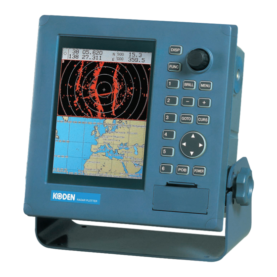
The K-link system is a network navigation system with radar, plotter, and sounder functions. The system is developed for small and medium size vessels. The Radar Plotter (MDP-621/641/640) features a high-resolution 7-inch TFT flat Liquid Crystal Display. This device provides a plotter screen, radar screen, sounder screen, and a map-overlaid radar screen as multimode screens on a single screen or split screen. -
Page 11: Model Outline
Chapter1 MDP-621/641/640 General Information Operation manual 1.3.1 Model outline 1.3.1.1 Radar Plotter GPS Sensor Transceiver RB716A (Option) 4kW Open GPS-20A(B-Type) Aerial 3 ft (RW701A-03) / Transceiver Transceiver 4 ft (RW701A-04) RB714A RB715A 2kW Radome 4kW Radome 1.2 ft 2 ft... -
Page 12: Network Outline
MDP-621/641/640 Chapter1 Operation manual General Information 1.3.2 Network outline 1.3.2.1 Radar Plotter and Sounder GPS Sensor (Option) GPS-20A(B-Type) Transceiver Open Transceiver GPS Compass Radome (Option) KGC-1 Option Option NMEA-0183 I/O Transducer RGD-600 Sounder unit CVB-20 RGD-120 Figure 1. 2 Network outline of Radar Plotter and Sounder... -
Page 13: Radar Plotter Multi-Display
Chapter1 MDP-621/641/640 General Information Operation manual 1.3.2.2 Radar Plotter multi-display GPS Sensor (Option) GPS-20A(B-Type) Transceiver Open Transceiver GPS Compass Radome (Option) KGC-1 Option Option NMEA-0183 I/O 1st Display 2nd Display RGD-600 RGD-600 RGD-120 RGD-120 Figure 1. 3 Network outline of Radar Plotter multi-display... -
Page 14: Radar Plotter Multi-Display And Sounder
MDP-621/641/640 Chapter1 Operation manual General Information 1.3.2.3 Radar Plotter multi-display and Sounder GPS Sensor (Option) GPS-20A(B-Type) Transceiver Open Transceiver GPS Compass Radome (Option) KGC-1 Option Option NMEA-0183 I/O 100/10BaseT Transducer 1st Display 2nd Display 3rd Display Sounder unit CVB-20 RGD-600... -
Page 15: About Gps
Chapter1 MDP-621/641/640 General Information Operation manual 1.5 About GPS GPS is a navigation system using 24 satellites (21 plus 3 in service) orbiting 20,183 km high from the earth every 11 hours 58 minutes. Positioning by GPS Your position is determined by calculating the distance from two satellites (in 2-dimensional positioning) or three satellites (in 3-dimensional positioning) to your position. -
Page 16: About Radar
MDP-621/641/640 Chapter1 Operation manual General Information 1.6 About radar This paragraph describes basic fundamentals and technical terms used for radar. 1.6.1 What is radar Radar is an abbreviation of radio detection and ranging. Radar uses very high frequency radio waves called microwaves. - Page 17 Chapter1 MDP-621/641/640 General Information Operation manual Radar sight distance (NM) = 2.22 ( antenna height (m) + target height (m)) Line of sight Radar Radio Earth Figure 1. 7 Radar wave propagation Targets difficult to display on screen The intensity of the reflected radio signal from a target depends on the distance, height, and size of the target, as well as its material and shape, along with the radar’s transmitter power output and...
- Page 18 MDP-621/641/640 Chapter1 Operation manual General Information A. Ghost echoes Sometimes one large object very near your boat will appear as two different targets on screen. One is the actual radar echo. The other is a ghost echo generated by a re-reflection of the original signal.
- Page 19 Chapter1 MDP-621/641/640 General Information Operation manual CAUTION When near large targets or land, your boat's mast may sometimes appear as a circular-arc shaped false echo. Main lobe False sidelobe echoes Real echo Side lobes Antenna Figure 1. 11 False echoes of radar (Caused by side lobe) D.
- Page 20 MDP-621/641/640 Chapter 2 Operation manual Equipment Composition Chapter 2 Equipment Composition Page No. Standard equipment list ............2-1 Spare parts list .................2-2 Installation materials list ............2-2 Option items list...............2-3 93161022-03 Contents...
- Page 21 MDP-621/641/640 Chapter 2 Operation manual Equipment Composition Chapter 2 Equipment Composition 2.1 Standard equipment list Item name Description Remarks Weight/Length Q’ty RGD-600 3.5kg Display unit With cover, mounting bracket and knurled bolts Radar Antenna 2kW Radome (Selection) RB714A With 10...
- Page 22 Chapter 2 MDP-621/641/640 Equipment Composition Operation manual 2.2 Spare parts list (1) MDP-621/641 Item name Description Remarks Weight/Length Q’ty Fuse F-7161-15A Fitted in CW-249 6 x30 /N30C-125V Fuse ES3-3150 For antenna motor 5 x20 (3.15A) (2) MDP-640 Item name Description...
- Page 23 Connecting Cable with 6-pin waterproof connector and one end plain Sounder unit CVB-20 Standard sounder 2.4Kg accessory items supplied 7inch Display MDP-621 Standard MDP-621 3.5Kg accessory items supplied 10inch Display MDP-1241 Standard MDP-1241 7.0Kg accessory items supplied ATA Board MRE-310...
- Page 24 Chapter 2 MDP-621/641/640 Equipment Composition Operation manual LTWD-08BFFA-L180 watertight connector (LTW) Flush mount COM7/MRD99.FM.KIT Sealing kit Operation MDP-600SER.OM.E English manual Final drawing MDP-621.FP English/Japanese MDP-641.FP MDP-640.FP Installation MDP-621.ID English/Japanese drawing MDP-641.ID MDP-640.ID Approval MDP-621.AD English/Japanese drawing MDP-621.AD MDP-640.AD Test data MDP-621.TD.E...
- Page 25 MDP-621/641/640 Chapter 3 Operation manual Specifications Chapter 3 Specifications Page No. General ..................3-1 Radar section ................3-2 3.2.1 General.......................3-2 3.2.2 Antenna specifications ..................3-2 3.2.3 Display specifications................... 3-2 3.2.4 ATA specifications ....................3-3 Plotter section................3-3 Sounder section...............3-4 Power requirements ..............3-6 Environmental conditions............3-6 External dimensions and weight ..........3-7...
-
Page 26: Chapter 3 Specifications
MDP-621/641/640 Chapter 3 Operation manual Specifcications Chapter 3 Specifications (Specifications are subject to change without notice) 3.1 General (1) Display 7inch color TFT Liquid Crystal Display (Landscape mode), 480 x 640 dots (2) Available display type Radar, Chart plotter, Radar with map display overlaid, sounder and multiple display... -
Page 27: Radar Section
Chapter 3 MDP-621/641/640 Specifcications Operation manual 3.2 Radar section 3.2.1 General (1) Range resolution Better than 30m (RB714A) Better than 25m (RB715A, RB716A) (2) Minimum range 30m or the less (RB714A) 25m or the less (RB715A, RB716A) (3) Range accuracy Better than 0.9% or 8m, whichever is the greater... -
Page 28: Ata Specifications
MDP-621/641/640 Chapter 3 Operation manual Specifcications (2) Preheat time 2 minutes (3) Connecting cable Standard 10m (100m maximum for all models except RB714A, which is 30m) (4) Functions (a) Display type PPI, semi-3D, Dual PPI (b) Display mode HU, NU or SU , CU, TM... -
Page 29: Sounder Section
Chapter 3 MDP-621/641/640 Specifcications Operation manual (7) Plotting interval Time: 1, 2, 5, 10, 20, 30, 60, 120, 300, 600 seconds Range: 0.01, 0.02, 0.05, 0.1, 0.2, 0.5, 1.0, 2.0, 5.0, 10 Unit in nm sm km (8) Plotting color... - Page 30 MDP-621/641/640 Chapter 3 Operation manual Specifcications (4) Depth unit m, ft, fm, I.fm, J.fm (5) Depth scale 5 - 10 (2.5 step), 10 - 100 (5 step) 100 - 400 (10 step), 400 - 1000 (50 step) 1000 - 1200 (100 step) unit in m, fm, I.fm, J.fm 10 - 20 (5 step), 20 –...
-
Page 31: Power Requirements
Chapter 3 MDP-621/641/640 Specifcications Operation manual (25) Alarms Bottom alarm, fish alarm, water temperature alarm (26) Other functions PRF, smoothing, draft adjustment, bottom detection start position, bottom detection level, sonic correction, water temperature correction, ship’s speed correction 3.5 Power requirements (1) DC operation Input voltage: 10.8 to 31.2 VDC... -
Page 32: External Dimensions And Weight
MDP-621/641/640 Chapter 3 Operation manual Specifcications 3.7 External dimensions and weight 3.7.1 Display Dimensions: 247 (H) x 220 (W) x 133.5 (D), unit in mm Weight: 3.5 kg 133.5 3.7.2 Radar antenna 3.7.2.1 RB714A Dimensions: 220 (H) x 448 (W) x 448 (D), unit min... -
Page 33: Rb715A
Chapter 3 MDP-621/641/640 Specifcications Operation manual 3.7.2.2 RB715A Dimensions: 255 (H) x 636 (W) x 636 (D), unit in mm Weight: 10 Kg (660) 3.7.2.3 RB716A Dimensions: 450 (H) x 1034 (W) x 390 (D) RW701A-03 , unit in 0mm... - Page 34 MDP-621/641/640 Chapter 4 Operation manual Installation Chapter 4 Installation Page No. Installation consideration ............ 4-1 Unpacking each component ..........4-1 Inspection of each unit and the accessories ..... 4-1 The units setting ..............4-1 4.4.1 Display unit installation ................4-1 4.4.1.1 Table mounting..................
-
Page 35: Chapter 4 Installation
MDP-621/641/640 Chapter 4 Operation manual Installation Chapter 4 Installation 4.1 Installation consideration General Qualified service technicians shall perform the installation of MDP-600 series in accordance with instructions: (1) Unpacking each component (2) Inspection of each unit and the accessories (3) Checking the ship’s mains voltage and current capacity... - Page 36 Chapter 4 MDP-621/641/640 Installation Operation manual Display Unit in mm (inch) Fixing screws M5 screw, 4 pcs Mounting bracket Knurled fixing bolt (6 5/8) (3 1/8) Figure 4.1 Fitting detail of display (3 15/16) (3 1/8) (3 1/8) Figure 4.2 Service space required for display...
-
Page 37: Flush Mounting
MDP-621/641/640 Chapter 4 Operation manual Installation 4.4.1.2 Flush mounting (1) Cut a rectangle opening that measures 207(H) mm x 212(W) mm. (2) Loosen two (2) fixing knobs that fasten the display unit onto the mounting bracket. (3) Remove four (4) plastic screw covers, which are fitted on each corner of the display front face. -
Page 38: Scanner Unit
Chapter 4 MDP-621/641/640 Installation Operation manual 4.4.2 Scanner unit Radar's target detection ability increases with the height of the scanner. The ideal location is as high as possible along the boat's keel line and clear of any obstructions. (1) Install the scanner as high as possible. -
Page 39: Shifting From The Obstacle
MDP-621/641/640 Chapter 4 Operation manual Installation 4.4.2.1 Shifting from the obstacle (1) Shifting from keel line By shifting the scanner position from the keel line to the starboard side of the boat, it is possible to move shadow zones to the port side. This makes it possible to keep a clear view to the bow. -
Page 40: Installing The Scanner Unit
Chapter 4 MDP-621/641/640 Installation Operation manual 4.4.2.2 Installing the Scanner Unit Use a mounting base such as the ones shown in Fig. 4.6, or you can install the scanner directly to a roof or other flat surface. Be certain you keep the water drain tube clear. It's located at the bottom of the scanner unit. - Page 41 MDP-621/641/640 Chapter 4 Operation manual Installation (1) For Radome antenna Chassis Radome (bottom) Platform Washer Platform Spring washer NOTE M10 Hexagonal bol Fix the antenna with four screws NOTE: Included in Installation Material Kit (2) For Open antenna Double nuts...
-
Page 42: Installing The Aerial
Chapter 4 MDP-621/641/640 Installation Operation manual 4.4.2.3 Installing the aerial Remove the protective cap covering the rotary coupler on the top of the scanner. Match the antenna radiation direction to direction of the arrow markings on the rotation base and secure the antenna in position using four M8 bolts. - Page 43 MDP-621/641/640 Chapter 4 Operation manual Installation (6) Replace the aluminum cover. Lay the cable shield into the channel machined into the aluminum housing. Be careful that the cable will not get caught up between the main unit and cover. (7) Replace the upper part of the radome being careful not to bump it against the antenna. Make sure that the cover is positioned in the correct direction as shown in Fig.4-10.
-
Page 44: Rb715A Radome Scanner
Chapter 4 MDP-621/641/640 Installation Operation manual 4.5.1.2 RB715A Radome scanner (1) Be sure that the power is off. (2) Remove the upper part of the radome from the scanner unit. Lift it vertically to avoid bumping it against the antenna. (There are four fixing screws.) - Page 45 MDP-621/641/640 Chapter 4 Operation manual Installation Antenna Stern side Shield cover Cable shield Fixing plate Radome (bottom) Rubber ring Fix connector on PCB (X11, X12) Interconnecting cable Inner shield X11 (Connect here) X12 (Connect here) Radome (bottom) Fitting interconnecting cable Figure 4.
-
Page 46: Interconnecting Cable (Rb716A)
Chapter 4 MDP-621/641/640 Installation Operation manual 4.5.1.3 Interconnecting cable (RB716A) (1) Be sure that the power is off. (2) Use a socket wrench to remove the back cover of scanner unit. (3) Remove the two bolts securing the transceiver. (4) Remove the connectors to the motor X1 and to the heading switch X2. Pull out the transceiver, and put it separates over 5cm from iron. - Page 47 MDP-621/641/640 Chapter 4 Operation manual Installation TR unit fixing bolts Heading switch connector (X2) Motor connector (X1) Fixing bolt Clamp Fixing plate Inter-connection cable This part enlarged Fixing bolt Cable shielding terminal When the braid was Washer covered with heat-shrink tube, remove any of it.
-
Page 48: Grounding Wire
Chapter 4 MDP-621/641/640 Installation Operation manual 4.5.1.4 Grounding wire WARNING Connect all grounding wires before connecting the power supply cable to prevent a shock hazard from leakage current. Connect a grounding wire from one of the bolts on the scanner base as shown in Figure 4.13. (The crimp terminal and grounding wire are customer-supplied items.) -
Page 49: System Connection
MDP-621/641/640 Chapter 4 Operation manual Installation 4.5.2 System connection 4.5.2.1 Connection of stand-alone system GPS sensor or GPS Compass (Option) RB716A GPS-20A(B-Type) KGC-1 RB714A RB715A Antenna cable (5m cable w th (NMEA 0183 input) 10m cable with connector (standard connector) - Page 50 Chapter 4 MDP-621/641/640 Installation Operation manual 4.5.2.2 Connection of two devices system GPS sensor or GPS Compass (Option) RB716A GPS-20A(B-Type) KGC-1 RB714A RB715A (5m cable with (NMEA 0183 input Antenna cable (10m cable connector) See para 4.5.2.1) 10m cable with connector (standard)
-
Page 51: Connection Of Multi Device System
MDP-621/641/640 Chapter 4 Operation manual Installation 4.5.2.3 Connection of multi devices system GPS sensor or GPS Compass (Option) RB716A GPS-20A(B-Type) KGC-1 RB714A RB715A (5m cable w th (NMEA 0183 input Antenna cable connector) See para 4.5.2.1) 10m cable with connector (standard) -
Page 52: Power Supply Cable
Chapter 4 MDP-621/641/640 Installation Operation manual 4.6 Power supply cable Power should be fed through a switch and protective fuses (or circuit breakers), as shown below. WARNING: Do not apply over 31.2 VDC to the display unit or it may be damaged. -
Page 53: Connector Pinouts
MDP-621/641/640 Chapter 4 Operation manual Installation 4.7 Connector pinouts NMEA in/out 1: GND 2: TX 3: GND 3:NC 4: RX+ 4:NC 5: RX- 5:GND 6: NC LAN in/out 1: LPTX+ 2: LPTX- 3: LPRX+ 4: LPRX- 5: GND) Ext buzzer output... -
Page 54: Adjustment After Installation
Chapter 4 MDP-621/641/640 Installation Operation manual 4.8 Adjustment after installation Before you turn the unit on, check the following points to make sure the system operates properly. (1) Is the ship’s supply voltage and current within the rated range? (2) Is the connection between the display and external sensor units correct? (3) Are the cables routed and connected properly? 4.8.1 Setting up network... - Page 55 MDP-621/641/640 Chapter 5 Operation manual Basic operation Chapter 5 Basic Operation Page No. Operating panel..............5-1 Turning the power supply on and off........5-3 5.2.1 Turning the power supply on..............5-3 5.2.2 Turning the power supply off..............5-3 Operating the soft keys ............5-4 Selecting display screen/changing registration screen..
-
Page 56: Chapter 5 Basic Operation
MDP-621/641/640 Chapter 5 Operation manual Basic operation Chapter 5 Basic Operation 5.1 Operating panel The operating panel comprises of 16 push-switch keys, a rotary control, a pointing keypad and a C-MAP card slot. The operating panel performs all operations of Radar, Plotter, Sounder, NAV etc. - Page 57 Chapter 5 MDP-621/641/640 Basic operation Operation manual GOTO Displays the destination and route soft menu. CURS Turns on/off the cross cursor when operating the Plotter. Performs soft menu operations. FUNC Changes the operating screen display. Used for moving the cross cursor and map as well as menu selection.
-
Page 58: Turning The Power Supply On And Off
A buzzer sounds and OK is SYSTEM displayed if system passes or NG is BATTERY displayed if system fails. For battery replacement consult the nearest KODEN dealer. Approx. 10sec. later CAUTION 38 05.620 15.3 138 27.311 359.5 The previous display shown before the unit was turned off will be shown after approx. -
Page 59: Operating The Soft Keys
Chapter 5 MDP-621/641/640 Basic operation Operation manual 5.3 Operating the soft keys The soft keys (1 to 6) are primarily used in the operation of the Plotter, Radar, Sounder and NAV Unit but are also used in the operation of each function such as the “DISP” key’s display screen selection function, the “BRILL”... -
Page 60: Selecting Display Screen/Changing Registration Screen
MDP-621/641/640 Chapter 5 Operation manual Basic operation 5.4 Selecting display screen / changing registration screen The unit can display a combination of Plotter, Radar, Plotter/Radar Overlay, Radar 3D, Sounder, Compass and Highway screen displays. These screen displays are selected from 10 different types of previously registered screens. - Page 61 Chapter 5 MDP-621/641/640 Basic operation Operation manual (NOTE) No additional operation is available for the NAV Screen, Compass and Highway display. Each screen has the following data shown. To have these data displayed, the connection of an associate sensor or navigation device is required. If no data is supplied, a series of letter X will be displayed in each data window.
- Page 62 MDP-621/641/640 Chapter 5 Operation manual Basic operation A ship’s profile shown in the center of the compass display indicates own ship’s course and a pink arrow points the waypoint bearing. The XTE bar graph indicates the course deviation and a set of triangles (three for each direction) is a steering indicator.
-
Page 63: Selecting The Display Screen
Chapter 5 MDP-621/641/640 Basic operation Operation manual 5.4.2 Selecting the display screen (1) Press the “DISP” key. The display screen selection mode appears. DISP SELECT is displayed to indicate screen selection mode. DISP SELECT CREATE SELECT DISPLAY MODE ENTER (2) Using the rotary control, position the cursor over the icon of the screen to be displayed. -
Page 64: Changing The Registration Screen
MDP-621/641/640 Chapter 5 Operation manual Basic operation 5.4.3 Changing the registration screen (Making an original screen) (1) Press the “DISP” key. The display screen selection mode appears. DISP SELECT is displayed to indicate screen selection mode. DISP SELECT CREATE DISPLAY... -
Page 65: Basic Operation
Chapter 5 MDP-621/641/640 Basic operation Operation manual (3) Press soft key “1” ( CREATE ). The registration screen change mode screen appears. The screen created in the screen Registration screen change mode screen mode is displayed. Initially, previous screen (screen changed) displayed. - Page 66 MDP-621/641/640 Chapter 5 Operation manual Basic operation Select Radar icon. The icon is now displayed with Plotter in top, Radar in bottom. DISP CREATE FULL PLOT RADAR SNDR screen OVRLY BOTTM CMPAS ENTER OV/3D HIWAY PL/SD (8) Press soft key “6” ( ENTER ).
-
Page 67: Setting Up Display Colors And Adjusting Screen Display Brightness / Panel Illumination
Chapter 5 MDP-621/641/640 Basic operation Operation manual 5.5 Setting up display colors and adjusting screen display brightness / panel illumination By pressing the “BRILL” key, the soft menu for the screen display brightness adjustment (SCREEN), the panel illumination adjustment (PANEL) and the display color settings (COLOR) is displayed. Each one can be adjusted/setup by selecting either SCREEN PANEL or COLOR. -
Page 68: Adjusting The Panel Illumination
MDP-621/641/640 Chapter 5 Operation manual Basic operation 5.5.2 Adjusting the panel illumination (1) Press soft key “2” (PANEL). A panel illumination adjustment box is displayed lower left corner. (2) Using the rotary control, adjust the panel illumination. PANEL Moving the rotary control in a clockwise direction will increase the illumination. -
Page 69: Changing The Operating Screen Via The Func Key
Chapter 5 MDP-621/641/640 Basic operation Operation manual 5.6 Changing the operating screen via the FUNC key The unit displays a combination of 2 or 3 screens. The “FUNC” key is used in selecting the operating screen from the multiple screens displayed in the display mode. -
Page 70: Operating The Cursor On/Off Key
MDP-621/641/640 Chapter 5 Operation manual Basic operation 5.7 Operating the cursor ON/OFF key When the Plotter screen is active the cross cursor is turned on/off by pressing the ”CURS” key. 38 05.620 15.3 38 05.620 15.3 138 27.311 359.5 359.5 138 27.311... -
Page 71: Operating The Pointing Keypad
Chapter 5 MDP-621/641/640 Basic operation Operation manual Cancel the audio alarm. (The POB operation continues) CLEAR The POB position is updated to current UPDATE position. CANCEL Cancels the POB registration. RETURN 5.9 Operating the pointing keypad The pointing keypad is used in moving the cross cursor in the Plotter and Radar screens, scrolling the map, and changing the menu settings, etc. -
Page 72: Inserting The C-Map Card / User C-Card
MDP-621/641/640 Chapter 5 Operation manual Basic operation 5.10 Inserting the C-MAP card / User C-Card When inserting or removing the C-MAP card, the cover shown in the diagram below opens and closes. The cover opens in the direction of the arrow. Make sure you close the cover all the way until you hear it click into place. - Page 73 MDP-621/641/640 Chapter 6 Operation manual Plotter operation Chapter 6 Plotter Operation Page No. Plotter screen................ 6-1 Changing the scale of the screen........6-1 Screen shift ................6-2 Operating the Plotter via the soft keys ....... 6-3 6.4.1 Registering the mark................6-6 6.4.2...
-
Page 74: Chapter 6 Plotter Operation
MDP-621/641/640 Chapter 6 Operation manual Plotter operation Chapter 6 Plotter Operation 6.1 Plotter screen Navigation data display area 15. 3 38 05. 620 138 27. 311 359. 5 Positioning DGPS 05.123N mode Cross cursor information NU(T) 27.611E Display 2.3nm mode... -
Page 75: Screen Shift
Chapter 6 MDP-621/641/640 Plotter operation Operation manual The scale can be changed by using “fixed-scale” and/or “auto-scale” from the soft menu. Refer to “Operating via the soft menu” Note: To read the map of a new place from the C-MAP card by using the network, it will be displayed after a few seconds. -
Page 76: Operating The Plotter Via The Soft Keys
MDP-621/641/640 Chapter 6 Operation manual Plotter operation 6.4 Operating the Plotter via the soft keys (1) Soft menu configuration As shown below, the Plotter soft menu consists of a top menu (PAGE1, PAGE2) with a function menu as well as a destination / route menu that are activated by the “GOTO” key. - Page 77 Chapter 6 MDP-621/641/640 Plotter operation Operation manual The destination / route navigation menu activated by the “GOTO” key GOTO PLOTTER GOTO CURSOR CURSOR DELETE GOTO WP NAV ENTER ROUTE SERRCH M NO SYMBOL SAVE CLEAR ON / OFF ON / OFF...
- Page 78 MDP-621/641/640 Chapter 6 Operation manual Plotter operation (2) Displaying the soft menu The soft menu is displayed at the right of the screen by pressing a soft key 1 to 6, the FUNC key and then the GOTO key. When the soft menu for Radar, Sounder and NAV DATA is displayed and the FUNC key is pressed the menu changes to Plotter.
-
Page 79: Registering The Mark
Chapter 6 MDP-621/641/640 Plotter operation Operation manual 6.4.1 Registering the mark The system can register 8,300 points of mark data. All marks can be used in waypoint and route navigation. When the cross cursor is ON, the mark is registered to the cursor position. Otherwise, when the cross cursor is OFF, the mark is registered to own ship’s position. -
Page 80: Erasing The Mark
MDP-621/641/640 Chapter 6 Operation manual Plotter operation 6.4.2 Erasing the mark When the cross cursor is on, the mark selected by the cursor is erased. When the cross cursor is off, select and erase the mark’s color and shape. 6.4.2.1 Method of selecting and erasing with the cursor When the cross cursor is not displayed, press the ”CURS”... -
Page 81: Method Of Selecting And Erasing The Mark's Color And Shape
Chapter 6 MDP-621/641/640 Plotter operation Operation manual 6.4.2.2 Method of selecting and erasing the mark’s color and shape NOTE: The CURS key needs to be deleted in this operation. To do so press the ”CURS” key. Display the soft menu (PLOTTER/PAGE1) and press the ”MARK ERASE” key. -
Page 82: Displaying The Ship's Track
MDP-621/641/640 Chapter 6 Operation manual Plotter operation 6.4.3 Displaying the ship’s track Display the soft menu (PLOTTER/PAGE1) and press the ”TRACK” key. The ship’s track settings menu is displayed. PLOTTER/PAGE1/TRACK PLOTTER PAGE1 Every time “TRACK” is pressed the track is switched ON and OFF. -
Page 83: Erasing The Ship's Track
Chapter 6 MDP-621/641/640 Plotter operation Operation manual 6.4.4 Erasing the ship’s track There are 2 ways of erasing the ship’s track. One way is to erase a selected ship’s track color, the other is to erase a ship’s track in an assigned area. -
Page 84: Selecting The Ship's Track Color And Erasing
MDP-621/641/640 Chapter 6 Operation manual Plotter operation 6.4.4.2 Selecting the ship’s track color and erasing When the cross cursor is displayed please press the “CURS” key to turn the cross cursor off. Display the soft menu (PLOTTER/PAGE1) and press the ”TRACK ERASE” key. -
Page 85: Changing The Screen Display Mode
Chapter 6 MDP-621/641/640 Plotter operation Operation manual 6.4.5 Changing the screen display mode There are 3 different types of screen display modes available; NORTH-UP (N-UP) / SOUTH-UP (S-UP), COURSE-UP (C-UP) and HEAD-UP (H-UP). TRUE MOTION (map position fixed) and RELATIVE MOTION (own ship’s position fixed) can be selected in N-UP as well as S-UP and C-UP modes. -
Page 86: Moving To The Center Of The Screen
MDP-621/641/640 Chapter 6 Operation manual Plotter operation 6.4.6 Moving to the center of the screen If you want to move the cross cursor or own ship’s position to the center of the screen use the soft menu’s ”CENTER” function. Display the soft menu (PLOTTER/PAGE2). -
Page 87: Fixed Scale Function
Chapter 6 MDP-621/641/640 Plotter operation Operation manual 6.4.8 Fixed scale function The screen scale can be changed by using the fixed scale function in the soft menu. When the cross cursor is on, the zoom in / zoom out center position becomes the position of the cursor. -
Page 88: Viewing The Map Information
MDP-621/641/640 Chapter 6 Operation manual Plotter operation 6.4.9 Viewing the map information The C-MAP card contains a large quantity of information. When the cross cursor is off, own ship’s position information is displayed. When the cross cursor is on, information on the cursor’s position is displayed. -
Page 89: Drawing
Chapter 6 MDP-621/641/640 Plotter operation Operation manual 6.4.10 Drawing The graphics memory holds 500 points. The soft menu (PLOTTER/PAGE1(2)/P FUNC) is displayed. PLOTTER/PAGE1(2)/P FUNC PLOTTER PAGE1 INFO DRAW Drawing input menu is displayed. CREATE DRAW Drawing delete menu is displayed. -
Page 90: Erasing A Drawing
MDP-621/641/640 Chapter 6 Operation manual Plotter operation (1) Select the drawing color with the COLOR key. (2) Position the cross cursor at the origin of the drawing. (3) Press the “ENTER” key. (4) Position the cross cursor at the next point of the drawing and press the ”ENTER” key. -
Page 91: Editing A Drawing
Chapter 6 MDP-621/641/640 Plotter operation Operation manual (2) Erasing an assigned area method When the cross cursor is not displayed press the “CURS” key to turn the cross cursor on. Press the “DRAW ERASE” key to display the drawing erase menu. - Page 92 MDP-621/641/640 Chapter 6 Operation manual Plotter operation (1) Moving a drawing (node) Press the “MOVE” key. The drawing (node) move menu and message are displayed. (a) Position the cross cursor on the node to be moved. PLOTTER PLOTTER PAGE1 PAGE1 (b) Press the “ENTER”...
-
Page 93: Auto-Scale
Chapter 6 MDP-621/641/640 Plotter operation Operation manual 6.4.11 Auto-scale If the soft key menu’s auto-scale function is set to ON during waypoint navigation, the scale of the screen is automatically adjusted so that the waypoint position can be viewed at all times on the screen display. -
Page 94: Setting The Waypoint / Route Navigation
MDP-621/641/640 Chapter 6 Operation manual Plotter operation 6.5 Setting the waypoint / route navigation There are 2 methods available in setting the destination and route navigation. One method is to use the destination and route positions directly assigned with the cross cursor, the other is to use the previously mark registered and route registered position data. -
Page 95: Designate The Waypoint From The Mark Registered Position
Chapter 6 MDP-621/641/640 Plotter operation Operation manual 6.5.2 Designate the waypoint from the mark registered position Press the GOTO key to display the soft (GOTO) menu (PLOTTER/GOTO) and then press ”WPT”. The destination (mark) settings menu and WPT LIST are displayed. - Page 96 MDP-621/641/640 Chapter 6 Operation manual Plotter operation (2) Deleting the registration data (a) Move the line cursor over the data to be deleted. (b) Press the “DELETE” key. (c) The soft menu turns as shown on the right. (d) By pressing the “YES” key, the data selected by the line cursor is...
- Page 97 Chapter 6 MDP-621/641/640 Plotter operation Operation manual (a) Setting the mark number Press the “M NO” key. The following soft menu and mark number settings box are displayed. Enter the search start number and the search end number. If the ”ENTER” key is pressed, the entry is completed.
- Page 98 MDP-621/641/640 Chapter 6 Operation manual Plotter operation (c) Setting the mark shape Press the “SHAPE” key to display the SHAPE settings box. Select the shape of the mark you want to search for. SHAPE Use the up / down key to set the shape.
- Page 99 Chapter 6 MDP-621/641/640 Plotter operation Operation manual Press the “SET D DISP” key to display the following waypoint list. Marks, mark number and data display (lat/lon, comment/depth or date/time) can be turned on or off by pressing the relevant key described below.
- Page 100 MDP-621/641/640 Chapter 6 Operation manual Plotter operation (5) Editing the data selected by the line cursor Changes the registered data and entering new data to an unregistered number. Move the line cursor over the data to be edited or the number for the new data entry and press the ”EDIT”...
- Page 101 Chapter 6 MDP-621/641/640 Plotter operation Operation manual (c) Changing or entering the data Position the line cursor on COMMENT, LAT, LON or DEPTH and press the ”SELECT” key. The block cursor is displayed at the start of the data. Carry out data editing or data entry.
-
Page 102: Route Navigation By Recalling The Route Registered Data
MDP-621/641/640 Chapter 6 Operation manual Plotter operation 6.5.3 Route navigation by recalling the route registered data Press the GOTO key to display the soft (GOTO) menu (PLOTTER/GOTO) and then press ”ROUTE”. The route settings menu and ROUTE LIST are displayed. - Page 103 Chapter 6 MDP-621/641/640 Plotter operation Operation manual (1) Commencing route navigation Move the line cursor over the route data to be used for navigation. Press the “GOTO RT NAV” key to display the soft menu shown below. Select forward direction or backward direction.
- Page 104 MDP-621/641/640 Chapter 6 Operation manual Plotter operation (3) Changing the data display contents Every time the “D DATA CHG” key is pressed, the displayed data of the ROUTE LIST changes between COMMNET and DATE TIME ROUTE LIST R NO COMMENT...
-
Page 105: Resetting The Origin Of The Waypoint And Route Navigation
Chapter 6 MDP-621/641/640 Plotter operation Operation manual 6.5.4 Resetting the origin of the waypoint and route navigation Can only be reset when conducting waypoint and route navigation. Press the GOTO key to display the soft menu (PLOTTER/GOTO). The soft (GOTO) menu is displayed. -
Page 106: Destination Skip
MDP-621/641/640 Chapter 6 Operation manual Plotter operation 6.5.6 Destination skip During route navigation the current waypoint is skipped to the next (latest) waypoint. Can only be reset when conducting destination and route navigation. Press the GOTO key to display the soft menu (PLOTTER/GOTO). - Page 107 MDP-621/641/640 Chapter 7 Operation manual Radar operation Chapter 7 Radar operation Page No. Radar screen ................. 7-1 Getting started ..............7-2 Changing the detection range ..........7-3 Operating the Radar via the soft keys ........ 7-4 7.4.1 Adjusting the GAIN, STC and FTC ............7-6 7.4.2...
-
Page 108: Chapter 7 Radar Operation
MDP-621/641/640 Chapter 7 Operation manual Radar operation Chapter 7 Radar Operation 7.1 Radar screen The Figure 1 shows the radar screen display where all possible screen presentations are shown. Pulse length Navigation data display area 15. 3 38 05. 620 138 27. -
Page 109: Getting Started
Chapter.7 MDP-621/641/640 Radar operation Operationmanual 7.2 Getting started Note: The radar operation is only available only when the RADAR display mode is selected. Refer to Para 5.4.2 in Chapter 5 for choosing the display mode. After the magnetron has completed its warm-up of approx. 2 minutes, STBY is displayed on the screen. -
Page 110: Changing The Detection Range
MDP-621/641/640 Chapter 7 Operation manual Radar operation 7.3 Changing the detection range If the RANGE UP “+” key is pressed, a longer range is selected. If the RANGE DOWN “-” key is pressed, a shorter range is selected. The detection range can be registered (for use / not for use) via Range Setup in the Radar menu. -
Page 111: Operating The Radar Via The Soft Keys
Chapter.7 MDP-621/641/640 Radar operation Operationmanual 7.4 Operating the Radar via the soft keys (1) Configuration of the soft menu The Radar soft menu consists of a top menu (PAGE1, PAGE2) and a function menu as shown below. The operating screen can be changed via the “FUNC” key only when the top menu is displayed. - Page 112 MDP-621/641/640 Chapter 7 Operation manual Radar operation (2) Displaying the soft menu The soft menu is displayed at the right of the screen by pressing a soft key from 1 to 6 or the FUNC key. When the soft menu for the Plotter, Sounder or NAV DATA is displayed and the FUNC key is pressed, the menu changes to Radar.
-
Page 113: Adjusting The Gain, Stc And Ftc
Chapter.7 MDP-621/641/640 Radar operation Operationmanual 7.4.1 Adjusting the GAIN, STC and FTC There are 2 methods available, manual and auto, for adjusting the GAIN, STC and FTC. Using the manual method allows the user to control GAIN, STC, and FTC individually, while auto method sets these optimized automatically. - Page 114 MDP-621/641/640 Chapter 7 Operation manual Radar operation (2) Manual adjustment In the manual adjustment mode (AUTO OFF), the GAIN, STC and FTC are adjusted individually by pressing the corresponding key (GAIN, STC or FTC key) of the soft menu. RADAR/PAGE1...
-
Page 115: Measuring The Bearing / Distance Ebl1, Vrm1
Chapter.7 MDP-621/641/640 Radar operation Operationmanual 7.4.2 Measuring the bearing / distance EBL1, VRM1 By using the bearing cursor (EBL1 the target bearing can be determined. By using the distance marker (VRM1), the distance to the target can be determined. (1) EBL1 Display the soft menu (RADAR/PAGE2) and press the ”EBL1”... -
Page 116: Changing The Display Mode
MDP-621/641/640 Chapter 7 Operation manual Radar operation 7.4.3 Changing the display mode Changes the Radar screen mode. Display the soft key menu (RADAR/PAGE2) and press the ”MODE” key. Every time the mode key is pressed the display mode changes from H UP N UP / S UP C UP TM H UP. -
Page 117: Measuring The Bearing / Distance Ebl2, Vrm2
Chapter.7 MDP-621/641/640 Radar operation Operationmanual 7.4.5 Measuring the bearing / distance EBL2, VRM2 By using the bearing cursor (EBL2 the target bearing can be determined. By using the distance marker (VRM2), the distance to the target can be determined. (1) EBL2 (a) Display the soft key menu (RADAR/PAGE1 (2)/R FUNC/MARK) and press the ”EBL2”... -
Page 118: Measuring The Bearing And Distance Between 2 Points (Float)
MDP-621/641/640 Chapter 7 Operation manual Radar operation 7.4.6 Measuring the bearing and distance between 2 points (FLOAT) If the FLOAT function is set to ON, the starting point of EBL2 and VRM2 is moved to the position of the cross cursor. -
Page 119: Deleting The Ship's Heading Line
Chapter.7 MDP-621/641/640 Radar operation Operationmanual 7.4.8 Deleting the ship’s heading line When targets are stacked up on the heading line and are difficult to see, the heading line can be temporarily deleted from the screen. (1) Display the soft menu (RADAR/PAGE1 (2)/R FUNC/MARK). -
Page 120: Changing The Pulse Length (Pulse)
MDP-621/641/640 Chapter 7 Operation manual Radar operation 7.4.10 Changing the pulse length (PULSE) The pulse length is automatically changed if the range setting is changed. However, 2 types of pulse lengths can be selected when operating in middle range. Short pulse (SHORT) has a high range discrimination giving a sharp image. -
Page 121: Enlarging The Screen Image (Zoom)
Chapter.7 MDP-621/641/640 Radar operation Operationmanual 7.4.12 Enlarging the screen image (ZOOM) Enlarges the image area at the cross cursor to twice the size. Use the following procedures. (1) Using the four way arrow key, move the cross cursor to a position on the screen for zooming. -
Page 122: Off-Center (Off-C)
MDP-621/641/640 Chapter 7 Operation manual Radar operation 7.4.13 OFF-CENTER (OFF-C) The OFF-CENTER function moves own ship’s position to a position assigned by the cross cursor in order to change the viewable area. Use the following procedure. (1) Using the pointing keypad, move the cross cursor to a position on the screen that will be the center position of the OFF-CENTER image. -
Page 123: Alarm (Gz)
Chapter.7 MDP-621/641/640 Radar operation Operationmanual 7.4.14 Alarm (GZ) The alarm function sounds a warning when a target enters a predefined area (IN MODE), or alternatively, when the last target leaves the area (OUT MODE). The alarm area can be set with a specific angle and distance. Use the following procedure. -
Page 124: Setting Up The Power Save Function (Sleep)
MDP-621/641/640 Chapter 7 Operation manual Radar operation Turning off the alarm Pressing any key while the alarm is activated will turn the alarm off. However, since the alarm function is still active the alarm may sound again. To turn the alarm function off, set to “GZ OFF” as shown above. -
Page 125: On/Off Of Variable Range Function(V Rng)
Chapter.7 MDP-621/641/640 Radar operation Operationmanual When setting the power save function If the power save function is set up while the radar is transmitting, the power save mode will be activated 30 seconds after actual setting. When a key is pressed during power save mode operation A) If a key is pressed during the power save mode operation, the power save mode is terminated and the 2-minute timer is activated. -
Page 126: Setting Up The Ata (Automatic Tracking Aid)
MDP-621/641/640 Chapter 7 Operation manual Radar operation 7.4.18 Setting up the ATA (Automatic Tracking Aid) NOTE: The ATA UNIT (MRE-310) is needed for ATA operation. The ATA is an abbreviation of Automatic Tracking Aid and its function is such that it detects and tracks the target based on its positional changes in the past, obtained from measuring its distance and bearing, and estimates the target movement. - Page 127 Chapter.7 MDP-621/641/640 Radar operation Operationmanual RADAR/PAGE1(2)/R FUNC/ATA RADAR Acquires the target. (Maximum of 10 targets) PAGE1 Position the cross cursor over the target to be acquired and press the key. Once the target has been acquired an ATA tracking symbol and a target number are displayed on the screen.
-
Page 128: Setting Up The Tuning (Tune)
MDP-621/641/640 Chapter 7 Operation manual Radar operation 7.4.19 Setting up the tuning (TUNE) Changes the tuning function between automatic and manual and performs manual tuning adjustment. Display the soft menu (RADAR/PAGE1(2)/R FUNC/TUNE) to carry out tuning. (1) Changing between Auto/Manual tuning... -
Page 129: Ppi/Semi-3D Screen
Chapter.7 MDP-621/641/640 Radar operation Operationmanual 7.5 PPI/SEMI-3D screen The picture mode is a dual mode display with PPI screen shown at the top and SEMI-3D screen at the bottom of the screen. In the SEMI-3D screen, the azimuth information is displayed in X-axis, the distance in Y-axis and the radar echo strength in Z-axis in a semi-real presentation. - Page 130 MDP-621/641/640 Chapter 8 Operation manual Sounder operation Chapter 8 Sounder operation Page No. Sounder screen..............8-1 Selecting the depth sounding range (RANGE) ....8-2 Operating the Sounder via the soft keys ......8-3 8.3.1 Setting up AUTO (Sounding range/shift)..........8-5 8.3.1.1 Automatic sounding range ..............
-
Page 131: Sounder Screen
MDP-1241/1240/1260/1210 Chapter 8 Operation manual Sounder operation Chapter 8 Operating the Sounder 8.1 Sounder screen The Figure 1 shows the sounder screen display where all possible screen presentations are shown. Navigation data display area Timing mark 05.020 27.611 359.4 17.8 Frequency N 135 mode... -
Page 132: Selecting The Depth Sounding Range (Range)
Chapter 8 MDP-1241/1240/1260/1210 Sounder operation Operation manual 8.2 Selecting the depth sounding range (RANGE) The depth range you want to view can be setup anywhere between the sea bottom and the sea surface. Using the RANGE UP “+” and RANGE DOWN “-“ keys, select the range between the sea bottom and sea surface you want to view. -
Page 133: Operating The Sounder Via The Soft Keys
MDP-1241/1240/1260/1210 Chapter 8 Operation manual Sounder operation 8.3 Operating the Sounder via the soft keys (1) Configuration of soft menu The Sounder soft menu consists of a top menu (PAGE1, PAGE2) and a function menu as shown below. The operating screen can be changed via the “FUNC” key only when the top menu is displayed. Top menu SOUNDER/PAGE1 GAIN... - Page 134 Chapter 8 MDP-1241/1240/1260/1210 Sounder operation Operation manual Displaying the soft menu The soft menu is displayed at the bottom of the screen by pressing a soft key from 1 to 6 or the FUNC key. When the soft menu for the Plotter, Radar or NAV DATA is displayed and the FUNC key is pressed, the menu changes to Sounder.
-
Page 135: Setting Up Auto (Sounding Range/Shift)
MDP-1241/1240/1260/1210 Chapter 8 Operation manual Sounder operation 8.3.1 Setting up AUTO (Sounding range/shift) Selects automatic sounding range, auto-shift or manual sounding range. The outline of each function is as follows: Automatic sounding range: The sounding range automatically changes to keep the sea bottom displayed on the screen at all times. -
Page 136: Adjusting The Image Sensitivity
Chapter 8 MDP-1241/1240/1260/1210 Sounder operation Operation manual 8.3.2 Adjusting the image sensitivity Display the soft menu (SOUNDER/PAGE1) and press the “GAIN” key. SOUNDER/PAGE1 NEXT AUTO GAIN SHIFT S FUNC SOUNDER RANGE Displays the manual or automatic sensitivity adjust menu. SOUNDER/PAGE1/GAIN GAIN L GAIN L ENH... -
Page 137: Auto Adjustment
MDP-1241/1240/1260/1210 Chapter 8 Operation manual Sounder operation (3) Adjusting the high frequency sensitivity If the “ GAIN” key is pressed, the GAIN adjustment box shown below is displayed. The method of operation is the same as the L GAIN method. H GAIN (4) Adjusting the high frequency enhance If the “... -
Page 138: Adjusting The Stc
Chapter 8 MDP-1241/1240/1260/1210 Sounder operation Operation manual 8.3.3 Adjusting the STC In relatively shallow areas containing lots of surface debris such as rubbish, plankton etc. the screen display will show large red and yellow areas. If a school of fish enters this area, the unit may not be able to distinguish the school from the debris. -
Page 139: Setting The Low Frequency Stc Depth
MDP-1241/1240/1260/1210 Chapter 8 Operation manual Sounder operation 8.3.3.3 Setting the low frequency STC depth If the “L DPT” key is pressed, the LDPT adjustment box shown below is displayed. Use the rotary control to adjust the depth. The depth value is indicated with a number and a bar. Moving the rotary control to the right will increase the depth. -
Page 140: Setting The Fixed Shift
Chapter 8 MDP-1241/1240/1260/1210 Sounder operation Operation manual 8.3.4 Setting the fixed shift The fixed shift function displays the sounder image within the selected depth range with reference to the preset depth (Shift setting). Display the soft menu (SOUNDER/PAGE1) and press the “SHIFT” key. The SHIFT adjustment box is displayed. -
Page 141: Selecting The Display Image
MDP-1241/1240/1260/1210 Chapter 8 Operation manual Sounder operation 8.3.5 Selecting the display image Selects the screen display mode. Display the soft menu (SOUNDER/PAGE2/MODE) and press the “D MODE” key. The display mode selection menu is displayed. Set the screen display mode using the joystick or the 10-digit keypad. -
Page 142: Changing The Frequency
Chapter 8 MDP-1241/1240/1260/1210 Sounder operation Operation manual 8.3.6 Changing the frequency Changes the sounding frequency between low frequency and high frequency. If the frequency is changed while viewing the low frequency image, the image will be changed to the high frequency image. If the frequency is changed while viewing the high frequency image, the image will be changed to the low frequency image. -
Page 143: Setting The Interference Rejection
MDP-1241/1240/1260/1210 Chapter 8 Operation manual Sounder operation 8.3.8 Setting the interference rejection In the case where another ship in the vicinity is using a sounder operating at the same frequency and transmission rate, there may be interference from that ship’s sounder displayed on the screen. This interference can be eliminated by using the IR function. -
Page 144: Setting The Screen Display Rate
Chapter 8 MDP-1241/1240/1260/1210 Sounder operation Operation manual 8.3.9 Setting the screen display rate The screen display rate value is directly related to the transmission rate from the transducer. For example 2/1 means that for every single transmission the displayed image moves by 2. To set the rate: (1) Display the soft menu (SOUNDER/PAGE2) and press the “I SPD”... -
Page 145: Setting The Alarm
MDP-1241/1240/1260/1210 Chapter 8 Operation manual Sounder operation 8.3.10 Setting the alarm The alarm function has a sea bottom alarm and a fish school alarm, which can be set individually. To set the alarm: (1) Display the soft menu (SOUNDER/PAGE2) and press the “ALARM” key. (2) The settings menu is displayed. - Page 146 Chapter 8 MDP-1241/1240/1260/1210 Sounder operation Operation manual (b) Setting the fish school alarm SOUNDER/PAGE2/ALARM D ALM RETURN D ALM F ALM F ALM SOUNDER AREA PAGE2 AREA F ALM If the F ALM AREA key is Turns the fish school pressed, the alarm area settings alarm ON/OFF.
-
Page 147: Color Clearing Operation
MDP-1241/1240/1260/1210 Chapter 8 Operation manual Sounder operation 8.3.11 Color clearing operation When the ship is underway, thin blue and white noise lines resulting from sea turbulence, background ocean noise, etc., may appear on the screen. Additionally, some fish species are always displayed in a certain color. -
Page 148: Setting The Tone
The color tone of the sounder image can be selected from 3 different types. Tone 1: 16 colors (Koden standard color mode). Tone 2: 16 colors (Koden standard color mode without white). Tone 3: 8 colors (Koden standard 8 color mode). -
Page 149: Operating The Vrm
MDP-1241/1240/1260/1210 Chapter 8 Operation manual Sounder operation 8.3.14 Operating the VRM The VRM (Distance markers) can be moved up or down on the screen. By positioning the VRM on a school of fish or on a particular target of interest, the depth of that target can be measured. The color of VRM1 is green and the color of VRM2 is yellow. -
Page 150: Adjusting The Transmission Rate
Chapter 8 MDP-1241/1240/1260/1210 Sounder operation Operation manual 8.3.16 Adjusting the Transmission rate By adjusting the signal transmission rate, screen error images resulting from the synchronization with another ship’s sounder can be eliminated. Display the soft menu (SOUNDER/PAGE1 (2)/S FUNC). The transmission rate settings menu is displayed. Set the transmission rate using the joystick or the 10digit keypad. - Page 151 MDP-621/641/640 Chapter 9 Operation manual Navigation Data operation Chapter 9 Navigation Data operation Page No. Navigation Data display ............9-1 Navigation Data operation........... 9-2 9.2.1 Changing the Navigation Data display ............9-4 9.2.2 Setting the alarms ...................9-5 93161022-03 Contents...
-
Page 152: Chapter 9 Navigation Data Operation
MDP-1241/1240/1260/1210 Chapter 9 Operation manual Navigation Data operation Chapter 9 Navigation Data Operation 9.1 Navigation Data display Navigation data such as own ship’s position, waypoint data etc. is displayed at the top of the screen The type of navigational data displayed is changed by the soft keys. Furthermore, the alarm functions associated with navigation (Arrival, anchor watch, course deviation, speed and water temperature alarm) are set via the soft keys of the Navigation Data (NAV). - Page 153 Chapter 9 MDP-1241/1240/1260/1210 Navigation Data operation Operation manual 9.2 Navigation Data operation (1) Configuration of the soft menu The Navigation Data soft menu consists of a top menu (PAGE1) and an alarm settings menu as shown below. The operating screen can be changed via the “FUNC” key only when the top menu is displayed. Top Menu NAV/PAGE1 DATA...
- Page 154 MDP-1241/1240/1260/1210 Chapter 9 Operation manual Navigation Data operation (2) Displaying the soft menu The soft menu is displayed at the bottom of the screen by pressing a soft key from 1 to 6 or the FUNC key. When the soft menu for Plotter, Radar or Sounder is displayed and the FUNC key is pressed the menu changes to Navigation Data (NAV).
-
Page 155: Changing The Navigation Data Display
Chapter 9 MDP-1241/1240/1260/1210 Navigation Data operation Operation manual (3) Deleting the soft menu The soft menu disappears from the screen approximately 5 seconds after finishing the operation. After disappearing, if the soft menu is displayed again, the displayed menu will be the previous soft menu. -
Page 156: Setting The Alarms
MDP-1241/1240/1260/1210 Chapter 9 Operation manual Navigation Data operation 9.2.2 Setting the alarms Press the “ALARM” key of the soft menu (NAV/PAGE1) to set the alarm (Arrival, anchor watch, course deviation, speed, water temperature). NAV/PAGE1 DATA ALARM NAV/PAGE1/ALARM RETURN ARR AL ANCHOR SPEED TEMP... - Page 157 Chapter 9 MDP-1241/1240/1260/1210 Navigation Data operation Operation manual (2) Anchor watch The anchor slip alarm sounds (Beep!, Beep!, Beep!) if own ship drifts outside a preset alarm area while at anchor. To activate the anchor watch alarm, set up the alarm area and then set ALARM to ON. NAV/PAGE1/ALARM ARR AL ANCHOR...
- Page 158 MDP-1241/1240/1260/1210 Chapter 9 Operation manual Navigation Data operation (4) Speed alarm The speed alarm sounds (Beep!, Beep!, Beep!) if the speed is within the set alarm range or alternatively outside the set range. The alarm will activate if the alarm range and mode are set and ALARM is set to ON. In alarm range: The alarm will sound if the speed is within the set alarm range.
- Page 159 Chapter 9 MDP-1241/1240/1260/1210 Navigation Data operation Operation manual (5) Water temperature alarm The water temperature alarm sounds (Beep!, Beep!, Beep!) if the water temperature is within the set alarm range or alternatively outside the set range. The alarm will activate if the alarm range and mode are set and ALARM is set to ON. In alarm range: The alarm will sound if the water temperature is within the set alarm range.
- Page 160 MDP-621/641/640 Chapter 10 Operation manual MENU operation Chapter 10 MENU Operation Page No. 10.1 Operating the MENU ............10-1 10.1.1 Displaying the MENU screen ..............10-1 10.1.2 Basic operation of the MENU ..............10-2 10.2 SYSTEM MENU ..............10-3 10.2.1 Setting the buzzer..................10-4 10.2.2 Setting the display .................10-5...
- Page 161 Chapter 10 MDP-621/641/640 MENU operation Operation manual Page No 10.4.6.3 Adjusting the tuning circuit (Tuning Adjust)......... 10-51 10.4.6.4 Adjusting the antenna height (Antenna) ..........10-52 10.4.6.5 Setting GAIN circuit (GAIN) ..............10-53 10.4.6.6 Setting the STC circuit (STC) ............. 10-53 10.5...
-
Page 162: Chapter 10 Menu Operation
MDP-621/641/640 Chapter 10 Operation manual MENU operation Chapter 10 MENU Operation The screens of the Plotter, Radar, Sounder, Navigation Data (NAV) and System are contained in the MENU (The initial settings screen activated by the menu key) where the adjustments and presets associated with setting up each screen can be found. -
Page 163: Basic Operation Of The Menu
Chapter 10 MDP-621/641/640 MENU operation Operation manual 10.1.2 Basic operation of the MENU Press the right key. Press the left or right key. Press the right key: Next MENU window is displayed. Press the left key: Returns to the previous MENU window. -
Page 164: System Menu
MDP-621/641/640 Chapter 10 Operation manual MENU operation 10.2 SYSTEM MENU The functions listed below are set with the SYSTEM MENU. 0 Buzzer Set 0 Buzzer Sound Set (OFF, ON) 1 Ext Buzzer Set (OFF, ON) 1 Display 0 Range & Speed Unit (nm / kt, sm / mph, km / km/h) 1 Depth Unit (m, ft, fm, I.fm, J.fm) -
Page 165: Setting The Buzzer
Chapter 10 MDP-621/641/640 MENU operation Operation manual 10.2.1 Setting the buzzer The buzzer sound and the external buzzer output are set ON or OFF via “0 Buzzer Set” of the System menu. (1) Setting the buzzer sound Open the System Menu 0 Buzzer Set 0 Buzzer Sound Set and select ON or OFF. -
Page 166: Setting The Display
MDP-621/641/640 Chapter 10 Operation manual MENU operation 10.2.2 Setting the display The range and speed units, depth units, water temperature units and position data display are set via “1 Display” of the System menu. (1) Setting the range and speed units... - Page 167 Chapter 10 MDP-621/641/640 MENU operation Operation manual (3) Setting the water temperature units Open the System Menu 1 Display 2 Temperature Unit and select either Celsius or Fahrenheit. SYSTEM Buzzer Set Display Source Set Display Cor c re tion Range & Speed Unit...
-
Page 168: Setting The Input Source
MDP-621/641/640 Chapter 10 Operation manual MENU operation 10.2.3 Setting the input source Each input data source for depth, water temperature, speed and ship’s heading is set via “2 Source Set” of the System menu. (1) Setting the depth data input source... - Page 169 Chapter 10 MDP-621/641/640 MENU operation Operation manual (3) Setting the speed data Open the System Menu 2 Source Set 2 Speed and select either SOG (Speed over ground) or STW (Speed through the water). SYSTEM Buzzer Set Display Source Set...
-
Page 170: Correction
MDP-621/641/640 Chapter 10 Operation manual MENU operation 10.2.4 Correction The magnetic correction, the magnetic source, the magnetic correction value and the value of the water temperature sensor and the speed sensor correction are all set via “3 Correction” of the System menu. - Page 171 Chapter 10 MDP-621/641/640 MENU operation Operation manual (3) Setting the magnetic correction Open the System Menu 3 Correction 2 Magnetic Set and enter the magnetic correction value. SYSTEM Buzzer Set Display Source Set Correction Cursor Type Correction Area e Magnetic...
-
Page 172: Setting The Cursor Type
MDP-621/641/640 Chapter 10 Operation manual MENU operation (5) Setting the speed correction Open the System Menu 3 Correction 4 Boat Speed and set the correction value for the boat speed. SYSTEM Buzzer Set Display Source Set Correction Cursor Type Correction... -
Page 173: Setting The Area
Chapter 10 MDP-621/641/640 MENU operation Operation manual 10.2.6 Setting the area The screen mode for the Plotter and Radar can be changed between North Up and South Up in the “5 Area Set” window of the System Menu. SYSTEM Buzzer Set... -
Page 174: Language
MDP-621/641/640 Chapter 10 Operation manual MENU operation 10.2.8 Language The on-screen display language can be selected via the System Menu 7 Language window. SYSTEM Buzzer Set Display Source Set Correction Cursor Type Area Set Language Simula o ti n English... -
Page 175: Setting Up The Network
Chapter 10 MDP-621/641/640 MENU operation Operation manual 10.2.9 Setting up the network Set up the parameters associated with the network setup SYSTEM Buzzer Set Language Display IP Address Source Set Host Name Correction Radar Source Cursor Type Chart Source Area Set... - Page 176 MDP-621/641/640 Chapter 10 Operation manual MENU operation (2) Host Name Set it as shown in the following table. Device Host Name Remarks 1st Display RADAR MDP Series 2nd Display CHART1 RGD Series 3rd Display CHART2 RGD Series Host Name Host Name Move the cursor with the left/right cursor key.
- Page 177 Chapter 10 MDP-621/641/640 MENU operation Operation manual (4) Chart Source Set it as shown in the following table. Settings Chart Source Remarks Chart Source1 RADAR MDP Series Chart Source2 CHART1 RGD Series Chart Source3 CHART2 RGD Series Chart Source1 Move the cursor with the left/right cursor key.
- Page 178 MDP-621/641/640 Chapter 10 Operation manual MENU operation (7) Gateway Address Set it as follows. Gateway Address Move the cursor with the left/right cursor key. 000.000.000.000 Change the figure with 0 1 2 3 4 5 6 7 8 9 the rotary control.
-
Page 179: System Check
Chapter 10 MDP-621/641/640 MENU operation Operation manual 10.2.10 System check SYSTEM CHECK helps you to identify a problem with your SYSTEM system. Buzzer Set Display Source Set (1) The self-check will take a few seconds to run. OK Correction indicates the items is operating properly. - Page 180 MDP-621/641/640 Chapter 10 Operation manual MENU operation a) ROM Indicates the ROM status. b) RAM Indicates the RAM status. c) Backup memory Indicates the backup memory status. d) BATTERY Indicates the backup memory battery status. e) +5V voltage Indicates the reference voltage status of the video circuit and its voltage value.
-
Page 181: Plotter Menu
Chapter 10 MDP-621/641/640 MENU operation Operation manual 10.3 Plotter MENU The functions listed below are set with the PLOTTER MENU. 0 Display 0 Track Line (Thin Line, Thick line) 1 Course Line (OFF, Long Length Line, Speed response) 2 Own Ship’s Mark (Small Circle, Large Circle , Dot , Shop’s Profile(S) , Ship’s Profile(L)) - Page 182 MDP-621/641/640 Chapter 10 Operation manual MENU operation 1 Setup 0 Plotting Interval 0 Time 1 Distance 1 Plotting Limit (2000, 4000, 7000) 2 Fix Scale 0 Fix Scale 1 1 Fix Scale 2 2 Fix Scale 3 3 Chart Correction...
- Page 183 Chapter 10 MDP-621/641/640 MENU operation Operation manual 2 Erase 0 Mark 1 Route 2 Track 3 Drawing 4 Target Track 3 Format 4 ATA Preset 0 Target Mark (OFF , ON) 1 Mark Size (Small Circle , Large Circle , Dot)
-
Page 184: Setting Up The Display
MDP-621/641/640 Chapter 10 Operation manual MENU operation 10.3.1 Setting up the display The settings associated with the Plotter’s screen display are carried out in the “0 Display” window of the Plotter Menu. PLOTTER PLOTTER Display 0 Track Line Setup Course Line User C-Card1 Own Ship’s Mark... - Page 185 Chapter 10 MDP-621/641/640 MENU operation Operation manual (3) Own Ship’s Mark Own ship’s position mark can be displayed as a [small circle], [large circle], [dot], [ship’s profile (small)] or [ship’s profile (large)]. When the mark is displayed as the [ship’s profile], the mark’s bow direction changes in accordance with the heading.
- Page 186 MDP-621/641/640 Chapter 10 Operation manual MENU operation (8) Chart Display 1,2,3 Turns ON or OFF the information display for the map data symbols (landmarks, objects, etc.). When the information display is turned ON the symbols can be set to “Display on Plotter screen/Do not display on Overlay screen”...
-
Page 187: Initial Settings (Setup)
Chapter 10 MDP-621/641/640 MENU operation Operation manual 10.3.2 Initial settings (Setup) Each setting for plotting interval, plotting limit (no. of points), fix scale and chart correction is carried out in the initial settings (Setup) menu. PLOTTER Setup Display Plotting Interval... - Page 188 MDP-621/641/640 Chapter 10 Operation manual MENU operation (3) Fix Scale 1 - 3 Activated by the soft key’s “Fix Scale” function. The scale size can be easily changed by presetting those that are frequently used in the MENU. Setting range: 0.01 3600nm.
-
Page 189: User C-Card 1 (2)
Chapter 10 MDP-621/641/640 MENU operation Operation manual 10.3.3 User C-Card 1 (2) Saves and/or deletes the mark, route, trail, graphics and other ships’ trail information to the external memory. (User C-Card). PLOTTER User C-Card 1 (2) Display Store Setup User C-Card 1... - Page 190 MDP-621/641/640 Chapter 10 Operation manual MENU operation (1) MARK STORE MARK STORE MARK BLOCK SELECTION (a) Press the “MARK BLOCK” key to display the BLOCK NO M.NO 0 BLOCK0 (0000 – 0999) MARK BLOCK SELECTION list. 1 BLOCK1 (1000 – 1999) 2 BLOCK2 (2000 –...
- Page 191 Chapter 10 MDP-621/641/640 MENU operation Operation manual (3) TRACK STORE TRACK STORE (a) Press the “FILE NAME” key to display the FILE DESTINATION FILE SELECTION FILE NAME DATE NAME selection list. (The line cursor highlights the 0 TK001 2003/10/15 1 TK002...
-
Page 192: Recall
MDP-621/641/640 Chapter 10 Operation manual MENU operation (e) When FILE NAME is assigned the tinted “STORE” key accordingly turns to normal black and becomes active. Pressing the “STORE” key permits the TARGET TRACK data to be stored into the FILE designated. - Page 193 Chapter 10 MDP-621/641/640 MENU operation Operation manual (1) MARK RECALL MARK RECALL SOURCE FILE SELECTION (a) Press the “FILE NAME” key to display the FILE NAME DATE 0 MK001 2003/10/15 SOURCE FILE SELECTION list. 1 MK002 2003/10/16 2 MK003 2003/10/17...
- Page 194 MDP-621/641/640 Chapter 10 Operation manual MENU operation (3) TRACK RECALL TRACK RECALL SOURCE FILE SELECTION (a) Press the “FILE NAME” key to display the SOURCE FILE NAME DATE FILE SELECTION list. 0 TK001 2003/10/15 1 TK002 2003/10/16 (b) Select the FILE NAME to be read out from the User...
-
Page 195: Erase
Chapter 10 MDP-621/641/640 MENU operation Operation manual 10.3.3.3Erase User C-Card 1 (2) Store Recall Erase Format Erase Mark Route Track PLOTTER Drawing Target Track ERASE XXXX ERASE FILE FILE NAME NAME Data to be erased from User C-Card. RETURN MARK RECALL... - Page 196 MDP-621/641/640 Chapter 10 Operation manual MENU operation (2) ROUTE ERASE ROUTE ERASE ERASE FILE SELECTION (a) Press the “FILE NAME” key to display the ERASE FILE NAME DATE FILE SELECTION list. 0 RT001 2003/10/15 1 RT002 2003/10/16 (b) Select the FILE NAME to be deleted from the User...
-
Page 197: Format
Chapter 10 MDP-621/641/640 MENU operation Operation manual (5) TARGET TRACK ERASE TARGET TRACK ERASE (a) Press the “FILE NAME” key to display the ERASE ERASE FILE SELECTION FILE NAME DATE SELECTION list. 0 OT001 2003/10/15 1 OT002 2003/10/16 (b) Select the FILE NAME to be deleted from the User... -
Page 198: Ata Preset
MDP-621/641/640 Chapter 10 Operation manual MENU operation 10.3.4 ATA Preset When the ATA function of the Radar is active, the target information is extracted and the target track and vector are displayed on the Plotter screen. PLOTTER Target Mark PLOTTER... - Page 199 Chapter 10 MDP-621/641/640 MENU operation Operation manual (3) Target Number Sets the target number display ON or OFF. Setting range: OFF, ON Initial setting: Target Number (4) Vector Sets the target vector display ON or OFF. Setting range: OFF, ON...
- Page 200 MDP-621/641/640 Chapter 10 Operation manual MENU operation (7) Track Color Sets the color of the target track line. The color of each target track line can be set individually for up to 10 targets. Setting range:Green, red, yellow, cyan, blue, pink, white...
-
Page 201: Radar Menu
Chapter 10 MDP-621/641/640 MENU operation Operation manual 10.4 Radar MENU The functions listed below are set with the RADAR MENU. 0 Display 0 Cursor Position (Position, DIST/BRG(REL), DIST/BRG(TRUE) 1 EBL Bearing (REL, TRUE) 2 HL Flash (OFF, ON) 3 Stern Mark... - Page 202 MDP-621/641/640 Chapter 10 Operation manual MENU operation 4 Range Setup 2 (OFF, ON) 1 12 (OFF, ON) 2 16 (OFF, ON) 3 24 (OFF, ON) 4 36 (OFF, ON) 5 48 (OFF, ON) 5 SCAN Speed (STD, HIGH) 6 Adjust...
-
Page 203: Display
Chapter 10 MDP-621/641/640 MENU operation Operation manual 10.4.1 Display Sets up the parameters associated with the Radar screen display. RADAR Display Display Cursor Position Image EBL Bearing ATA Preset HL Flash Range Setup1 Stern Mark Range Setup2 North Mark SCAN Speed... - Page 204 MDP-621/641/640 Chapter 10 Operation manual MENU operation (4) Stern Mark Sets the stern mark display ON or OFF. Initial setting: Stern Mark (5) North Mark Sets the north direction mark display ON or OFF. Initial setting: North Mark (6) WPT Mark Sets the waypoint mark display ON or OFF.
-
Page 205: Image
Chapter 10 MDP-621/641/640 MENU operation Operation manual 10.4.2 Image Sets up the parameters associated with displaying the Radar image. RADAR Image Display Pulse Table Image GZ Level ATA Preset Echo Color Range Setup1 Color Range Setup2 Own Track SCAN Speed... - Page 206 MDP-621/641/640 Chapter 10 Operation manual MENU operation (2) GZ Level Sets the guard zone detection level. The level ranges from 1 to 7 such that, as the level number increases, only targets with large signal strengths are detected and weak echoes from small targets and sea surface clutter are ignored.
- Page 207 Chapter 10 MDP-621/641/640 MENU operation Operation manual (6) Own Track Interval Set the plotting interval for own ship’s track. Selection: CONT, 15sec, 30sec, 1min, 3min, 6min Initial setting: 3min OWN Track Interval 3min (7) Hold The Hold function retains the screen image for 30 seconds after the unit is set from transmit to standby.
-
Page 208: Ata Preset
MDP-621/641/640 Chapter 10 Operation manual MENU operation 10.4.3 ATA Preset Sets up the parameters for the ATA operation. RADAR ATA Preset Display CPA Set Image TCPA Set ATA Preset VECT Set Range Setup1 VECT Mode Range Setup2 SCAN Speed Adjust (1) Closest point of approach distance (CPA Set) Sets up the desired distance for the closest point of approach. -
Page 209: Range Setup1, 2
Chapter 10 MDP-621/641/640 MENU operation Operation manual (5) ATA ON/OFF (ATA) Sets the ATA function ON or OFF. If set to OFF, the ATA function will not operate. If the ATA menu (MRE-310) is not included, the ATA cannot be set to ON. -
Page 210: Scan Speed
MENU operation 10.4.5 SCAN Speed Sets the rotation speed of the antenna. When using the RB714A 2kW Antenna (MDP-621), the rotation speed cannot be set. Set the rotation speed in the standby mode (Cannot be set while transmitting). RADAR Display... - Page 211 Chapter 10 MDP-621/641/640 MENU operation Operation manual 10.4.6.1 Adjusting the distance (TX Timing Adjust) This adjustment calibrates the distance displayed on the radar screen to the actual distance. (1) First, set radar range to 0.25nm, FTC to minimum, and GAIN to optimum. Then adjust STC until the pulse generated by the radar at the center of the screen is a round dot.
-
Page 212: Adjusting The Tuning Circuit (Tuning Adjust)
MDP-621/641/640 Chapter 10 Operation manual MENU operation HEAD DIRECTION ADJUSTMENT ADJUST WITH CONTROL KNOB PRESS ENTER KEY TO RETURN 358.8 10.4.6.3 Adjusting the tuning circuit (Tuning Adjust) This will adjust the automatic tuning circuit to its best operating point. (1) Choose several stable video images in the 6nm range or more and select the long pulse setting. -
Page 213: Adjusting The Antenna Height (Antenna)
Chapter 10 MDP-621/641/640 MENU operation Operation manual READ OPERATION MANUAL TUNE WITH CONTROL KNOB PRESS ENTER KEY TO MEMORY AUTO 10.4.6.4 Adjusting the antenna height (Antenna) Depending on the height at which the antenna is installed, it may be necessary to make the following correction. -
Page 214: Setting Gain Circuit (Gain)
MDP-621/641/640 Chapter 10 Operation manual MENU operation Echoes in short range are varied in accordance with the antenna height. Use 9 for the lowest antenna and 1 for the highest antenna. Actual adjustment of the ANTENNA HEIGHT is done by obtaining a continuous echo return of the sea clutter out to a maximum selected range. - Page 215 Chapter 10 MDP-621/641/640 MENU operation Operation manual (1) Adjustment in AUTO (AUTO1/AUTO2/HARBOR) mode (a) Select STC in the following order: MENU => Adjust => STC (b) Select AUTO 1, AUTO 2 or HARBOR in the soft menu. (c) When the screen appears, select an appropriate value from 1 to 16 with the control knob (d) Press the ENTER key to exit from this mode.
-
Page 216: Sounder Menu
MDP-621/641/640 Chapter 10 Operation manual MENU operation 10.5 Sounder MENU The functions listed below are set up with the SOUNDER MENU. 0 Display 0 Depth Display (OFF, Small, Middle, Large) 1 Depth Position (Bottom, Top) 2 Scale Display (OFF, Single, All) -
Page 217: Display
Chapter 10 MDP-621/641/640 MENU operation Operation manual 10.5.1 Display Sets up the parameters associated with the Sounder screen display. Display SOUNDER Depth Display Display Depth Position Image Scale Display Transmission Scale Position Depth Range Preset Scale Value Adjust Time Mark... - Page 218 MDP-621/641/640 Chapter 10 Operation manual MENU operation (2) Depth Position Selects the position to display the depth value. Selections: 0/ Bottom 58.5 1/ Top Initial Setting: 0/ Bottom Bottom Depth Position Bottom (3) Scale Display Selects the type of scale to display.
- Page 219 Chapter 10 MDP-621/641/640 MENU operation Operation manual (4) Scale Position Selects the position to display the scale. Selections: 0/ Side 58.5 1/ Center Initial Setting: 0/ Side Scale Position Side Center Center Side (5) Scale Value Selects the size of the displayed scale values.
- Page 220 MDP-621/641/640 Chapter 10 Operation manual MENU operation (7) Image Direction Selects the direction the image moves in dual frequency mode. Selections: 58.5 Initial Setting: Image Direction Image Direction (8) Image Split 10secs or 1min Selects the type of dual screen split.
- Page 221 Chapter 10 MDP-621/641/640 MENU operation Operation manual (10) Color Bar Scale Sets the color bar scale display ON or OFF. 10secs or 1min Selections: 0/ OFF 1/ ON 58.5 Initial Setting: 1/ ON Color Bar Scale Color Bar Scale 10-60...
-
Page 222: Image
MDP-621/641/640 Chapter 10 Operation manual MENU operation 10.5.2 Image Sets up the parameters associated with the image. Image SOUNDER Enhance Display White Line Image Transmission Smoothing Depth Range Preset Water Temp Graph Adjust (1) Enhance The dynamic range of the sounder image can be changed from 25dB to 65dB in 10dB steps and is adjusted in “Enhance”... - Page 223 Chapter 10 MDP-621/641/640 MENU operation Operation manual (3) Mix Small fish schools that return weak echoes such as white bait, etc are detected mainly by the high frequency ultrasonic returns. Detection of these types of small fish schools by the low frequency returns is difficult.
-
Page 224: Transmission
MDP-621/641/640 Chapter 10 Operation manual MENU operation (5) Water temperature graph The water temperature graph can be displayed only if the water temperature sensor is connected. 10secs or 1min Setting range: OFF, ON Water Temp Graph Water temperature graph 10.5.3 Transmission Sets up the parameters associated with the signal transmission. - Page 225 Chapter 10 MDP-621/641/640 MENU operation Operation manual (2) Output The output power is reduced if “Output” is set to “Low”. This function can be used when testing the transmitter section during maintenance. Setting range: Normal, Low Output Normal 10.5.4 Depth Range Preset This function registers the depth range from Range1 Range8.
-
Page 226: Adjust
MDP-621/641/640 Chapter 10 Operation manual MENU operation For feet 1000 1040 1080 1120 1160 1200 1240 1280 1320 1360 1400 1440 1480 1520 1560 1600 1800 2000 2200 2400 2600 2800 3000 3200 3400 3600 3800 4000 10.5.5 Adjust Sets up the parameters associated with the system (Initial settings). - Page 227 Chapter 10 MDP-621/641/640 MENU operation Operation manual (2) Bottom Det Start The setting for the bottom detection level is too large and Sets the depth at which to start bottom detection. bottom detected. Care should be taken, as bottom detection in shallow areas may not be possible if this value is too large 05.020...
- Page 228 MDP-621/641/640 Chapter 10 Operation manual MENU operation (5) Depth Selects the bottom detection function to operate at high frequency, low frequency or auto. Setting range: Auto, high frequency, low frequency. Depth Auto High (6) Sonic correction Due to the differences in the temperature and salinity of seawater, the measured depth may be slightly deeper or shallower than the real depth.
-
Page 229: Nav Menu
MENU operation Operation manual 10.6 NAV MENU The functions listed below are set up with the NAV MENU. 0 Nav Information 0 Position Data (KODEN GPS, NMEA/NETWORK, All) 1 Local Time Offset (+13:30 -13:30) 2 Time Display (12hours, 24hours) 1 GPS Set... - Page 230 MDP-621/641/640 Chapter 10 Operation manual MENU operation 2 Sentence 2 0 GTD (OFF, ON) 1 MTW (OFF, ON) 2 RMA (OFF, ON) 3 BMB (OFF, ON) 4 BMC (OFF, ON) 5 TLL (OFF, ON) 6 TTM (OFF, ON) 7 VHW...
- Page 231 Loran C Set Decca Set NMEA Output Data NMEA Monitor (1) Position Data Selects the data source for inputting own ship’s position information. Setting range: KODEN GPS, NMEA/NETWORK, All Initial setting: KODEN GPS Position Data KODEN GPS NMEA / NETWORK (2) Local Time Offset Sets the local time correction factor.
- Page 232 MDP-621/641/640 Chapter 10 Operation manual MENU operation 10.6.2 GPS Set The settings for the GPS receiver are carried out in “1 GPS Set” of the Nav MENU. GPS Set NAV Information Speed averaging GPS Set LAT Correction GPS Monitor LON Correction...
- Page 233 Chapter 10 MDP-621/641/640 MENU operation Operation manual (4) Beacon Station Selects the automatic or manual setting for the beacon stations used in the DGPS mode. If the frequency and baud rate of the area’s beacon is known, use the manual setting to set up each one individually.
- Page 234 MDP-621/641/640 Chapter 10 Operation manual MENU operation 10.6.3 GPS Monitor Monitors the reception status of the GPS and the beacon receiver. GPS MONITOR NAV Information GPS STATUS : OK GPS Set DGPS MODE : ON GPS Monitor GPS CLOCK : 2003-01-01...
- Page 235 Chapter 10 MDP-621/641/640 MENU operation Operation manual 10.6.4 Loran C Set Sets up the chain and station when changing from Lat/Lon to Loran C Line On Position (LOP). Loran C Set NAV Information 0 Loran C GR1 GPS Set Slave Station 1...
- Page 236 MDP-621/641/640 Chapter 10 Operation manual MENU operation (5) Correction 2 Sets up the correction value for slave station 2. Correction 2 +00.0 10.6.5 Decca Set Sets up the chain and station when changing from Lat/Lon to Decca Line On Position (LOP).
- Page 237 Chapter 10 MDP-621/641/640 MENU operation Operation manual (4) Correction 1 Sets up the correction value for slave station 1. Correction 1 +00.00 lane (5) Correction 2 Sets up the correction value for slave station 2. Correction 2 lane +00.00 10.6.6 NMEA Output Data Selects the NMEA output data and the format.
-
Page 238: Nmea Monitor
MDP-621/641/640 Chapter 10 Operation manual MENU operation Sentence 1 Sentence 3 Sentence 2 0 AAM 0 GTD 2 RMA 2 BOD 3 RMB 3 BWC 5 TLL 5 DBS 6 TTM 6 DBT 8 VTG 8 GGA 9 GLL 10.6.7 NMEA Monitor Displays the NMEA input data. - Page 239 MDP-621/641/640 Chapter 11 Operation manual Trouble Shooting Chapter 11 Trouble Shooting Page No. 11.1 Information required for service........... 11-1 11.2 Self check function ..............11-1 11.3 Trouble shooting..............11-1 93161022-03 Content...
- Page 240 MDP-621/641/640 Chapter 11 Operation manual Trouble Shooting Chapter 11 Trouble Shooting This chapter assists the ship’s crew to locate a faulty module as well as simple fuse replacement. 11.1 Information required for service Please advise the following details: (1) Name of vessel, Satcom number if available.
- Page 241 Chapter 11 MDP-621/641/640 Trouble Shooting Operation manual (Plotter) Remedial action against negative Faults detected Possible cause of the failure result Own ship’s position is not 1. Confirm if the cross cursor is 1. Delete the cross cursor display shown in the screen.
- Page 242 MDP-621/641/640 Chapter 11 Operation manual Trouble Shooting (Sounder) Remedial action against negative Faults detected Possible cause of the failure result No depth indication but 1. Is the bottom echo displayed 1. Select an appropriate depth XXXX shown. within the display? range in which the bottom is 2.
- Page 243 MDP-621/641/640 Chapter 12 Operation manual Maintenance Chapter 12 Maintenance Contents Page No. 12.1 Periodic inspection and cleaning........12-1 12.1.1 Monthly check..................12-1 12.1.2 Yearly check ...................12-1 93161022-03 Contents...
- Page 244 MDP-621/641/640 Chapter 12 Operation manual Maintenance Chapter 12 Maintenance 12.1 Periodic inspection and cleaning To prolong the equipment life, the following maintenance should be performed on a routine basis. Also, from time to time, check plug connections and cables. 12.1.1 Monthly check If the display screen is dirty, clean the screen with a soft cloth dampened with an anti-static agent or pure water.
Need help?
Do you have a question about the MDP-621 and is the answer not in the manual?
Questions and answers