Table of Contents
Advertisement
Quick Links
Advertisement
Table of Contents

Related Manuals for Koden KGP-922


Summary of Contents for Koden KGP-922
-
Page 3: Document Revision History
No part of this publication may be reproduced, transmitted, translated in any form by any means without the written permission of Koden Electronics Co., Ltd. The technical descriptions contained in this publication are subject to change without notice. Koden assumes no responsibility for any errors, incidentals or consequential damages caused by misinterpretation of the descriptions contained in this publication. -
Page 4: Important Notice
Koden is not liable for any damages caused by earthquake, lightning, wind and flood damage and fire for which Koden is not responsible, and actions by third parties, other accidents, customer’s unintended error/abuse and the use under other abnormal conditions. - Page 5 When the inside is to be checked, ensure to switch off the power and to discharge the residual voltage for safety. An engineer authorized by Koden shall carry out the inspection and maintenance works.
-
Page 6: For Your Safe Operation
In case of failure, please Warning contact Koden’s dealers or Koden. In case of smoking or firing, switch off the power in the boat and of this equipment. It may lead to firing, electric shock or damages. -
Page 7: Table Of Contents
KGP-922 Contents Contents Document Revision History ........................i Important Notice ..........................ii For Your Safe Operation ........................iii Contents .............................. v Introduction ............................x System Configuration ......................... xi System Configuration (with Junction box) ..................xii Configuration of Equipment ......................xiii Chapter 1 Basic Operation ................ - Page 8 Contents KGP-922 2.2.3 Canceling waypoint navigation..................2-5 2.2.4 NAV2 screen during waypoint navigation..............2-6 2.2.5 NAV3 screen during waypoint navigation..............2-6 2.2.6 NAV4 screen during waypoint navigation..............2-7 2.2.7 NAV5 screen during waypoint navigation..............2-7 2.2.8 NAV6 screen during waypoint navigation..............2-8 2.3 Cross track error and course deviation angle ................
-
Page 9: Contents
KGP-922 Contents 3.3.4 Alert list ........................3-6 3.3.5 Alert sentence ......................3-6 Chapter 4 Setup Procedure ................4-1 4.1 Menu options..........................4-1 4.2 Menu 3: GPS..........................4-4 4.2.1 Monitoring GPS satellite signal reception ..............4-4 4.2.2 Selecting a GNSS mode ....................4-4 4.2.3 Selecting a geodetic datum .................. - Page 10 Contents KGP-922 4.7 Menu 9: Interface ........................4-28 4.7.1 Selecting a DATA port and NETWORK port to setting..........4-28 4.7.2 Selecting an output data format of DATA1 and DATA2 port ........4-28 4.7.3 Setting the Baud rate ....................4-29 4.7.4 Setting the output Talker ID ..................
- Page 11 8.1.3 Compass safe distance ....................8-2 8.1.4 Environmental conditions ..................... 8-2 8.2 External dimensions and weight ....................8-3 8.2.1 External dimensions and weight of the Display unit: KGP-922.MU ......8-3 8.2.2 External dimensions and weight of the Antenna unit: GA-09 ........8-3 Chapter 9 Maintenance and Troubleshooting ...........
-
Page 12: Introduction
KGP-922 Introduction The KGP-922 is a GNSS navigator able to work with the GPS satellite system. GPS is a navigation system using 24 satellites (21 plus 3 in service) orbiting 20,183 km high from the earth every 11 hours 58 minutes. -
Page 13: System Configuration
KGP-922 System Configuration System Configuration Connection diagram Legend Standard configuration Option Owner supply Antenna unit GA-09(IMO) Display unit KGP-922 With mounting bracket and cover Ethernet equipment DATA 2 Connector Beacon receiver CW-376-5M DATA 2 Connector CW-373-5M Marine radar Chart Plotter... -
Page 14: System Configuration (With Junction Box)
System Configuration KGP-922 System Configuration (with Junction box) Connection diagram Legend Standard configuration Option Owner supply Antenna unit GA-09(IMO) Display unit KGP-922 With mounting bracket and cover Ethernet equipment DATA 2 Connector Beacon receiver CW-376-5M DATA 2 Connector CW-373-5M Marine radar... -
Page 15: Configuration Of Equipment
KGP-922 Configuration of Equipment Configuration of Equipment Standard Equipment Configuration List Item Type name Remarks Q’ty Weight/Length With mounting bracket and front Display unit KGP-922.MU 0.97 kg cover 0.89kg With antenna cable and BNC GA-09(IMO)[15M] connector Antenna unit 0.29kg With... - Page 16 - This page intentionally left blank.-...
-
Page 17: Chapter 1 Basic Operation
KGP-922 Chapter 1 Basic Operation Chapter 1 Basic Operation 1.1 The name and function of each part Display unit Control panel Knob Knob Mounting bracket 1.1.1 Control panel Recalls memory position, Selects NAV1, NAV2, NAV3, entry of numerical values, NAV4, NAV5 or NAV6 screen. -
Page 18: Power On/Off
Chapter 1 Basic Operation KGP-922 1.2 Power On/Off BRILL Press to power on. Initial message appears during power-on. The receiver is performing the self-check. KM-F81 Latitude and longitude position is not displayed when receiver is searching GPS satellites. When NAVIGATOR receives signals from 3... -
Page 19: Selecting The Screen
1.4 Selecting the screen 1.4.1 Display Modes KGP-922 has 6 display modes: Nav data display1 (NAV1), Nav data display2 (NAV2), Nav data display3 (NAV3), Navigation Graph display (NAV4), Highway display (NAV5), Plotter display (NAV6) Screen will change in two ways. -
Page 20: Nav Data Display2 (Nav2) Screen : Nav Data2 Mode
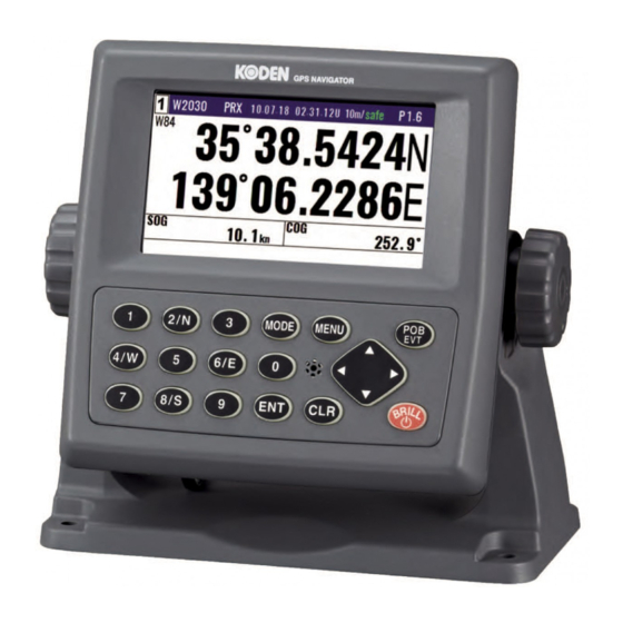
Chapter 1 Basic Operation KGP-922 1.4.3 Nav data display2 (NAV2) screen : Nav data2 mode Position in latitude and longitude Course Over Ground Speed Over Ground 1.4.4 Nav data display3 (NAV3) screen : Nav data3 mode Position in latitude and longitude... -
Page 21: Highway Display (Nav5) Screen : Highway Mode
KGP-922 Chapter 1 Basic Operation 1.4.6 Highway display (NAV5) screen : Highway mode XTE alarm range Position in latitude and longitude Course Over Ground Speed Over Ground Course Deviation Angle Cross Track Error 1.4.7 Plotter display (NAV6) screen : Plotter mode... -
Page 22: Storing Present Position (Event)
Chapter 1 Basic Operation KGP-922 1.5 Storing present position (EVENT) You can store up to 999 present positions with numbers 0001 to 0999. When you store additional positions, the oldest position is deleted and the newest position is stored in its place. -
Page 23: Changing The Setup Contents
KGP-922 Chapter 1 Basic Operation 1.5.3 Changing the setup contents (1) Press key until Menu options 1 to 10 appears. MENU key to select “10: Plotter”. (2) Press (3) Various settings 1) 1: Mark symbol ( Press key ) To change the Mark symbol, place cursor on SYMBOL option and press ENT key. -
Page 24: Using Pob (People Over-Board)
Chapter 1 Basic Operation KGP-922 1.6 Using POB (People over-board) POB function is provided for an emergency situation (if a person falls into the water) to make it easier to return to POB point. CAUTION POB key does not function when positioning is... -
Page 25: Copying Event And Pob Position
KGP-922 Chapter 1 Basic Operation P0000 is POB position data W0001~W0999 is Event position data W0999 1.8 Copying Event and POB position MENU (1) Press key until Menu options 1 to 10 appears. key to select “1: Waypoints” (2) Press (3) Enter storage number (0000 to 0999) by numeric keys and press key. - Page 26 Chapter 1 Basic Operation KGP-922 Press 1-10 0093130022-00...
-
Page 27: Chapter 2 Various Navigation
KGP-922 Chapter 2 Various Navigation Chapter 2 Various Navigation 2.1 Storing waypoints (LAT/LONG) data NOTE: Press to backspace the NOTE: Press to clear incorrect cursor to correct an input Input. You can reenter error. Numeric data. 2.1.1 Storing a new waypoint or updating an existing a waypoint Up to 5000 waypoints can be stored in memory. - Page 28 Chapter 2 Various Navigation KGP-922 Press Pop-up appear (6) Move the cursor to where you want to change. [Mark], [Latitude], [Longitude] or [Comment] Press [ ] key to move the cursor. Press (7) If you want to change the [Mark].
-
Page 29: Copying A Position
KGP-922 Chapter 2 Various Navigation 2.1.2 Copying a position You can copy the position data (stored with numbers 0000 to 4999) to the waypoint data (having numbers 1000 to 4999). (1) Press key until Menu options 1 to 10 appears. -
Page 30: Setup Of Waypoint Navigation
Chapter 2 Various Navigation KGP-922 2.2 Setup of waypoint navigation NOTE: Press to backspace the NOTE: Press to clear incorrect cursor to correct an input Input. You can reenter error. Numeric data. 2.2.1 Setting waypoint navigation The position data for each waypoint must be set prior to navigating to waypoints. You can use the data already stored from Menu, or you can set the waypoints on A (NAV1), B (NAV2), C (NAV3) or D (PLOT) screen (called the quick waypoint navigation). -
Page 31: Canceling Waypoint Navigation
KGP-922 Chapter 2 Various Navigation (2) Enter latitude and longitude. For example, if “N35°38.180 / E139°42.990” is inputted, a key will be pressed in order of [3],[5],[3],[8],[1],[8],[0],[N], [1],[3],[9],[4],[2],[9],[9],[0],[E]. (3) The waypoint is set and the point data is stored in number 4998. -
Page 32: Nav2 Screen During Waypoint Navigation
Chapter 2 Various Navigation KGP-922 2.2.4 NAV2 screen during waypoint navigation Alarm ANCH: Anchor watch alarm PRX: Proximity alarm XTE: Cross track error alarm CDI: Course deviation angle alarm Waypoint number Position in latitude and longitude Distance from present position from WPT... -
Page 33: Nav4 Screen During Waypoint Navigation
KGP-922 Chapter 2 Various Navigation 2.2.6 NAV4 screen during waypoint navigation Heading Line Own boat mark Latitude and Longitude of WPT Waypoint Distance from present position from WPT Bearing from present position from WPT Range ring Range Course Over Ground Speed Over Ground 2.2.7 NAV5 screen during waypoint navigation... -
Page 34: Nav6 Screen During Waypoint Navigation
Chapter 2 Various Navigation KGP-922 2.2.8 NAV6 screen during waypoint navigation Heading Line Own boat mark Latitude and Longitude Range of WPT Distance from present position from WPT Bearing from present position from WPT Waypoint Course Over Ground Route Waypoint... -
Page 35: Cross Track Error And Course Deviation Angle
KGP-922 Chapter 2 Various Navigation 2.3 Cross track error and course deviation angle 2.3.1 Navigation graph of NAV4 screen Use the navigation graph to check the distance and bearing to the waypoint. When the distance to WPT is further than the range (radius) of navigation graph, the WPT locates on the circle of navigation graph. -
Page 36: Highway Display (Nav5) Screen
Chapter 2 Various Navigation KGP-922 2.3.2 Highway display (NAV5) screen Use the three-dimensional chart for navigation on the course line. You can set a course width from Menu (6: Alerts). Symbol “ ” shows the waypoint, and your ship and track are shown along the course line. - Page 37 KGP-922 Chapter 2 Various Navigation (Nearing to the WPT) When you are close to the waypoint, the course line length decreases to 4 (nm, sm, km), 2 (nm, sm, km) and 1 (nm, sm, km). Then, the WPT marking closes to your ship.
-
Page 38: Storing And Erasing Routes
Chapter 2 Various Navigation KGP-922 2.4 Storing and erasing routes NOTE: Press to backspace the NOTE: Press to clear incorrect cursor to correct an input Input. You can reenter error. Numeric data. 2.4.1 Storing your route • Up to 100 routes and 500 waypoints can be registered for one route. -
Page 39: Automatic Switching Of Waypoints
KGP-922 Chapter 2 Various Navigation (9) If you want to change the [Waypoint] 1) Press key to select of the Input location of Waypoint 2) Enter a waypoint number (0000 to 4999) of the route by numeric keys. (You can check its memory data on the screen.) -
Page 40: Erasing Point Data
Chapter 2 Various Navigation KGP-922 Press 2.4.4 Erasing point data (1) Press MENU key until Menu options 1 to 10 appears. key to select “2: Routes”. (2) Press key to select “1: Route Set / Edit”. Route Input screen is displayed. -
Page 41: Route Setup
KGP-922 Chapter 2 Various Navigation (5) Press key to display the pop-up. (6) Select [Delete] in the pop-up and press key. (7) Press key to display the pop-up. (8) If OK, select [Yes] in the pop-up and press key. If Cancel, select [No] in the pop-up and press key. -
Page 42: Checking A Route Point Position
Chapter 2 Various Navigation KGP-922 (6) Select [Set] in the pop-up and press key. (7) You can select the first destination. In addition, you can be selected to Forward and Reverse. 1) Press [ ] key if you go Forward. -
Page 43: Canceling Route Navigation
KGP-922 Chapter 2 Various Navigation 2.5.3 Canceling route navigation To cancel waypoint navigation, turn Route to OFF on A (NAV1), B (NAV2), C (NAV3) or D (PLOT) screen. Cancel from [MENU] Cancel from NAV 1, NAV 2, NAV 3, NAV4, NAV5 or NAV6 screen. - Page 44 Chapter 2 Various Navigation KGP-922 ] key to display “T.RNG” “T.TTG”. (3) Press [ 2-18 0093130022-00...
-
Page 45: Setting An Anchor Position
KGP-922 Chapter 2 Various Navigation 2.6 Setting an anchor position After arriving at your destination, it is possible to drift from the anchor position due to a tide or wind. Once the anchor position is stored in memory, it is easy to check the distance and bearing moved from the anchor position. -
Page 46: Canceling Anchor Position
Chapter 2 Various Navigation KGP-922 Anchor mark Anchor position RNG: Distance from anchor position. BRG: Bearing from anchor position. 2.6.2 Canceling anchor position (1) Press MODE key until NAV1, NAV2, NAV3, NAV4, NAV5 or NAV6 screen appears. (2) Press key. -
Page 47: Track Display
KGP-922 Chapter 2 Various Navigation 2.7 Track display You can display track, the waypoint, course line, and cross cursor on the NAV6 screen. 2.7.1 Display a cross cursor on NAV6 screen You can display a cursor and position it on the screen. -
Page 48: Screen Scrolling
Chapter 2 Various Navigation KGP-922 2.7.2 Screen scrolling You can scroll the NAV6 screen in any direction so that your ship is always shown on the screen. If your ship moves off the screen, it will automatically return to the center of the display. - Page 49 KGP-922 Chapter 2 Various Navigation (3) Various settings 1) 1: Mark symbol (Press key) To change the Mark symbol, place cursor on SYMBOL option and press ENT key. Select symbol Press Key board cursor Initial setup: (Green) 2) 2: Mark display (Press key) You can select whether or not to display the Event mark information.
- Page 50 Chapter 2 Various Navigation KGP-922 5) 5: Track clear (Press key) You can delete the track according to color or all color. If you press the ENT key when the cursor is positioned at Track clear, the pop-up of select color will appear.
-
Page 51: Chapter 3 Alarms
KGP-922 Chapter 3 Alarms Chapter 3 Alarms 3.1 Kinds of alarms There are five kinds of alarms, anchor watch (ANCH), proximity (PROX), cross track error (XTE) and course deviation angle (CDI). 3.1.1 Anchor watch alarm (ANCH) An anchor watch alarm can alert you if your boat drifts a set distance from where it is activated. This alarm function will not work if the alarm range is set to "0.00". -
Page 52: Cross Track Error Alarm (Xte)
Chapter 3 Alarms KGP-922 Preset alarm range Blink Waypoint or route point Initial setup: ON, 1.00 Enter an alarm range: 0.00 to 9.99 3.1.3 Cross track error alarm (XTE) The cross track error (XTE) alarm alerts you when you have deviated from your course line by a predetermined distance. -
Page 53: Alarms Setting And Canceling
KGP-922 Chapter 3 Alarms 3.2 Alarms Setting and canceling (Setting alarm) MENU (1) Press key until Menu options 1 to 10 appears. key to select “6: Alerts”. (2) Press (3) Select item number of the alarm to be set by numeric keys. -
Page 54: Alerts
Chapter 3 Alarms KGP-922 3.3 Alerts Alerts are different from alarms. There is no setting on / off by the operator. It occurs when you should pay attention to or warn about system and operating conditions. There are three types of Alerts: Alarm, Warning, and Caution. -
Page 55: Alert Log
KGP-922 Chapter 3 Alarms 3.3.2 Alert Log You can check the date/time and the latitude/longitude of alert occurrence. The procedure is as follows: (1) Press key until Menu options 1 to 10 appears. MENU key to select “6: Alerts”. (2) Press key to select “5: Alert Log”. -
Page 56: Contents
Chapter 3 Alarms KGP-922 3.3.4 Alert list Priority Message Contents Caution HDOP exceeded The value of HDOP exceeded 4.0 Can not calculate position for more Warning No calculation of position than 5 minutes position been Warning Loss of position calculated for more than 1 s... -
Page 57: Chapter 4 Setup Procedure
KGP-922 Chapter 4 Setup Procedure Chapter 4 Setup Procedure 4.1 Menu options NOTE You can select an option from Menu in two ways: by direct numeric key entry or by cursor shifting. This manual explains how to enter numeric values for easy understanding, but you can also use the cursor for option selection. - Page 58 Chapter 4 Setup Procedure KGP-922 (4) Differential GPS (DGPS) Select DGPS style. Select DGPS mode. Set DGPS timeout. Select beacon station. Set beacon frequency. Select beacon bit rate. Set DGPS input baud rate. Monitor DGPS data. Monitor beacon message. (5) Compensation...
- Page 59 KGP-922 Chapter 4 Setup Procedure (8) Initial setup Set average constants. Select distance/speed units. Select antenna height (above sea level) units. Select navigation mode. Select position display mode (LAT/ LONG, LOPs). Select LAT/LONG display digits Set chain. (9) Interface Select output format. Edit the output format (IEC 61162-1). Select ACK/ALARM output (10) Plotter You can change the settings of [Plotter].
-
Page 60: Menu 3: Gps
Chapter 4 Setup Procedure KGP-922 4.2 Menu 3: GPS 4.2.1 Monitoring GPS satellite signal reception You can monitor the signal status from GPS (SBAS) satellites. The signals from 3 satellites are used for two-dimensional positioning, but signals from 4 or more satellites are required for three-dimensional positioning. -
Page 61: Selecting A Geodetic Datum
KGP-922 Chapter 4 Setup Procedure 4.2.3 Selecting a geodetic datum The latitude and longitude are calculated based on the WGS-84 with GPS system. However, the charts used in many countries are based on different geodetic datum. You can compensate this difference from your chart by converting GPS position data into your actual chart system. -
Page 62: Masking Satellite Elevation Angle
Chapter 4 Setup Procedure KGP-922 4.2.5 Masking satellite elevation angle When the satellite is below 5 degrees above the horizon, signal reflection and interference can cause erroneous positioning. You can improve the positioning accuracy by masking the elevation angle. However, a large mask value shortens the signal receive time and most satellite combinations are rejected. -
Page 63: Menu 4: Differential Gps (Dgps)
KGP-922 Chapter 4 Setup Procedure 4.3 Menu 4: Differential GPS (DGPS) This DGPS system can improve the GPS positioning accuracy. There are three styles, Auto and SBAS and Beacon. “BEACON” requires a signal from the external receiver system which outputs the compensation data of RTCM SC-104. -
Page 64: Setting A Dgps Timeout
Initial setup: 60 sec 4.3.4 Selecting a SBAS station KGP-922 can utilize the SBAS. Kind of receivable SBAS is WAAS, EGNOS, MSAS, GAGAN, SDCM, Other. There is an Auto function in the selection of SBAS. Auto function selects the nearest station. -
Page 65: Selecting A Beacon Station (Beacon Dgps Only)
KGP-922 Chapter 4 Setup Procedure Press Initial setup: PRN120 4.3.5 Selecting a beacon station (Beacon DGPS only) A beacon station is selectable in both the manual or auto mode. This mode is disable when “1: DGPS mode” is “SBAS” or “OFF”. -
Page 66: Selecting The Dgps Input Signal Baud Rate
Chapter 4 Setup Procedure KGP-922 Frequency Initial setup: 283.5 kHz Selectable range: 283.5 to 325.0 kHz Bit rate Initial setup: 200 bps 4.3.7 Selecting the DGPS input signal baud rate Adjust the baud rate of RTCM SC-104 format signal reception to the output signal baud rate of beacon receiver. -
Page 67: Beacon Monitor
KGP-922 Chapter 4 Setup Procedure 4.3.8 Beacon monitor DGPS monitor provides information on the DGPS beacon receiver interface and receiving status. MENU (1) Press key until Menu options 1 to 10 appears. key to select “4: DGPS”. (2) Press key to select “9: Beacon monitor”. -
Page 68: Menu 5: Compensation
Chapter 4 Setup Procedure KGP-922 4.4 Menu 5: Compensation 4.4.1 Correcting your position You can compensate your GPS present position given by GPS in the following two ways: • Enter the latitude and longitude of your actual position by numeric keys. -
Page 69: Disable Position Correction
If Cancel, select [No] in the pop-up and press key. 4.4.3 Compensating the LOP KGP-922 is converted from Latitude and Longitude to LoranC, LoranA and Decca. It can be corrected in the converted data. (Caution: Can not convert Decca LOP.) “2: LOP”... - Page 70 Chapter 4 Setup Procedure KGP-922 “2: LOP” To change the (1) Press key until Menu options 1 to 10 appears. MENU key to select “5: Compensation”. (2) Press key to select “2: LOP”. (3) Press (4) Enter the correct S1 and S2 value. The difference between the GPS position is reflected in the Correction offset when you enter the Actual position.
-
Page 71: Compensating The Compass
KGP-922 Chapter 4 Setup Procedure In the case of DECCA 4.4.4 Compensating the compass The course and bearing to waypoint is shown in true bearing. You can adjust the GPS true bearing to the magnetic compass bearing. (Automatic compensation) In the Auto mode, the magnetic compass is compensated based on the built-in global magnetic variation maps. -
Page 72: Displaying Local Time
Chapter 4 Setup Procedure KGP-922 Initial setup: 0.0 Setup range: -180.0° to +180.0° 4.4.5 Displaying local time You can display your local time by entering a time difference from the Greenwich Mean Time (GMT). See the following figure 4.1 to determine zone time difference. -
Page 73: Menu 7: Calculation
KGP-922 Chapter 4 Setup Procedure 4.5 Menu 7: Calculation 4.5.1 Calculating the distance and bearing between two points You can calculate the distance and bearing between two points stored in memory. (1) Press key until Menu options 1 to 10 appears. - Page 74 Chapter 4 Setup Procedure KGP-922 In the case of Loran C MENU (1) Press key until Menu options 1 to 10 appears. key to select “7: Calculation”. (2) Press key to select “2: L/L→LOP”. (3) Press (4) Enter (4-digit) Loran C chain number.
- Page 75 KGP-922 Chapter 4 Setup Procedure (12) Enter a (7-digit) latitude using numeric keys. (13) Enter “N” for north or “S” for south latitude. (14) Press key. (15) Enter (8-digit) longitude using numeric keys. (16) Enter “E” for east or “W” for west latitude.
-
Page 76: Calculating Navigation Plan
Chapter 4 Setup Procedure KGP-922 2-digit write If you store the calculation result. (1) Press [ ] key to display page 2/2. (2) Enter a data number (1000 to 4999) using numeric keys. (3) The existing data, if any, is displayed for your checkout. - Page 77 KGP-922 Chapter 4 Setup Procedure WPT number Boat speed : input item Press Time to go to Arrival time Waypoint Calculating boat speed and time to go to waypoint from WPT number and arrival time. MENU (1) Press key until Menu options 1 to 10 appears.
- Page 78 Chapter 4 Setup Procedure KGP-922 (6) Press [ ] key and enter a (3-digit) route number (001 to 100). (7) Press key. (8) Press [ ] key and press key to select Forward or Revers. (9) Press [ ] key and enter an (2-digit) origin waypoint number (01 to 500).
-
Page 79: Menu 8: Initial Setup
KGP-922 Chapter 4 Setup Procedure 4.6 Menu 8: Initial setup 4.6.1 Setting average constants (measuring position, speed and course) Use the averaging function to compare GPS sensor signals several times and get their average. This stabilizes the GPS position (latitude and longitude), speed and course data. The maximum averaging rate is “4”... -
Page 80: Changing Sail Mode
Chapter 4 Setup Procedure KGP-922 4.6.3 Changing sail mode You can change the navigation mode. There are two navigation modes. Great Circle course: ..the shortest course on a sphere. Rhumb Line course: ..straight course on a Mercator chart. -
Page 81: Changing The Latitude And Longitudinal Display Digits
4.6.6 Selecting GNSS source You can select the GPS source from Internal or External. If you select External, you can use KGP-922 as a remote indicator. At that time, connect external equipment to DATA2 connector, and input GGA / VTG / ZDA of NMEA sentence. -
Page 82: Selecting A Language
Chapter 4 Setup Procedure KGP-922 4.6.7 Selecting a Language You can select the language from the pop-up. The procedure is as follows: MENU (1) Press key until Menu options 1 to 10 appears. key to select “8: Initial setup”. (2) Press key to select “7:... - Page 83 KGP-922 Chapter 4 Setup Procedure In the case “LoranA” ] or [ ] key to move cursor onto the “LoranA”. (4) Press [ (5) Press key. ] key to move cursor onto the “9: Chain” and press (6) Press [ key.
-
Page 84: Menu 9: Interface
Chapter 4 Setup Procedure KGP-922 4.7 Menu 9: Interface 4.7.1 Selecting a DATA port and NETWORK port to setting. NETWORK DATA1 DATA2 You can select the format of output data. (1) Press MENU key until Menu options 1 to 10 appears. -
Page 85: Setting The Baud Rate
KGP-922 Chapter 4 Setup Procedure You can select from three formats. 1) IEC61162-1 2) NMEA0183 Ver3.0 3) NMEA0183 Ver2.0 In the case “DATA2” of “1: Connector” ] key to move cursor onto the output data format to select “DATA2”. (4) Press [... -
Page 86: Setting The Output Talker Id
Chapter 4 Setup Procedure KGP-922 4.7.4 Setting the output Talker ID You can change the Talker ID “GP” only or System dependent (“GP”, “GL” and “GN”) MENU (1) Press key until Menu options 1 to 10 appears. key to select “9: Interface”. -
Page 87: Setting The Sentence To Output To Ethernet
KGP-922 Chapter 4 Setup Procedure Press (4) Press [ ], [ ], [ ] or [ ] key to select the output sentence. (5) Press numeric keys to change output interval. Set 00 if you want to stop output. * Bar meter at the bottom of screen is the occupancy rate of the NMEA. Please set to be 100% or less. -
Page 88: Setting The Ip Address
Chapter 4 Setup Procedure KGP-922 4.7.8 Setting the IP Address Set the IP Address and Subnet mask, Default gateway. MENU (1) Press key until Menu options 1 to 10 appears. key to select “9: Interface”. (2) Press key to select “7: Ethernet”. -
Page 89: Setting The Sfi
KGP-922 Chapter 4 Setup Procedure (7) Press key. A pop-up will be displayed. (8) Please turn off the power and restart it. NOTE: Even when it is "ON", if the DHCP server etc is not working, it will operate with local IP. -
Page 90: Ethernet (Special)
Chapter 4 Setup Procedure KGP-922 key to select “8: Ethernet (SYSLOG)”. (3) Press Press (4) Press key. (5) Select [YES] in the pop-up and press key to clear the SYSLOG error count. If clear cancel, select [No] in the pop-up and press ENT key. -
Page 91: Chapter 5 How To Use Lops
KGP-922 Chapter 5 How to use LOPs Chapter 5 How to use LOPs 5.1 Initial setup for LOPs display Measured longitude and latitude can be translated into loran C, loran A or DECCA. To turn on the LOPs mode, the following initial setup is required. - Page 92 Chapter 5 How to use LOPs KGP-922 Secondary station 1 Secondary station 2 In the case “LoranA” (4) Press [ ] or [ ] key to move cursor onto the “LoranA”. (5) Press key. ] key to move cursor onto the “9: Chain”.
- Page 93 KGP-922 Chapter 5 How to use LOPs When select Auto mode, KGP-922 finds the optimal station If you select “Manual” (9) Input the station of DECCA by numeric keys. (10) Press [ ] key. ] key. You can select “RG”, “RP” or “GP”.
-
Page 94: Storing Waypoints (Lops Data)
Chapter 5 How to use LOPs KGP-922 5.2 Storing waypoints (LOPs data) NOTE: Press to backspace the NOTE: Press to clear incorrect cursor to correct an input Input. You can reenter error. Numeric data. 5.2.1 Storing a new position or updating an existing one Up to 5000 waypoints can be stored in memory. -
Page 95: Compensating The Lop
• "Erasing a single waypoint" (See page 2-3) 5.3 Compensating the LOP KGP-922 can be converted from Latitude and Longitude to LoranC, LoranA and DECCA. It can be corrected in the converted data. For the following operations, refer to 4.4.3 "Compensating the LOP"... - Page 96 - This page intentionally left blank.-...
-
Page 97: Chapter 6 Data Backup And Initialization
KGP-922 Chapter 6 Data backup and Initialization Chapter 6 Data backup and Initialization 6.1 Data backup You can back up the waypoint/route data and setting values by USB memory. 6.1.1 Displaying the “Data backup” menu The procedure is as follows: (1) Press key and Power ON. -
Page 98: Writing Of Data
Chapter 6 Data backup and Initialization KGP-922 Press In the case “Read out of setting values” (1) Press [ ] or [ ] key to move cursor onto the “Read out of setting values”. (2) Press key. (3) Select “Yes” in the pop-up and press key. - Page 99 KGP-922 Chapter 6 Data backup and Initialization In the case “Writing of setting value” *The data file is necessary in USB memory named “KM-F81_SETUP.dat”. (1) Press [ ] or [ ] key to move cursor onto the “Writing of setting value”.
-
Page 100: Initialization
Chapter 6 Data backup and Initialization KGP-922 6.2 Initialization When some malfunction of Display unit is found, following initialization procedure may be required. It returns all the settings in the menu to the factory settings. 6.2.1 Displaying the “Initial menu”... -
Page 101: Wpt./Route Clear
KGP-922 Chapter 6 Data backup and Initialization 6.2.3 WPT./Route clear You can erase the entire data such as waypoints, events, POB, and routes from internal memory. (1) Press [ ] or [ ] key to move cursor onto the “WPT. / Route clear”. -
Page 102: Selecting An Initial Value (North, South, East, West) Of Latitude/Longitude
Chapter 6 Data backup and Initialization KGP-922 6.2.5 Selecting an initial value (North, South, East, West) of latitude/longitude. N/W (N. Lat./W. Long.): When editing a waypoint, GPS position is started using the north latitude/west longitude region as the initial value. -
Page 103: Setup Own Ship Outline
KGP-922 Chapter 6 Data backup and Initialization 6.2.8 Setup own ship outline Set up own ship outline and antenna position from CCRP (Consistent common reference point). Press This setup is to designate ship’s outline and antenna location of CCRP. Set the width and length of your ship. Enter the values as correct as possible because these values influence the output sentence "POS". - Page 104 - This page intentionally left blank.-...
-
Page 105: Chapter 7 Installation
Chapter 7 Installation Chapter 7 Installation 7.1 Installation consideration Qualified service technicians should perform the installation of the KGP-922 series that comprises the following operations. (1) Unpacking each component of the system. (2) Inspection of the exterior of each component unit and accessory. -
Page 106: Siting The Units
(4) Reset the Display unit on to the bracket and fix it using the two knurled fixing knobs that were removed in step (1). Refer to Figure 7.1 for detail. Unit: mm (inch) Figure 7.1 Fitting detail of KGP-922 in table mounting mode 0093130022-00... - Page 107 KGP-922 Chapter 7 Installation Unit: (inch) Figure 7.2 Maintenance space required for KGP-922 Unit: mm (inch) 0093130022-00...
-
Page 108: Flush Mounting
Chapter 7 Installation KGP-922 7.4.2 Flush mounting (1) Cut a rectangle opening as shown in a figure 7.3. (2) Loosen two fixing knobs that fasten the Display unit onto the mounting bracket. (3) Insert a coin in the two gaps at the lower part of the Display unit and remove the front frame. -
Page 109: Antenna Unit Installation
KGP-922 Chapter 7 Installation 7.5 Antenna unit installation 7.5.1 Selecting the best site of GPS / Beacon antenna Make sure to install the Antenna unit at a location where nothing shades the antenna of a view above the horizon. Objects placed above the Antenna unit or too close to the Antenna unit may cause signal to noise ratio to degrade and shorten measuring time. -
Page 110: Fixing The Gps Antenna Unit
Chapter 7 Installation KGP-922 7.5.2 Fixing the Antenna unit (Case1) (Case2) Antenna unit Antenna unit GA-09(IMO)[15M] GA-09(IMO)[15M] GA-09(IMO)[0.5M] GA-09(IMO)[0.5M] Hose clamp (Option) Screw (1”-14UNS-2B) Antenna Mast (pole) extension pole (not supplied) (not supplied) Installation precautions (1) Adhesive plastic sealant or silicone for plastic is recommended for fixing screws. -
Page 111: Extension Of An Antenna Cable
KGP-922 Chapter 7 Installation 7.5.3 Extension of an antenna cable Although the standard length of an antenna cable is 15m, extension of 30m or 60m is possible by the antenna and extension cable of an option. GA-09(IMO)[0.5M] Waterproofing required Conversion Cable Assy 0.5m... -
Page 112: Cable Connections To Kgp-922
Chapter 7 Installation KGP-922 7.6 Cable connections to KGP-922 7.6.1 Single connection Legend Standard configuration Option Owner supply Antenna unit GA-09(IMO) Display unit KGP-922 With mounting bracket and cover Ethernet equipment DATA 2 Connector Beacon receiver CW-376-5M DATA 2 Connector... -
Page 113: Multi Connections
KGP-922 Chapter 7 Installation 7.6.2 Multi connections Legend Standard configuration Option Owner supply Antenna unit GA-09(IMO) Display unit KGP-922 With mounting bracket and cover Ethernet equipment DATA 2 Connector Beacon receiver CW-376-5M DATA 2 Connector CW-373-5M Marine radar Chart Plotter... -
Page 114: Connector Pin Outs
Chapter 7 Installation KGP-922 7.7 Connector pin outs NETWORK POWER 1: TX (+) 2: RX (+) 3: TX (-) 4: RX (-) 1: F.GND 2: DC + 3: DC - (General data output) DATA 2 DATA1 1: GND/SHIELD 1: GND/SHIELD... - Page 115 KGP-922 Chapter 7 Installation CW-426 cable 1 male connector M12 4 straight D coding 1 Female connector RJ45 straight 0093130022-00 7-11...
-
Page 116: Inspection After Installation
Chapter 7 Installation KGP-922 7.8 Inspection after installation Before you turn the unit on, check the following points to make sure the system operates properly. (1) Is the ship’s supply voltage and current within the rated range? (2) Is the connection between the Display and Antenna unit correct? -
Page 117: Chapter 8 Specifications
KGP-922 Chapter 8 Specifications Chapter 8 Specifications 8.1 Specification 8.1.1 Main function Receiving frequency 1575.42 MHz±1MHz Receiving channel 72 channel parallel Receiving code C/A code Better than –148 dBm Sensitivity Accuracy Position 4.2 m 2drms(GPS), 3.3 m 2drms(DGPS) 0.1 kt rms... -
Page 118: Power Requirements
Chapter 8 Specifications KGP-922 8.1.2 Power requirements Input voltage: 10.8 to 31.2 VDC Power consumption: Less than 6 W (at 24VDC) AC Operation: AC/DC rectifier PS-010 is required. Input voltage range: 115 VAC or 230 VAC 8.1.3 Compass safe distance Standard: 0.6m... -
Page 119: External Dimensions And Weight
KGP-922 Chapter 8 Specifications 8.2 External dimensions and weight 8.2.1 External dimensions and weight of the Display unit: KGP-922.MU External dimensions: Width x Height x Depth Dimensions (WxHxD): 174 x 165 x 98 (mm) Weight: 0.97 kg Unit: mm 8.2.2 External dimensions and weight of the Antenna unit: GA-09... - Page 120 - This page intentionally left blank.-...
-
Page 121: Chapter 9 Maintenance And Troubleshooting
KGP-922 Chapter 9 Maintenance and Troubleshooting Chapter 9 Maintenance and Troubleshooting 9.1 Periodic inspection and cleaning 9.1.1 Monthly check Check if there is any loose connection on the Processor unit for GPS Antenna, radar or navigational unit. 9.1.2 Maintenance If the display unit is smeared or stained with dirt, wipe the surface of the unit with soft dry cloth. - Page 122 Chapter 9 Maintenance and Troubleshooting KGP-922 Symptom Possible cause of trouble Measure Unstable signal reception 1. Are the connections between the 1. Check the connection and GPS antenna and the display unit reconnect, if necessary. is correct and firm? 2. Is there any obstacle preventing 2.
-
Page 123: Chapter 10 Technical Reference
KGP-922 Chapter 10 Technical Reference Chapter 10 Technical Reference 10.1 Input data format RTCM SC-104 Ver 2.0 (DGPS) *Baud rate: 4800/9600/19200/38400, DATA2 connector only. ACN sentence *Baud rate: 4800/9600/19200/38400, DATA1 and DATA2 connector. Sentences ACN, and ALC, /ALF are used for alert handling. -
Page 124: Output Sentence
Chapter 10 Technical Reference KGP-922 10.4 Output sentence Description Contents of data field Waypoint arrival alarm $ GP AAM, A, A, x.x, N, c--c*hh <CR><LF> Waypoint ID Units of radius, nautical miles Arrival circle radius A = Perpendicular passed at waypoint... - Page 125 KGP-922 Chapter 10 Technical Reference Description Contents of data field Set alarm state $--ALR,hhmmss.ss,xxx,A,A,c--c*hh<CR><LF> Alarm's description text A = acknowledged V = unacknowledged A = threshold exceeded V = not exceeded Unique alarm number (identifier) at alarm source Time of alarm condition change, UTC Heading / track contoroller (autopoilot) sentence B $--APB,A,A,x.x,a,N,A,A,x.x,a,c--c, x.x,a,x.x,a,a*hh<CR><LF>...
- Page 126 Chapter 10 Technical Reference KGP-922 Description Contents of data field Bearing and distance to waypoint $--BWC, hhmmss, llll.lll, a, yyyyy.yyy, a, x.x, T, x.x, M, xx, N, c--c, a*hh<CR><LF> Mode indicator A: Autonomous D: Differential N: Data not valid Waypoint ID...
- Page 127 KGP-922 Chapter 10 Technical Reference Description Contents of data field GPS satellite fault detection $--GBS, hhmmss.ss, x.x, x.x, x.x, x.x, x.x, x.x, x.x, h, h*hh<CR><LF> GNSS Signal ID GNSS System ID Standard deviation of bias estimate Estimate of bias on most likely failed satellite...
- Page 128 Chapter 10 Technical Reference KGP-922 Description Contents of data field Geographic position – Latitude/longitude $--GLL, xxxx.xxx, N/S, xxxxx.xxx, E/W,hhmmss , a *hh <CR><LF> Status Longitude Latitude A: Valid V: Void Fix measurement time elapsed (Hour, Min, Sec) N: North latitude...
- Page 129 KGP-922 Chapter 10 Technical Reference Description Contents of data field MSK receiver signal status $--MSS,,x.x,x.x,x.x,x*hh<CR><LF> Channel number Beacon bit rate (25, 50, 100, 200) bit/s Beacon frequency, 283,5 kHz to 325,0 Signal to noise ratio (S/N),dB This field is not use Recommended minimum navigation information $--RMB, A, x.x, a, c--c, c--c, llll.lll, a, yyyyy.yyy, a, x.x, x.x, x.x, A, a*hh<CR><LF>...
- Page 130 Chapter 10 Technical Reference KGP-922 Description Contents of data field Routes *Maximum of four Waypoints are outputted $--RTE, x.x, x.x, a, c--c, c--c, …... c--c*hh <CR><LF> Waypoint “n” identifier Additional waypoint identifiers Waypoint identifier Route identifier C = complete route, all waypoints W = working route, first listed waypoint is “FROM”,...
- Page 131 KGP-922 Chapter 10 Technical Reference Description Contents of data field Cross-track error, measured $--XTE,A,A,x.x,a,N,a*hh<CR><LF> A = Autonomous mode D = Differential mode E = Estimated (dead reckoning ) mode M = Manual input mode S = Simulator mode Units, nautical miles...
-
Page 132: Input / Output Circuit
Chapter 10 Technical Reference KGP-922 10.5 Input / Output circuit Port (connector) name: DATA1, DATA2 The connector used: BD-06PMMP-LC7001 (DATA port Input circuit) Input load: 470 ohm Device: Photo-coupler ACPL-M61L (Avago) +3.3V ACPL-M61L RXD (+) RXD (-) (DATA port output circuit) -
Page 133: Chapter 11 Annex
KGP-922 Chapter 11 Annex Chapter 11 Annex 11.1 Menu configuration The factory set value is shown by the surrounding boxes. MENU 1: Waypoints 2: Routes 1: Route Set / Edit 2: Waypoint change (Circle, Bisector) 3: GPS 1: GPS monitor... - Page 134 Chapter 11 Annex KGP-922 8: Initial setup 1: Averaging (0, 1, 2, 3, 4) 2: Units (NM, km, sm) 3: Sailing mode (Great circle, Rhumb Line) 4: Position (L/L, Lop) 5: L/L units (.001, .0001) 6: GPS source (Internal, External)
-
Page 135: Local Geodetic Systems
KGP-922 Chapter 11 Annex 11.2 Local Geodetic Systems The number assigned to each place name is the set values used in the “Selecting a geodetic datum” (Page 4-5) Name Name Name ALASKA / CANADA FLORIDA PHOENIX ARC 50 GREENLAND PITCAIRN...
Need help?
Do you have a question about the KGP-922 and is the answer not in the manual?
Questions and answers