Advertisement
Quick Links
Advertisement

Related Manuals for Extreme Flight EXTRA260


Summary of Contents for Extreme Flight EXTRA260
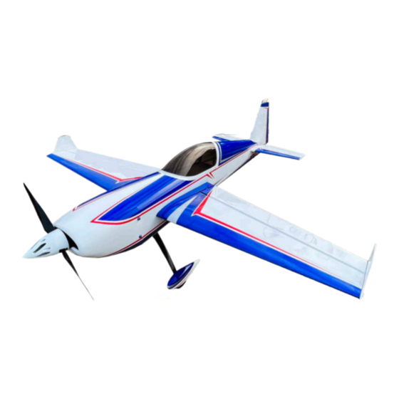
- Page 1 67” / 1.7M 8lbs / 3.6 Kg T-motor AM670 6s 4000-5000mah ARF ASSEMBLY GUIDE www.modellmarkt24.ch...
- Page 2 Extreme Flight RC guarantees this kit to be free of defects in materials and workmanship for a period of 30 DAYS from the date of purchase. All warranty claims must be accompanied by the original dated receipt. This warranty is extended to the original purchaser of the aircraft kit only.
- Page 3 Installing control horns: All of the control horns on your aircraft install in the same way. Locate the correct control horn for each surface. Prep the horns by lightly scuffing the gluing area (the part which will go into the control surface) with sandpaper or an emery board. Test fit the horn and cover plate without glue to make sure it goes all the way into the surface as shown.
- Page 4 Installing main landing gear: Attach the carbon landing gear to the fuselage with screws as shown, use blue Loctite (or other medium-strength threadlocker) on these screws. Note that there is a “front” to the landing gear and when installed, they sweep slightly forward. Locate the fairings, test fit them, and then premanently attach them to the landing gear (not the fuselage) using a generous amount of “Goop”...
- Page 5 Installing the horizontal stab and elevators: Test fit the stabilizer without glue. Make sure it fully inserts into the fuselage as shown. Make sure you have it right-side-up. When you have the sta- bilizer perfectly fitted, glue it in place with thin CA glue as shown. Clean up any spilled CA with acetone.
- Page 6 The rudder is retained with a wire. Place the rudder in position and install the wire from the bottom as shown. www.modellmarkt24.ch...
- Page 7 Install the tailwheel as shown using hex-head wood screws. Install the phillips-head wood screw as shown into the rudder to hold the tailwheel tiller. Make sure the tailwheel can easily swing with the rudder. The tailwheel assembly retains the rudder hinge wire in place. www.modellmarkt24.ch...
- Page 8 Attach servo wire extensions to your servos and use tape or a wire lock to make sure they do not be- come disconnected in flight. Install the servos in the positions and orientations shown. Center your servos using your radio or a servo tester, then install your arms. Install the linkage as shown using screws, washers , locking nuts, and tapered spacers as shown.
- Page 9 The 67” Extra 260 is configured for easy installation of the T-motor AM670 power system. Oth- er systems will install similarly. Mount the motor X-mount to the firewall as shown, use Loctite. Attach the motor to the X-mount as shown. Mount the ESC to the mounting pad on the bottom of the motor box with zip-ties as shown.
- Page 10 Attach the cowl to the fuselage with screws, use loctite. Here we have added optional Extreme Flight decorative aluminum washers. Adjust and tighten the prop mount and make sure you have a small amount of clearance (approx 2mm) between the spinner backplate and cowl. NOTE: if you are new to high performance aerobatic aircraft, your motor points 2.5 degrees to the RIGHT to balance torque and prop forces.
- Page 11 Install your receiver in the position shown. If using the T-Motor power system, install the power capacitor into any open channel of your receiver as shown. We prefer to use dou- ble-sided foam tape and a zip-tie to mount our receivers. Install your lipo battery and two strong velcro straps as shown.
- Page 12 We prefer to use a cell phone with an angle-finder app as a control throw guage, but any accurate gauge is fine. Set your control throws as recommended below. We have recommended high expo for your maiden flight; if you have a favorite expo value you typically run on 3D aircraft, use it.
- Page 13 YouTube, which has a detailed section on covering maintenance and many other tips. If you need to repair your Extra 260, spare parts are available from your Extreme Flight dealer, and col- or-matched covering is available in either the Oracover or Ultracote systems.
Need help?
Do you have a question about the EXTRA260 and is the answer not in the manual?
Questions and answers