Advertisement
Quick Links
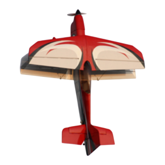
Assembly Manual / Airframe – 42" VyperBype
Thank you for purchasing this 3DHobbyShop by Extreme Flight ARF RC aircraft. If you have
any issues, questions, concerns or problems during assembly, please contact our tech
department at: Info@extremeflightrc.com or 770-887-1794 10am-5pm Eastern Monday thru
Friday.
SAFETY in Assembly
During assembly of this aircraft, you will be asked to use sharp knives and hobby adhesives.
Please follow all safety procedures recommended by the manufacturers of the products you use,
and always follow these important guidelines:
ALWAYS protect your eyes when working with adhesives, knives, or tools, especially power
tools. Safety glasses are the best way to protect your eyes.
ALWAYS protect your body, especially your hands and fingers when using adhesives, knives,
or tools, especially power tools. Do not cut toward exposed skin with hobby knives. Do not
place hobby knives on tables or benches where they can roll off or be knocked off.
ALWAYS have a first-aid kit handy when working with adhesives, knives, or tools, especially
power tools. ALWAYS keep hobby equipment and supplies out of the reach of children.
SAFETY in Flying
This is NOT a toy! It is a very high-performance RC airplane capable of high speeds and
extreme maneuvers. It should only be operated by a competent pilot in a safe area with proper
supervision.
ONLY fly your aircraft in a safe, open area, away from spectators and vehicles and
where it is legal to fly. NEVER fly over an unsafe area, such as a road or street.
NEVER fly near overhead power or utility lines. If your airplane ever becomes stuck in
a line or a tree DO NOT attempt to retrieve it yourself. Contact the authorities for
assistance in retrieving your aircraft. Power lines are DANGEROUS and falls from
ladders and trees CAN KILL!
Never fly too close to yourself or spectators.
Spinning propellers are DANGEROUS!
Never run your motor inside a house or building with the propeller attached Remove the
prop for safety. Always fly within your control.
Always follow manufacturers instructions for your radio system.
Always preform a pre-flight check of your aircraft to be certain of the aircraft's
airworthiness.
A lways obtain proper insurance before flying. Always fly model aircraft in accordance
with the Academy of Model Aeronautics (AMA) Safety Code. Visit the AMA's website
at
www.modelaircraft.org
for more information.
1
Advertisement

Related Manuals for Extreme Flight 42 Vyper Bype


Summary of Contents for Extreme Flight 42 Vyper Bype
- Page 1 Assembly Manual / Airframe – 42” VyperBype Thank you for purchasing this 3DHobbyShop by Extreme Flight ARF RC aircraft. If you have any issues, questions, concerns or problems during assembly, please contact our tech department at: Info@extremeflightrc.com or 770-887-1794 10am-5pm Eastern Monday thru Friday.
-
Page 2: Limits Of Responsibility
Extreme Flight provides high-quality aircraft and components to it's customers and end users. These aircraft and components are assembled by the end user to produce a flying model. It is beyond Extreme Flight's control to monitor the end user's completed aircraft. Therefore, Extreme Flight in no way accepts or assumes responsibility or liability for damages resulting from the end user assembled product. -
Page 3: Let's Get Started
natural property of balsa wood. As your airplane adjusts to the weather in your part of the world, wrinkles may appear and disappear. Wrinkles may be removed with the gentle application of heat to the covering material on your airplane. The best tools to use are a heat gun and covering iron. Apply the heat gently: the covering material will shrink as you apply the heat, and this will remove the wrinkles. - Page 4 Assembly Assemble cradle from bare wood pieces as shown using CA glue. Use the cradle to support the aircraft for assembly and later for battery changes at the flying field.
- Page 5 Start by sliding the wheels onto the aluminum wheel axles, and tightening the aluminum wheel collars with a 1.5mm hex driver. Slide the wheels and axles into the wheel pants as shown.
- Page 6 Attach the wheel pant assembles onto the carbon main landing gear with 4mm locknuts as shown. Hold the wheel collars with needle-nose pliers while tightening the nuts. Screw wood screws into the pants as shown, going about half-way in. Then, remove the screws and clip off about ½...
- Page 7 Remove covering over control-horn slot and tail-wheel slotin rudder as shown, using a hobby knife or hot soldering iron. Slide double-sided rudder control horn into slot in rudder as shown, drip several drops of thin CA into the slot to attach horn.
- Page 8 Assemble tailwheel onto tailwheel wire with collar as shown. Install bracket onto tailwheel wire as shown and glue tailwheel into bottom of rudder with epoxy, polyurethane, or thick CA adhesive.
- Page 9 Slide rudder onto fin and glue hinges with a few drops of thin CA each. Install wood screws through holes in tailwheel bracket to attach tailwheel to fuselage. NOTE: check rudder swing after installing screws. If tailwheel bracket causes rudder to become stiff and you do not see an easy fix, remove the rearmost screw in the bracket.
- Page 10 Apply masking tape as shown to rudder and fin to hold rudder straight. Assemble the rudder servo arm as shown. The connector nuts should be loose enough to allow the connectors to rotate freely on the horn, use medium CA glue to lock the nuts into place permanently. Note that we are using DuBro #672 arms in these photos.
- Page 11 Install rudder servo into fuselage as shown. Please study the pull-pull cable diagram. Assemble the front ends of the cables as shown. Make the loop in the cable as shown before crimping. Crimp the brass tube sleeve with pliers to secure the assembly. Crimp HARD to keep the cable from sliding, then add a drop of thin CA to the crimp-joint.
- Page 12 Install the cables into the rudder servo arm as shown. Assemble the rudder end of the cables. The cables should cross once inside the fuselage forming an "X" shape. Be sure to use CA glue on the nuts holding the ball links to the rudder arm.
- Page 13 Remove covering over horizontal stab opening on both sides of the fuselage. Remove covering over the elevator servo location on the left side of the fuse only. Remove covering over wing spar tube opening, wing bolt holes, wing alignment pin holes and aileron servo wire opening as shown, on both sides of fuselage.
- Page 14 Insert the carbon wing spar tube into the fuselage. Insert the horizontal stabilizer into its slot. Check the stab for level against the tube. Adjust as necessary by sanding the slot. Use a ruler to center the stab side-to-side, and front-to-back on each side; check all alignments of the stab carefully. When you are satisfied with the stab alignment, place several drops of thin CA glue into the joint of the stab and fuselage, allow to wick into the joint.
- Page 15 Install elevators onto horizontal stab. Apply several drops of thick or medium CA into the slot on one elevator half before installing onto the joiner rod of the other elevator half. Install elevator control horn. Assemble elevator pushrod as shown and install on horn, using CA glue to lock the nut.
- Page 16 Run elevator servo wire forward in fuselage and install elevator servo/arm as shown. Be sure to use CA to lock the nut on the pushrod connector, but still allowing it to rotate. Install your brushless motor to firewall as shown. Note that in order to balance properly, the Vyper Bype needs a brushless outrunner motor approx 170-200g.
- Page 17 Install your esc into the front of the fuselage as shown. Place pieces of masking tape over the plywood cowl mounting pads in the fuselage sides as shown. Slide the cowl onto the fuselage and center as shown.
- Page 18 Use tape strips to locate the plywood mounting pads and drill holes for small wood screws. Install wood screws to retain cowl as shown.
- Page 19 Attach velcro and seatbelt for lipo to the battery tray as shown. NOTE: There's not a lot of room inside the fuselage. You will need to attach the receiver to the fuselage side where it does not interfere with the rudder servo, and tie up all servo wires close to the fuselage sides.
- Page 20 Being a biplane, the Vyper Bype uses 4 wing halves. The lower 2 house the aileron servos. The ailerons of the upper and lower wings are connected by wire pushrods. Assemble the 4 aileron interconnecting arms as shown with servo connectors. The aileron interconnecting arms mount through slots in the trailing edge of the ailerons.
- Page 21 Mount the interconnect arms with CA glue as shown. Assemble aileron servos, pushrods, and arms as shown.
- Page 23 Install lower wings with wing bolts as shown.
- Page 24 Use thin CA to strengthen the tabs on the wings. Allow to dry completely. Use bolts, washers, and locking nuts to attach struts to lower wing as shown.
- Page 25 Make sure carbon rod anti-rotation pin is installed into upper wing half as shown.
- Page 26 Slide upper wing spar tube into center (cabane) wing strut, slide upper wings on. Use bolts, washers, and locking nuts to attach wing struts to upper wings as shown. NOTE: These screws are intended to be installed permanently. When removing the wings for transport, we recommend removing both left wings together, and both right wings together, and sliding them onto their carbon tubes all together for transport as a unit.
- Page 27 Use masking tape on the trailing edges of both ailerons to hold them straight to the wing trailing edges as shown. Install the long wire interconnect rods as shown and tighten the connector screws.
- Page 28 Using clear tape, CA glue, or Welder's Glue, install the balsa wood landing gear fairings to landing gear legs as shown. NOTE: the fairings do affect the flight characteristics and you should install them. Setting CG Balance the Bype by supporting the upper wing with your fingertips. The balance point is 5 1/8" to 5 1/4" back from the front of the upper wing at the center.
- Page 29 Control Throws Ailerons: Low 15 degrees High 30 degrees Elevator: Low 15 degrees High 45-50 degrees Rudder: Low 10 degrees High 25 degrees Use Exponential on all controls. We recommend starting with 25% on low rates and 60% on high rates. Adjust as needed to obtain the control feel you want.
Need help?
Do you have a question about the 42 Vyper Bype and is the answer not in the manual?
Questions and answers