
Related Manuals for Marshall Electronics V-MD173


Summary of Contents for Marshall Electronics V-MD173
-
Page 1: Operating Instructions
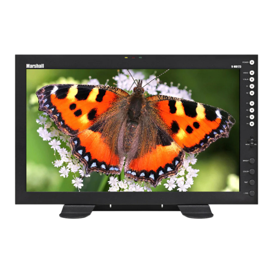
Marshall Electronics V-MD173 Model No. Rack Mountable High Definition LCD Monitor Operating Instructions Edition 1 Revision 7W... - Page 2 Page Intentionally Left Blank...
-
Page 3: Table Of Contents
Table of Contents Installation and Initial Setup ------------------------------------------------------------------------------------------------------5 Top and Front Panel Features ----------------------------------------------------------------------------------------------------6 Rear Panel Features-----------------------------------------------------------------------------------------------------------------7 Compatible Input Formats---------------------------------------------------------------------------------------------------------8 Input Module Installation----------------------------------------------------------------------------------------------------------9 MAIN MENU AND NAVIGATION------------------------------------------------------------------------------------------------ 11 VIDEO CONFIGURATION SUBMENU..............................11 MARKER CONFIGURATION SUBMENU ..............................14 FILTER CONFIGURATION SUBMENU..............................17 SYSTEM CONFIGURATION SUBMENU ..............................19 FUNCTION PRESETS SUBMENU ................................20 IMD &... - Page 4 Page Intentionally Left Blank...
-
Page 5: Installation And Initial Setup
■ The V-MD173 can be mounted in any standard EIA 19” equipment rack. The attached rack ears can be angled to provide the user control over the viewing angle. Adequate ventilation is required when installed to prevent possible damage to the monitor’s internal components. -
Page 6: Top And Front Panel Features
Top and Front Panel Features Image Adjustment Knobs Power Button Use the image adjustment knobs to adjust color brightness, Use the power button to toggle between ON and STANDBY color-saturation, tint, and contrast of the image. The status of modes. In both the STANDBY and the ON state, the LED on each image adjustment parameter is shown on the bottom left the button will illuminate bright green. -
Page 7: Rear Panel Features
Rear Panel Features YPbPr and CVBS Video Input and Output Desktop Mounting Holes The V-MD173 has CVBS and YPbPr inputs and one active loop- These holes are used when attaching the monitor to the through output for each input. See Compatible Input Formats optional desktop stand. -
Page 8: Compatible Input Formats
Compatible Input Formats The following video standards are supported by the V-MD173: Video Input NTSC, PAL YPbPr Input 480i, 576i/50 480p, 576p/50 720p/25, 29.97, 30, 50, 59.94, 60 1080p/23.98, 23.98sF, 24, 24sF 1080i/50, 59.94, 60 Optional Input Modules (Type A modules) MD-3GSDI and MD-TC –... - Page 9 Page Intentionally Left Blank...
-
Page 10: Input Module Installation
Input Module Installation 1. Remove Power From Unit Modules are cold-swappable only. Damage will occur if modules are inserted or removed while unit is powered. 2. Remove Blank Module Cover Using Philips screwdriver, remove the 4-40x1/8” screws. There are a total of three screws, save them for later use. -
Page 11: Main Menu And Navigation
MAIN MENU AND NAVIGATION Access the main menu by pushing and holding the MENU button on the front panel of the monitor. •Step through menu items using the ▲ and ▼ buttons. •Choose a submenu or select a menu item by pressing SELECT. •Return to the previous menu by pressing MENU. -
Page 12: Color Temperature
Color Temperature ■ Use this setting to choose one of three color temperature presets: • D55 (5500K) • D65 (6500K) • 9300K • USER (Adjustable Color Bias and Gain) • Linear (No processing is applied to the panel) Use this setting to enable monochrome mode. Only the luminance of the image will be displayed as a grayscale picture. Gamma ■... - Page 13 Use the check field modes for monitor calibration or to analyze individual color components of an image. In Monochrome mode, all color is disabled and only a grayscale image is shown. In Blue, Green, and Red check field modes, only the selected color will be shown.
-
Page 14: Marker Configuration Submenu
Note: The aspect ratio setting is ignored when Pixel-to-Pixel mode is enabled. ■ Pixel-to-Pixel Use this setting to enable Pixel-to-Pixel mode. This Pixel-to-Pixel mode bypasses the monitor’s internal scaling function and displays incoming images in their native resolution and aspect ratio, with a one-to-one mapping: •... - Page 15 Use this setting to enable or disable all on-screen markers. This setting affects the center marker, full screen markers, 16:9 markers and 4:3 markers. ■ Center Marker Use this setting to display a center marker on the screen. ■ 16:9 Markers Use these settings to superimpose one of 12 markers on the screen when in 16:9 mode.
- Page 16 • 85% Safe Area • 80% Safe Area 4:3 Marker Examples: OFF (No Marker) 90% Safe Area ■ Marker Background Use this setting to choose how selected markers are displayed on the screen. : • 0% The marker is superimposed on the complete image. •...
-
Page 17: Filter Configuration Submenu
FILTER CONFIGURATION SUBMENU ■ False Colors This monitor has a false color filter to aid in the setting of camera exposure. As the camera Iris is adjusted, elements of the image will change color based on the luminance or brightness values. This enables proper exposure to be achieved without the use of costly, complicated external equipment. - Page 18 False Color Key...
-
Page 19: System Configuration Submenu
■ Splash Screen Use this option to enable or disable the Marshall Electronics Inc. splash screen seen when the monitor is first powered on. ■ Freeze Use the Freeze function to “freeze” the current image on the screen. Select this menu item again (Unfreeze) to return to the real-time video input. -
Page 20: Function Presets Submenu
Use this feature to choose between controlling the Contrast of the image or the intensity of the panel’s Backlight with the CONTRAST button on your monitor. Note: While the Contrast control moves up and down at intervals of 1, the Backlight control will move up and down at intervals of 2, from 0-100. - Page 21 ■ Text Enable Use the Text Enable function to turn the MD Text feature ON. This will cause the Text String to appear on the lower portion of the screen. ■ Text String Use this field to enter your own 16 character string on the screen. ■...
-
Page 22: System Information Submenu
■ Text Tally Use the Text Tally option to lock the Text String color to the same color as the current Tally color. When there is no specific tally color enabled, the text string will default to the Text Color selection made in the IMD & Tally Configuration menu option. SYSTEM INFORMATION SUBMENU ■... - Page 23 ■ Remote Enable Use this setting to allow the monitor to be controlled by other monitors on a V-MD Network. Choose Global to allow access from any monitor or choose Own Webpage Only to only allow the monitor’s web page to control the monitor. ■...
-
Page 24: Network Control Page
Network Control Page This MD Series monitor allows you to fully control all settings via a Lan100 Ethernet port on the rear of the monitor. Simply connect the MD Series monitor to your network with an Ethernet patch cable and access the monitor’s Host Name or IP Address via any web browser on your computer and take control. - Page 25 Marker Config ■ Marker Enable Use this row to turn the screen markers on an individual screen ON or OFF. ■ Center Marker Use this row to turn the Center Marker on an individual screen ON or OFF. ■ 16:9 Markers Use this row to set one of several 16:9 markers available on the monitor.
-
Page 26: Function Presets
This can be selected for each individual panel, or on the global level under the GLOBAL column. When selecting from the GLOBAL column, each individual panel will load its own individual settings. For example, if you select User 3 from the GLOBAL column, each panel will load a separate User 3 setting, not a single file. -
Page 27: Display Tab
■ On-Screen Tally Use this to turn the On-Screen Tally lights ON or OFF. ■ Text Tally Use this to turn the Text Tally function ON or OFF. Display Tab Image Adjust ■ BRIGHTNESS, COLOR, CONTRAST Use this section to adjust the Brightness, Color and Contrast of each individual panel. To enter a value manually, type in a number from 0-100 in the dialogue box and press Set. -
Page 28: Navigator
■ Remote Enable Select whether you would like to be able to access a particular monitor’s web page or web functions from another monitor on the same network or only through the current monitor’s web page. ■ Configuration Mode Use this drop down menu to select between the different IP configuration modes available for the monitor. ■... -
Page 29: Info Tab
The Network Control page’s Navigator allows you to scan your network for any other Marshall Electronics Web Enabled MD monitors. From the navigator, you can find and sort all monitors by their Host Name, IP Address or Model number. You can also access each monitor’s Network Control page. -
Page 30: Global
4) Click on the POWER, MENU or DISPLAY buttons that you wish to control. Scan Network Use the Scan Network button to scan for any other Marshall Electronics MD monitor connected on your network. The results will show up in the SELECT MONITORS TO CONTROL box. -
Page 31: Specifications
Specifications PANEL CN-1 – Programming Port* ■ Factory / Upgrade Use Only Screen Size 17.3” Diagonal Display Area (h x v) 381.888 x 214.812 mm Pixels 1920 x RGB x 1080 TALLY Hardware Interface (HD-15) ■ Viewing Angle (h x v) 160°... -
Page 32: Dimensions
Dimensions... -
Page 35: Maintenance
Warranty Marshall Electronics warranties to the first consumer that this V-MD173 LCD monitor will, under normal use, be free from defects in workmanship and materials, when received in its original container, for a period of one year from the purchase date. - Page 36 Marshall Electronics, Inc. 1910 East Maple Ave. El Segundo, CA 90245 Tel: (800) 800-6608 / (310) 333-0606 • Fax: 310-333-0688 www.LCDRacks.com • sales@lcdracks.com...
Need help?
Do you have a question about the V-MD173 and is the answer not in the manual?
Questions and answers