Table of Contents
Advertisement
Quick Links
Marshall Electronics
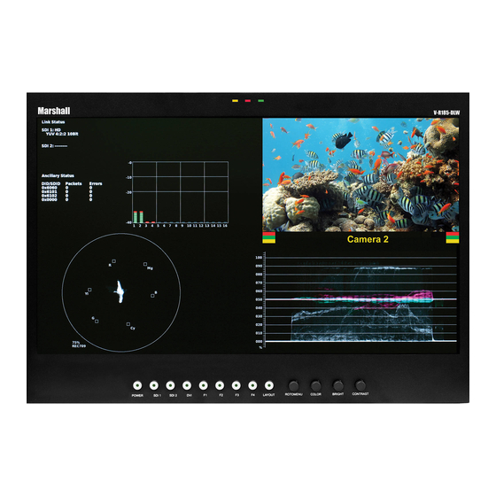
V-R185-DLW
Model No.
18.5" DLW Desktop and Rack Mount Dual Link / Waveform Monitor
Operating Instructions
Edition 1 Revision 7W
Marshall Electronics, Inc.
1910 East Maple Ave.
El Segundo, CA 90245
Tel: (800) 800-6608 / (310) 333-0606 • Fax: 310-333-0688
www.LCDRacks.com
•
sales@lcdracks.com
36
Advertisement
Table of Contents

Related Manuals for Marshall Electronics V-R185-DLW


Summary of Contents for Marshall Electronics V-R185-DLW
-
Page 1: Operating Instructions
Model No. 18.5” DLW Desktop and Rack Mount Dual Link / Waveform Monitor Operating Instructions Edition 1 Revision 7W Marshall Electronics, Inc. 1910 East Maple Ave. El Segundo, CA 90245 Tel: (800) 800-6608 / (310) 333-0606 • Fax: 310-333-0688 www.LCDRacks.com •... - Page 2 Warranty Marshall Electronics warranties to the first consumer that this V-R185-DLW LCD monitor will, under normal use, be free from defects in workmanship and materials, when received in its original container, for a period of one year from the purchase date.
-
Page 3: Table Of Contents
Table of Contents Installation and Initial Setup ------------------------------------------------------------------------------------------------------5 Top and Front Panel Features ----------------------------------------------------------------------------------------------------7 Rear Panel Features-----------------------------------------------------------------------------------------------------------------8 Compatible Input Formats---------------------------------------------------------------------------------------------------------9 MAIN MENU AND NAVIGATION------------------------------------------------------------------------------------------------ 10 Using the RotoMenu knob ------------------------------------------------------------------------------------------------------ 10 Marker Setup Submenu ..................................10 Video Config Submenu ..................................12 Color Config Submenu..................................16 System Config Submenu..................................16 OSD Config Submenu ..................................18 IMD Config Submenu ..................................21... -
Page 5: Installation And Initial Setup
■ The V-R185-DLW can be mounted in any standard EIA 19” equipment rack. The attached rack ears can be angled to provide the user control over the viewing angle. Adequate ventilation is required when installed to prevent possible damage to the monitor’s internal components. - Page 6 Dimensions...
-
Page 7: Top And Front Panel Features
Top and Front Panel Features Specifications PANEL Activation requires contact closure of pin to ground ■ on the HD-15 connector: Screen Size 18.5” Diagonal Display Area (h x v) 409.8 x 230.4 mm Pixels 1366 x RGB x 768 Viewing Angle (h x v) 178°... -
Page 8: Rear Panel Features
SDI Inputs / Outputs and DVI-I Input RS-422/RS-485 Serial Interface The V-R185-DLW has two 3G-SDI inputs and two active loop- The RS-422/485 ports are used to remotely control the IMD or through outputs. SDI 1 and SDI 2 can be used simultaneously all DLW features. -
Page 9: Compatible Input Formats
Timecode data packets, 0x6101 would count the EIA-708 CC data packets and 0x6102 would count the EIA-608 CC data The following video standards are supported by the V-R185-DLW: packets. Any ancillary packet ID can be chosen, from 0000 to FFFF. -
Page 10: Main Menu And Navigation
■ Limits Use the Limits option to differentiate data (indicated by a red highlight) on the Waveform display that goes above a Limit Max MAIN MENU AND NAVIGATION (maximum) and goes below a Limit Min (minimum) set in the Wave/Vector submenu. The Limit maximum and minimum can be set from 0000 to 1023. - Page 11 ■ Marker Enable Use this function to enable or disable screen markers. Using a function key or switching marker settings from the menu will automatically enable the markers. ■ 16:9 Markers Use this setting to superimpose one of 10 markers on the screen when in 16:9 or Full Screen mode. This setting is disabled when the aspect ratio is set to 4:3, or when Pixel-to-Pixel mode is enabled.
-
Page 12: Video Config Submenu
Use the Wave/Vector submenu to change the location of the Waveform Monitor and Vectorscope, as well as the data displayed on the Waveform monitor or the Vectorscope on the V-R185-DLW monitor. The Waveform Monitor can also be customized to conform to different scales, to display different colors, differentiate data with Limits. The Vectorscope targets can also be changed in this menu. - Page 13 Use this setting to enable monochrome mode. Only the luminance of the image will be displayed as a grayscale picture. The EIA-608 caption protocol defines four channels of caption information. The V-R185-DLW monitor can only display one of these four channels at any point in time. With the 608 Service selection, you can ■...
- Page 14 Video controlling device. T1, T2, T1T2, T2T1, T1-, T2-, T1T2-, T2T1-. Consult Image Video documentation for further information. As the V-R185-DLW monitor has a native resolution of 1366x768 RGB pixels, incoming images are automatically scaled to fit the screen: •...
- Page 15 ■ Analog Phase (DVI-Analog or VGA input only) The V-R185-DLW OSD tally can be controlled in a variety of different ways. Use the Tally Source setting to choose how tally is Adjusts the analog phase value to improve picture quality on DVI-A or VGA Sources. This adjusts the signal phase (not color controlled: phase) of the analog-to-digital conversion.
-
Page 16: Color Config Submenu
■ Overview The V-R185-DLW features an In-Monitor Display (IMD) with the ability to display on-screen text and tally in three colors. IMD text, color, and alignment can be assigned to each screen locally using menu options (see below). Alternately, IMD text and tally can be remotely controlled via the RS-422/485 serial interface using several industry-standard protocols, including TSL v4.0 and Image Video. - Page 17 ■ User-Definable Function Buttons When the Tally Source is set to TSL/MEI 422, OSD Tally can be set to Off or IMD: Use the Function 1, Function 2, Function 3 and Function 4 menu items to define each function button on the front panel of the monitor.
-
Page 18: Osd Config Submenu
• CC Monitor Display/hide Closed Caption Presence indicator Use this setting to enable or disable status display. When enabled, the current video input standard is displayed on the top • Audio Monitor Display/hide Audio Presence indicator left of the screen. When disabled, status is only displayed for 2 seconds when the monitor is powered on, when an input is •...
Need help?
Do you have a question about the V-R185-DLW and is the answer not in the manual?
Questions and answers