Table of Contents
Advertisement
Quick Links
Advertisement
Table of Contents

Related Manuals for Marshall Electronics V-LCD171MD


Summary of Contents for Marshall Electronics V-LCD171MD
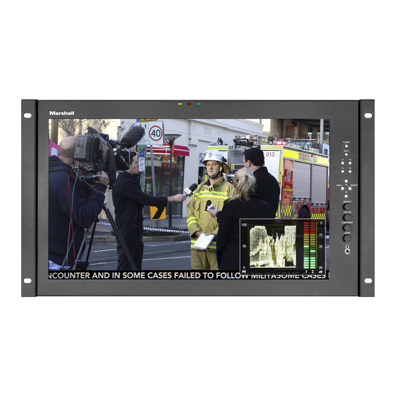
- Page 1 Marshall Electronics Model No. V-LCD171MD Operating Instructions...
- Page 2 This page intentionally leftblank...
-
Page 3: Table Of Contents
Table of Contents Installation and Initial Setup...............................4 Top and Front Panel Features ----------------------------------------------------------------------------------------------------5 Rear Panel Features-----------------------------------------------------------------------------------------------------------------6 Compatible Input Formats---------------------------------------------------------------------------------------------------------7 Main Menu and Navigation--------------------------------------------------------------------------------------------------------8 Using the menu buttons..................................8 Using the RotoMenu (BRIGHT) knob...............................8 Scaling Submenu .....................................9 Color Submenu....................................12 Markers Submenu ..................................14 Filters Submenu.....................................16 Audio Submenu .....................................20 Signal Analysis Submenu ................................21... -
Page 4: Installation And Initial Setup
Plug the power supply into an AC power source (100-240 V @ 50/60 Hz). Attach the Power connector to the back oft he monitor. Connectt he required cables for video signal input and output. (Power must be applied to the V-LCD171MD for the active loop- though outputt o be activated.) The monitor defaults to ‘ON’... -
Page 5: Top And Front Panel Features
Top and Front Panel Features Power Button once displays the current value. Pressing a knob twice resets the value to the default setting. Turn the display ON or OFF by pressing the power button. In the ON state, the LED on the power button will dim. In the User Control Knob OFF state, the LED on the button will be atf ull power. -
Page 6: Rear Panel Features
For activation oft he tally LEDs on the front oft he unit. HDMI Input and Output VESA mounting area The V-LCD171MD has one HDMI input and one active loop- through output. The HDMI Outputi s HDCP Compliant and will Standard VESA mount pattern for customized mounting NOT pass through HDCP protected content. -
Page 7: Compatible Input Formats
Compatible Input Formats MD-3GE 525i/60, 625i/50 720p/25, 29.97, 30, 50, 59.94, 60 1080p/23.98, 23.98sF, 24, 24sF, 25, 29.97, 30 1035i/59.94, 60 1080i/ 50, 59.94, 60 3G – Level A YCbCr, RGB 1080p/ 60, 59.94, 50 HDMI Input 480p59.94, 576p50 720p/25, 29.97, 30, 50, 59.94, 60 1080p/23.98, 23.98sF, 24, 24sF, 25, 29.97, 30 1080p/ 50, 59.94, 60 1035i/59.94, 60... -
Page 8: Main Menu And Navigation
Using the RotoMenu (BRIGHT) knob The Marshall Electronics RotoMenu concept has been broughtt o our line of camera top monitors to make navigating the Main Menu easier than ever. To RotoMenu functionality has been integrated into the BRIGHT knob, so that whenever the Main Menu is up, •... -
Page 9: Scaling Submenu
Scaling Submenu Use the Scaling submenu to adjust various scaling options and to allow greater control ofh ow your video signal is shown on the display. Scaling Submenu Input Crop • Enable the Input Crop function to selectt he area of active video that you would like shown on the image display. Selectt he desired Input by accessing the Adjust option below the main function: Adjust •... -
Page 10: Aspect Ratio
When you are satisfied with the position, press the SELECT button or press the BRIGHT knob to confirm your selection. The new cropped selection will be displayed on the screen. If your Aspect Ratio is sett o AUTO, the monitor will select the closest aspect ratio to the dimensions of your customized Input. - Page 11 Custom Aspect Ratio selection Pixel-to-Pixel Use this setting to enable Pixel-to-Pixel mode. This mode bypasses the monitor’s internal scaling function and displays images in their native resolution and aspect ratio, with a one-to-one mapping ofi ncoming image pixels to screen pixels: •...
-
Page 12: Color Submenu
Color Submenu IMD Configuration Submenu Temperature Use this setting to choose one oft hree color temperature presets: • D55 (5500K) • D65 (6500K) • D93 (9300K) • Custom (Adjustable Color Bias and Gain) • Linear (No processing is applied to the panel) Bias &... -
Page 13: Color Space
Use the buttons to select each individual bias or gain control. Highlighting the BIAS or GAIN icons enables a group change oft he Red, Green and Blue color components, respectively. Alternatively, you can use the BRIGHT knob to scroll through the different color components and settings. -
Page 14: Markers Submenu
Markers Submenu Use the Markers submenu to select various types of markers and settings in 4:3, 16:9, or Full Screen mode. Markers Submenu Marker Enable The Marker Enable setting turns 16:9 or 4:3 screen markers On or Off. By default, this setting is On. Center Marker Use this setting to display a center marker on the screen. - Page 15 • Off(No Marker) • 4:3 Aspect Ratio • 13:9 Aspect Ratio • 14:9 Aspect Ratio • 16:9 Aspect Ratio • 1.85:1 Aspect Ratio • 2.35:1 Aspect Ratio • 2.39:1 Aspect Ratio • 95% Safe Area • 93% Safe Area • 90% Safe Area •...
-
Page 16: Filters Submenu
Transparency (Opacity) Use this setting to selectt he transparency oft he marker background. Choose between 0% (black) , 25%, 50%, 75% and 100% (see through) transparency. Filters Submenu Use the Filters Submenu to enable various modes. Check Field Use the check field modes for monitor calibration or to analyze individual color components of an image. In Monochrome mode, all color is disabled and only a grayscale image is shown. -
Page 17: False Color
Enable Blue Check Field modeand adjustt he Color knob so thatt he outermost bars (white and blue) appear to match in brightness. Disable Blue Check Field mode. False Color This monitor has a false color filter to aid in the setting of camera exposure. As the camera Iris is adjusted, elements oft he image will change color based on the luminance or brightness values. - Page 18 Peaking (Focus assist) The Peaking Filter is used to aid the camera operator in obtaining the sharpest possible picture. You can turn the Peaking filter ON and adjustt he Threshold and Color by accessing the Adjustf unction. Use the BRIGHT knob to adjustt he Threshold.
- Page 19 In the image above, the Lower Threshold has been sett o 20 IRE (Red). This means that any part oft he image UNDER 20 IRE will be “colored” in RED. Also, the Upper Threshold has been sett o 90 IRE (Yellow). This means that any part oft he image OVER 90 IRE will be “colored”...
-
Page 20: Audio Submenu
Audio Submenu Use the Audio Submenu to enable and adjustt he various Audio functions available. Volume Use this function adjustt he volume oft he Headphone jack audio signal. Mute Use this function to Mute (ON) or Unmute (OFF) the audio outputf rom the Headphone jack. Channels Use this function to select which stereo audio pair to route to the headphone jack. -
Page 21: Signal Analysis Submenu
Signal Analysis Submenu Use the Video Configuration submenu to select various video settings such as monochrome mode or blue-only mode. Signal Analysis Submenu Enable Use this setting to enable the signal analysis instruments selected in the Layout mode. Layout Select which oft he signal analysis instruments to display on screen. You can display an Audio Meter (Audio) or a Waveform monitor (VIDEO) or both simultaneously. -
Page 22: User Settings Submenu
User Settings Submenu Use the User Settings submenu to customize User Settings and Function buttons on the monitor’s keypad for easy access to frequently used features. Save State Use this setting to save the state oft he monitor to 1 of 6 available slots. Load State Use this setting to load a previously configured monitor state. -
Page 23: System Submenu
• Marker Width Toggle through On-Screen Marker widths • Marker Color Toggle through On-Screen Marker colors • Marker Transparency Toggle through Marker Background Transparency settings • Check Field Toggle through Check Field options • False Color Enable/disable False Color filter •... -
Page 24: Input Format Osd
*Raising the backlight value will increase the amount of current used by the monitor, which will reduce battery time. Splash Screen Use this setting to save the enable (ON) or disable (OFF) the “Marshall Electronics, Inc.” splash screen on monitor power up. Curtain Color Use this setting to select between different Curtain Color settings for the monitor. -
Page 25: Specifications
Specifications PANEL Screen Size 17.3” Diagonal Display Area (h x v) 381.89 x 214.81 mm Pixels 1920 x RGB x 1080 Brightness 400 cd/m2 Contrast Ratio 600:1 VIDEO INPUT/OUTPUT HDMI Input / Output CONNECTORS HDMI Video Input 1 x HDMI Female Receptacle HDMI Video Output (Active Loop-Through) 1 x HDMI Female Receptacle Stereo Headphone Jack... -
Page 26: Dimensions
Dimensions... -
Page 27: Maintenance
Warranty Marshall Electronics warranties to the first consumer thatt his V-LCD171MD LCD monitor will, under normal use, be free from defects in workmanship and materials, when received in its original container, for a period of one year from the purchase date. - Page 28 Marshall Electronics Tel: (800) 800-6608 / (310) 333-0606 • Fax: 310-333-0688 www.LCDRacks.com • sales@lcdracks.com...
Need help?
Do you have a question about the V-LCD171MD and is the answer not in the manual?
Questions and answers