Table of Contents
Advertisement
Quick Links
Advertisement
Table of Contents

Related Manuals for Marshall Electronics V-LCD101MD


Summary of Contents for Marshall Electronics V-LCD101MD
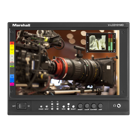
- Page 1 Marshall Electronics V-LCD101MD Model No. 10.1” Camera-Top Monitor with Modular Input/Output Operating Instructions ICW 11-30-2016 Marshall Electronics, Inc. 20608 Madrona Ave Torrance, CA 90503 Tel: (800) 800-6608 / (310) 333-0606 • Fax: 310-333-0688 www.LCDRacks.com • sales@lcdracks.com...
- Page 2 Warranty Marshall Electronics warranties to the first consumer that this V-LCD101MD LCD monitor will, under normal use, be free from defects in workmanship and materials, when received in its original container, for a period of one year from the purchase date.
-
Page 3: Table Of Contents
Table of Contents Installation and Initial Setup____________________________________________________ 5 Top and Front Panel Features__________________________________________________ 6 Rear Panel Features_________________________________________________________ 7 Compatible Input Formats_____________________________________________________ 8 Main Menu and Navigation____________________________________________________ 9 Using the menu buttons_______________________________________________________ 9 Using the RotoMenu (BRIGHT) knob_____________________________________________9 Scaling Submenu___________________________________________________________ 10 Color Submenu____________________________________________________________ 13 Markers Submenu__________________________________________________________ 15 Filters Submenu____________________________________________________________ 17... - Page 4 Dimensions This page intentionally left blank...
-
Page 5: Installation And Initial Setup
Plug the power supply into an AC power source (100-240 V @ 50/60 Hz). Attach the Power connector to the back of the monitor. Connect the required cables for video signal input and output. (Power must be applied to the V-LCD101MD for the active loop- HDMI Video Output (Active Loop-Through) though output to be activated.) The monitor defaults to ‘ON’... -
Page 6: Top And Front Panel Features
Top and Front Panel Features Menu Time-Out ■ Use this setting to set the Menu Time-Out length. Select between 10-30 seconds (5 second increments) or Off to disable automatic Menu Time-Out. Version ■ Use this function to view the current Firmware versions of all monitor components. Power Button adjustment parameter is shown on the bottom left of the screen, with values ranging from 0 to 100. -
Page 7: Rear Panel Features
■ For upgrade / debugging purposes ONLY. Please contact Use this setting to save the enable (ON) or disable (OFF) the “Marshall Electronics, Inc.” splash screen on monitor power up. Marshall Electronics before attempting to use this port. Curtain Color ■... -
Page 8: Compatible Input Formats
Compatible Input Formats • Marker Width Toggle through On-Screen Marker widths • Marker Color Toggle through On-Screen Marker colors • Marker Transparency Toggle through Marker Background Transparency settings MD-3GE • Check Field Toggle through Check Field options • False Color Enable/disable False Color filter 525i/60, 625i/50 •... -
Page 9: Main Menu And Navigation
Using the RotoMenu (BRIGHT) knob ■ The Marshall Electronics RotoMenu concept has been brought to our line of camera top monitors to make navigating the Main Use this setting to select the functions to be activated by the F1-F4 buttons on the monitor’s keypad. -
Page 10: Scaling Submenu
Signal Analysis Submenu Scaling Submenu Use the Video Configuration submenu to select various video settings such as monochrome mode or blue-only mode. Use the Scaling submenu to adjust various scaling options and to allow greater control of how your video signal is shown on the display. - Page 11 When you are satisfied with the position, press the SELECT button or press the BRIGHT knob to confirm your selection. Audio Submenu Use the Audio Submenu to enable and adjust the various Audio functions available. The new cropped selection will be displayed on the screen. If your Aspect Ratio is set to AUTO, the monitor will select the closest aspect ratio to the dimensions of your customized Input.
- Page 12 In the image above, the Lower Threshold has been set to 20 IRE (Red). This means that any part of the image UNDER 20 IRE will be “colored” in RED. Also, the Upper Threshold has been set to 90 IRE (Yellow). This means that any part of the image OVER 90 IRE will be “colored”...
-
Page 13: Color Submenu
The outer square represents the entire image and the inner grey box represents your current Pixel to Pixel selection. Peaking (Focus assist) ■ Use the COLOR knob to move your selection LEFT and RIGHT. Use the CONTRAST knob to move your selection UP or DOWN. Press the SELECT button or the ROTOMENU knob to lock in your selection. - Page 14 False Color ■ When selecting the RGB Bias and Gain submenu, bias adjustment indicators will appear at the top of the screen, and gain adjustment indicators will appear at the bottom of the screen: This monitor has a false color filter to aid in the setting of camera exposure. As the camera Iris is adjusted, elements of the image will change color based on the luminance or brightness values.
-
Page 15: Markers Submenu
Color Space ■ Adjust the Contrast knob until an even grayscale appears along the top bars. Use this setting to automatically detect (Auto) or select the color space (RGB or YCrCb) of incoming HDMI video. This should Disable Monochrome mode. match the color space of the video output settings on your playback device. -
Page 16: Filters Submenu
Line Color ■ Marker Selection ■ Use this setting to select a custom color for the Screen Markers. You can choose between White (default), Yellow, Red, Use this setting to adjust and view the settings of 1 of 2 available markers. Green and Blue.
Need help?
Do you have a question about the V-LCD101MD and is the answer not in the manual?
Questions and answers