Table of Contents
Advertisement
Quick Links
Advertisement
Table of Contents

Subscribe to Our Youtube Channel
Related Manuals for Marshall Electronics V-MD151


Summary of Contents for Marshall Electronics V-MD151
-
Page 1: Operating Instructions
V-MD151 Model No. Rack Mountable High Definition LCD Monitor Operating Instructions Marshall Electronics, Inc. 1910 East Maple Ave. El Segundo, CA 90245 Tel: (800) 800-6608 / (310) 333-0606 • Fax: 310-333-0688 www.LCDRacks.com • sales@lcdracks.com... - Page 2 Warranty Marshall Electronics warranties to the first consumer that this V-MD151 LCD monitor will, under normal use, be free from defects in workmanship and materials, when received in its original container, for a period of one year from the purchase date.
- Page 3 Page Intentionally Left Blank Page Intentionally Left Blank...
-
Page 4: Table Of Contents
Table of Contents Installation and Initial Setup ------------------------------------------------------------------------------------------------------5 Top and Front Panel Features ----------------------------------------------------------------------------------------------------6 Rear Panel Features-----------------------------------------------------------------------------------------------------------------7 Compatible Input Formats---------------------------------------------------------------------------------------------------------8 Input Module Installation----------------------------------------------------------------------------------------------------------9 MAIN MENU AND NAVIGATION------------------------------------------------------------------------------------------------ 11 VIDEO CONFIGURATION SUBMENU...............................11 MARKER CONFIGURATION SUBMENU ............................14 FILTER CONFIGURATION SUBMENU...............................17 SYSTEM CONFIGURATION SUBMENU ............................19 FUNCTION PRESETS SUBMENU ..............................20 IMD &... -
Page 5: Installation And Initial Setup
■ The V-MD151 can be mounted in any standard EIA 19” equipment rack. The attached rack ears can be angled to provide the user control over the viewing angle. Adequate ventilation is required when installed to prevent possible damage to the monitor’s internal components. -
Page 6: Top And Front Panel Features
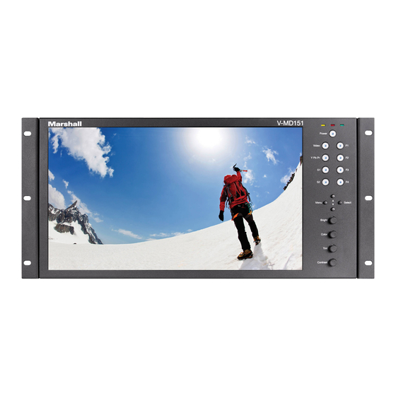
Top and Front Panel Features Specifications PANEL ■ CN-1 – Programming Port* Factory / Upgrade Use Only Screen Size 15.6” Diagonal Display Area (h x v) 344.16 x 193.59 mm Pixels 1920 x RGB x 1080 TALLY Hardware Interface (HD-15) ■... -
Page 7: Rear Panel Features
This shows the Keypad firmware version of your monitor. fits inside the VESA Screw Length WARNING silkscreen) with The V-MD151 has CVBS and YPbPr inputs and one active loop- ■ Slot (1 or 2) the 75mm hole pattern in order to avoid obstructing Module through output for each input. -
Page 8: Compatible Input Formats
Compatible Input Formats The following video standards are supported by the V-MD151: Video Input NTSC, PAL YPbPr Input 480i, 576i/50 480p, 576p/50 720p/25, 29.97, 30, 50, 59.94, 60 1080p/23.98, 23.98sF, 24, 24sF 1080i/50, 59.94, 60 Optional Input Modules (Type A modules) MD-3GSDI and MD-TC –... -
Page 9: Input Module Installation
Use this feature to choose between controlling the Contrast of the image or the intensity of the panel’s Backlight with the Input Module Installation CONTRAST button on your monitor. Note: While the Contrast control moves up and down at intervals of 1, the Backlight control will move up and down at intervals of 2, from 0-100. - Page 10 ■ Splash Screen Use this option to enable or disable the Marshall Electronics Inc. splash screen seen when the monitor is first powered on. ■ Freeze Use the Freeze function to “freeze” the current image on the screen. Select this menu item again (Unfreeze) to return to the real-time video input.
-
Page 11: Main Menu And Navigation
MAIN MENU AND NAVIGATION Access the main menu by pushing and holding the MENU button on the front panel of the monitor. •Step through menu items using the ▲ and ▼ buttons. •Choose a submenu or select a menu item by pressing SELECT. •Return to the previous menu by pressing MENU. - Page 12 Use this setting to choose one of three color temperature presets: FILTER CONFIGURATION SUBMENU • D55 (5500K) • D65 (6500K) • 9300K • USER (Adjustable Color Bias and Gain) • Linear (No processing is applied to the panel) Use this setting to enable monochrome mode. Only the luminance of the image will be displayed as a grayscale picture. ■...
- Page 13 • 85% Safe Area • 80% Safe Area Use the following procedure when calibrating the monitor to SMPTE color bars with the following procedure: 4:3 Marker Examples: Allow the monitor to warm up for at least 5-10 minutes. Display SMPTE split-field color bars on the monitor using an external source. Enable Monochrome mode.
-
Page 14: Marker Configuration Submenu
Use this setting to enable or disable all on-screen markers. This setting affects the center marker, full screen markers, 16:9 markers and 4:3 markers. ■ Center Marker Use this setting to display a center marker on the screen. ■ 16:9 Markers Use these settings to superimpose one of 12 markers on the screen when in 16:9 mode.
Need help?
Do you have a question about the V-MD151 and is the answer not in the manual?
Questions and answers