Table of Contents
Advertisement
Quick Links
Next
Generation
If you need assistance with parts or have assembly questions, please call Customer Service at
Please read the entire instruction manual carefully before proceeding with the assembly or use of your
new gym set. SAVE THIS MANUAL for future reference in the event that you need to contact us for
LEISURE TIME PRODUCTS
866-362-1123
Our regular office hours are
Monday through Friday, 7:00 a.m. to 4:00 p.m. Central Time
assistance or replacement part information and ordering.
MODEL #5007
ASSEMBLY MANUAL
YOUR WARRANTY
Playground, Inc., dba Leisure Time
Products, provides a 1-year limited
Warranty. See inside back cover of this
manual for details.
We take great care to design our products
with your child's safety in mind. However,
only with careful supervision and proper
safety instructions, can you be assured of
safe play time on any product designed for
children.
Assembly requires
at least two adults.
For Residential Only
Advertisement
Table of Contents

Summary of Contents for Leisure Time 5007
- Page 1 Next MODEL #5007 ASSEMBLY MANUAL Generation YOUR WARRANTY Playground, Inc., dba Leisure Time Products, provides a 1-year limited warranty. See inside back cover of this manual for details. We take great care to design our products with your child's safety in mind. However,...
- Page 2 We recommend that you apply a wood ends. sealant or protectant at the time of SEE PAGES 34 THRU 36 FOR MAINTENANCE TIPS Page 1 - SAFETY & ASSEMBLY INFO Next Generation 5007 061206 © Copyright Playground Inc...
- Page 3 At this time and always, review the "safety and general information - cautions for use" sections with each child using the play product. Page 2 - SAFETY & ASSEMBLY INFO Next Generation 5007 061206 © Copyright Playground Inc...
- Page 4 22125 Rock Creek Rd. Sheridan, OR 97378 Preservative: Pacbor Treated (Disodium Octaborate Tetrahydrate) Retention level: .118 pcf Wood species: Pine, White Fir, Hem Fir, and/or Doug Fir Page 3 - SAFETY & ASSEMBLY INFO Next Generation 5007 061206 © Copyright Playground Inc...
- Page 5 A FALL ON TO A HARD SURFACE COULD RESULT IN SERIOUS INJURY Any edging used to contain the ground must be beyond the safe play area. (Ex. Landscape timbers or railroad ties) Page 4 - SAFETY & ASSEMBLY Next Generation 5007 061206 © Copyright Playground Inc...
- Page 6 Page 5 - SAFETY & ASSEMBLY Next Generation 5007 061206 © Copyright Playground Inc...
- Page 7 DO NOT over tighten DO NOT over tighten there are no protruding sharp edges. AND CAUSE AND CAUSE wood and then use a ½" SPLINTERING SPLINTERING socket to tighten. Page 6 - USING THE HARDWARE © Copyright Playground Inc Next Generation 5007 061206...
- Page 8 Page 7 - PART LOCATOR Next Generation 5007 061206 © Copyright Playground Inc...
- Page 9 1 x 3-1/2 x 45 [ 2.54 x 8.89 x 114.30 ] 1 x 3-1/2 x 45 [ 2.54 x 8.89 x 114.30 ] Page 8 - WOODEN PARTS C1 - H9 Next Generation 5007 061206 © Copyright Playground Inc...
- Page 10 11/16 x 2-1/2 x 16 [ 1.74 x 6.35 x 40.64 ] 11/16 x 2-1/2 x 29 [ 1.74 x 6.35 x 73.66 ] Page 9 - WOODEN PARTS H10 - N3 Next Generation 5007 061206 © Copyright Playground Inc...
- Page 11 Page 11 and take special care to note the sizes given in each step. See page 6 for proper installation instructions. Page 10 - HEX HEAD BOLTS SCREWS & WASHERS Next Generation 5007 061206 © Copyright Playground Inc...
- Page 12 1 - METAL ID PLAQUE 4 - GROUND STAKES 1 - ASSEMBLY MANUAL 1 - POUNDING BLOCK 4 - Y28 15 1/4" METAL DOWELS Page 11 - FASTENER DETAIL LIST & MISC. PARTS Next Generation 5007 061206 © Copyright Playground Inc...
- Page 13 Tooth Lock Washers , Flat Washers and Spike attach H3, again noting single hole toward C2 Post, T Nut. using 5/16 x 3-3/4” Hex Bolt, Internal Tooth Lock Washers and Flat Washers Page 12 Next Generation 5007 061206 © Copyright Playground Inc...
- Page 14 5/16 X 3-3/4" HEAD BOLT STEP 6 Attach Right Floor Rail H7 to C3 Post using 5/16 x 3-3/4” Hex Bolts, Internal Tooth Lock Washers, Flat Washers and Spike T Nut. Page 13 Next Generation 5007 061206 © Copyright Playground Inc...
- Page 15 5/16 X 3-3/4" HEAD BOLT STEP 8 Attach H8 Floor Rail, four-hole, to C1 Post using 5/16 x 3-3/4” Hex Bolts, Internal Tooth Lock Washers, Flat Washers and Spike T Nut. Page 14 Next Generation 5007 061206 © Copyright Playground Inc...
- Page 16 Attach G5 Left Baseboard to C2 Post, flushing with outside of G1 Baseboards, pilot drill with 3/16"bit using holes in G5 as guide and attach using 5/16x2-1/2” Lag Screws, Internal Tooth Lock Washers and Flat Washers. Page 15 Next Generation 5007 061206 © Copyright Playground Inc...
- Page 17 Left side of C1 Post, pilot drill with 3/16" bit using holes in G7 as a guide. Attach using 2-1/2” Lag Screws, Internal Tooth Lock Washers and Flat Washers. Page 16 Next Generation 5007 061206 © Copyright Playground Inc...
- Page 18 " WOOD SCREW STEP 14 Attach H4 Top Floor Joist between H6 Left Floor Rail and H7 Right Floor Rail using four 2-1/2” Wood Screws. Note: Center screws into H7. Page 17 Next Generation 5007 061206 © Copyright Playground Inc...
- Page 19 Tower Posts, pilot drill using 3/16" bit and attach using 2-1/2” Lag Screws, Internal Tooth Lock Washers and Flat Washers. STEP 17 At this point, place the Y18 Plastic Post Caps on all six of the Tower Posts. Page 18 Next Generation 5007 061206 © Copyright Playground Inc...
- Page 20 Right Floor Rail. Attach using 2” Wood Screws. STEP 20 On Upper Floor place M3, five-hole Floor Boards, seven on each side of N1 Center Floor Board, and space evenly. Then attach using 2” Wood Screws. Page 19 Next Generation 5007 061206 © Copyright Playground Inc...
- Page 21 Drive 5/16” Spike T-Nuts into inside of C2 and C1 Posts. Then attach G2 Sculptured Rails to front and back of C2 and C1 Posts using 5/16 x 3-3/4” Hex Bolts, Internal Tooth Lock Washers and Flat Washers. Page 20 Next Generation 5007 061206 © Copyright Playground Inc...
- Page 22 Boards on Top-Lower Floor spacing evenly using 2” Wood Screws. STEP 25 At this point, install Lower Deck Floor Boards, M3, using 2” Wood Screws spacing fifteen M3 Floor Boards evenly. Page 21 Next Generation 5007 061206 © Copyright Playground Inc...
- Page 23 Attach M5, four-hole, Clubhouse Rail at C1 Post above Lower and Top Deck; measuring 2-1/4” up from top of M3 Floor Board mark C1 Post. Attach using 2” Wood Screws. Page 22 © Copyright Playground Inc Next Generation 5007 061206...
- Page 24 Floor Board. At this point, keep G8 as plumb up and down as possible and attach to G2 Sculptured Top Rail using 1-1/2” Wood Screws. Now in the pre-drilled holes on M8 Wall Rails attach to C-Posts with 2-1/2” Wood Screws. Repeat G8 and M8 process on back of tower. Page 23 Next Generation 5007 061206 © Copyright Playground Inc...
- Page 25 3/16" bit and fasten with 2-1/2” Lag Screws, Internal Tooth Lock Washers and Flat Washers. STEP 32 Attach H1 Roof Supports flush with outside of H5s, Front and Back of Tower Structure and fasten with 2” Wood Screws. Page 24 Next Generation 5007 061206 © Copyright Playground Inc...
- Page 26 Attach M2 Roof Spacers at front and back to G2 Sculptured Rails flushing with inside of G2 Sculptured Rails. Use 2” Wood Screws through pre-drilled holes in M2s to fasten. Page 25 Next Generation 5007 061206 © Copyright Playground Inc...
- Page 27 Top of G2 and flush with end of M7 Window Trim and fasten with 1-1/2” Wood Screws; finish by fastening top of Wall Boards N3 and M10s to M7, using 1/1/4” Wood Screws. Page 26 Next Generation 5007 061206 © Copyright Playground Inc...
- Page 28 Internal Tooth Lock Washers and Flat Washers. Make sure that H9 is flush with outside of C3. Now attach six M9 Wall Boards to H9 Wall Rails on right side of Tower spacing approximately 2-3/4” apart using 1-1/2” Wood Screws. Page 27 Next Generation 5007 061206 © Copyright Playground Inc...
- Page 29 Wood Screws. Now measure up 24” from G1 Baseboard and mark Post 24" again. Place bottom of M1 Rail with mark and attach to C2 and C1 Posts using 2” Wood Screws. Page 28 © Copyright Playground Inc Next Generation 5007 061206...
- Page 30 #8 X 1-1/4 " WOOD #8 X 2 " SCREW WOOD SCREW STEP 45 Attach six M9 Wall Boards to inside of M4 Wall Rails approximately 2-3/4” apart using 1-1/4” Wood Screws. Page 29 Next Generation 5007 061206 © Copyright Playground Inc...
- Page 31 Entry Ladder Rails are 16” apart outside to outside. Then attach M11 Entry Ladder Back to inside of Ladder Rails measuring up from bottom 1/8” and fastening with 2” Wood Screws. 16" Page 30 Next Generation 5007 061206 © Copyright Playground Inc...
- Page 32 Now use hole in bottom of handle as guide to pilot drill and finish attaching with 2 ½” lag screw, lock washer and flat washer. Page 31 © Copyright Playground Inc Next Generation 5007 061206...
- Page 33 STEP 51 Install Window Mesh at top and bottom inside of Window using 3/4” Washer Head Screws. Inside Tower STEP 94 #8 X 3/4 WASHER HEAD SCREW " Page 32 Next Generation 5007 061206 © Copyright Playground Inc...
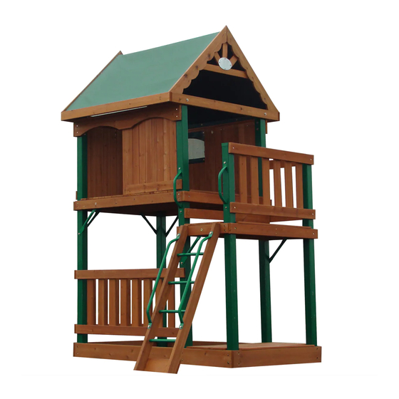
- Page 34 WASHER Washer Head Screws. HEAD SCREW Your Lowe's 5007 Next Generation Tower is now finished. Here is a layout for Accessories that you may add to your Tower which can be purchased at your Lowe's Stores. Page 33 Next Generation 5007 061206...
- Page 35 Please dispose of the unit in such a way that no unreasonable hazards will exist (sharp edges, broken parts, and exposed screws) at the time it is discarded. Page 34 - MAINTENANCE Next Generation 5007 061206 © Copyright Playground Inc...
- Page 36 However, if rocks or roots surface under the base support pieces, these protrusions must be removed or the play product relocated to another area in order to eliminate rocking. Page 35 - MAINTENANCE Next Generation 5007 061206 © Copyright Playground Inc...
- Page 37 Question: Who can I hire to assemble my playset? Answer: We do not suggest assemblers. Please refer to your yellow pages or ask for a recommendation from where you purchased your playset. Page 36 - MAINTENANCE Next Generation 5007 061206 © Copyright Playground Inc...
- Page 38 : 1-YEAR LIMITED WARRANTY It is the customers' responsibility to install and maintain their playset as instructed in the instruction manual. Subject to normal use, Leisure Time Products, Inc. warrants to the original purchaser all products to be free from workmanship defects for a period of one-year from the date of the original purchase.
- Page 39 MODEL #5007 ASSEMBLY MANUAL LEISURE TIME PRODUCTS Next Generation DETACH HERE AND MAIL WARRANTY REGISTRATION CARD LEISURE TIME PRODUCTS, INC. P.O. Box 459 Siloam Springs, AR 72761 1-866-362-1123 Toll Free Office hours: 7am - 4pm, Mon-Fri, Central Time...
-
Page 40: Assembly Instructions
© Copyright Playground Inc © Copyright Playground Inc If you need assistance with parts or have assembly questions, please call Customer Service at 866-362-1123. Our regular office hours are LEISURE TIME PRODUCTS Monday through Friday, 7:00 a.m. to 4:00 p.m. Central Time... - Page 41 ( E1 ) Long Angle Brace * 1 Hole * 30° - 60° * 1-1/2 x 3-1/2 x 85 ( B1 ) Beam End Post * 3 Holes * 3-1/4 x 3-1/4 x 47 METAL TRIANGLE STEP 2 5/16 X 4" Attach the two Metal Triangles HEAD Y1 to the Swing Beam as shown...
- Page 42 (G1 ) Beam Ground Board * 4 Holes * 1 x 5-1/2 x 89 ( E2 ) Beam End Support * 4 Hole * 1-1/2 x 3-1/2 x 40-3/4 STEP 5 Pilot drill with 3/16" bit using holes in G1 as guide and attach the G1 Beam Ground Board to the assembly using four 2"...
- Page 43 STEP 7 Attach the support assembly to the Swing Beam with the Metal Triangles Y1 using two 4” Hex Head Bolts, Lock Washers, Flat Washers and Lock Nut. 5/16 X 4" HEX HEAD BOLT 5/16" X 2018 NYLOCK LOCK NUT 5/16"...
- Page 44 5/16” x 2” HEX HEAD BOLT STEP 9 Using the pre-drilled holes in the G4 Club House Wall Rail as a guide, drill thru the Wall Boards using a 3/8” drill bit. Install four 5/16” Spiked T Nuts, from the inside of the Tower, into these holes. Turn over the Swing Beam Assembly, stand it up, and line up the holes in the Y16 Swing Beam Mount to the holes in the G4 Club House Wall Rail.
- Page 45 © Copyright Playground Inc Si necesita ayuda con las partes o tiene preguntas sobre el ensamblaje, por favor PRODUCTOS LEISURE TIME llame al Dpto. de Servicio al Cliente al 866-362-1123. Nuestras horas regulares de oficina son de lunes a viernes, de 7:00 a.m. a 4:00 p.m. Hora Central.
- Page 46 ( E1 ) Refuerzo largo en ángulo * 1 agujero * 30° - 60° * 1-1/2 x 3-1/2 x 85 ( B1 ) Poste para extremo de barra * 3 agujeros * 3-1/4 x 3-1/4 x 47 TRIÁNGULO DE METAL PASO 2 PERNO CABEZA HEXAGONAL DE...
- Page 47 (G1 ) Tabla de apoyo A tierra * 4 agujeros * 1 x 5-1/2 x 89 ( E2 ) Soporte de extremo para la barra * 4 agujeros * 1-1/2 x 3-1/2 x 40-3/4 PASO 5 Haga un agujero piloto con la broca de 3/16 in.
- Page 48 PASO 7 Fije el ensamble del soporte a la barra para columpio con los triángulos de metal Y1 utilizando dos pernos cabeza hexagonal de 4 in. (10 cm), arandelas de seguridad, arandelas planas y tuerca de seguridad. TUERCA P E R N O C A B E Z A H E X A G O N A L D E 5 / 1 6 x 4 in. MECÁNICA DE (8 mm x 10 cm) SEGURIDAD DE...
- Page 49 PERNO CABEZA HEXAGONAL DE 2 in. (5 cm), ARANDELA DE SEGURIDAD DE 5/16 in. (8 mm) TUERCA EN T DE 5/16 in. (8 mm) CON ESPIGA ARANDELA PLANA DE PASO 9 5/16 in. (8 mm) Utilizando los agujeros pre-taladrados en el larguero para pared de la casa club G4 como guía, taladre a través de las tablas de pared utilizando una broca de 3/8 in.
Need help?
Do you have a question about the 5007 and is the answer not in the manual?
Questions and answers