NEC XN120 Getting Started Manual
System telephones
Hide thumbs
Also See for XN120:
- Feature manual (222 pages) ,
- Getting started manual (83 pages) ,
- User manual (40 pages)
Table of Contents
Advertisement
Quick Links
This guide explains the installation, configuration and operation of the XN120 Telephone System
including the exchange line and telephone connections.
Further information will be supplied with any optional equipment that you have purchased.
Please keep all information supplied for future reference.
Regulatory Notice.
Refer to the Declaration of Conformity related to the product at the end of this document.
Warning: This is a class A product. In a domestic environment this product may cause radio
interference in which case the user may be required to take adequate measures.
XN120
Getting Started Guide
Rev 1.2 (March 2005)
991409-5
Advertisement
Table of Contents

Related Manuals for NEC XN120


Summary of Contents for NEC XN120
- Page 1 This guide explains the installation, configuration and operation of the XN120 Telephone System including the exchange line and telephone connections. Further information will be supplied with any optional equipment that you have purchased. Please keep all information supplied for future reference.
-
Page 2: Table Of Contents
Connecting the 64 Button Consoles.........................14 5- Connect the Exchange Lines ........................16 6- Connecting the External Music on Hold Device..................17 7- Connecting the XN120 to an External Paging System................18 8- Connect the Power & System Start Up ......................19 9- Test the System ..............................21 10- Configure the XN120 ............................23... -
Page 3: What Is The Xn120
Separate guides are supplied with the optional equipment. All equipment will operate when the XN120 is installed as shown in this guide; it is not necessary to make any changes to the system configuration. -
Page 4: Xn120 System Telephones
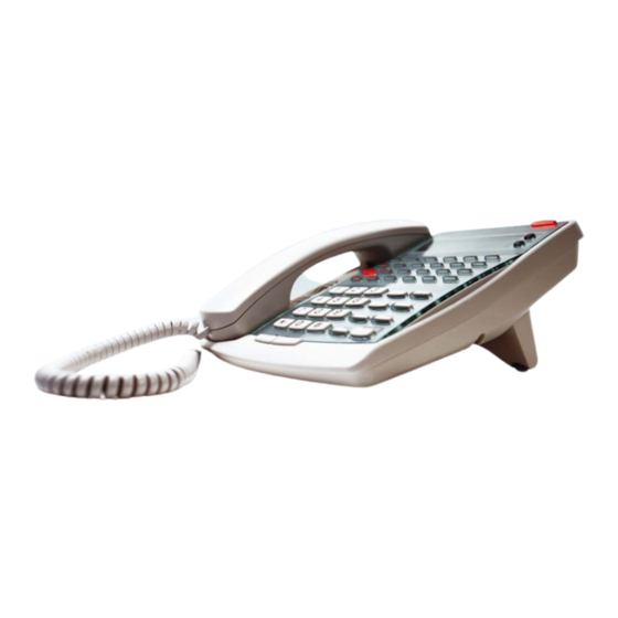
Built in Built in You can connect up to 8 XN120 system telephones to any of the station connections. (If you need more telephones you will need to install optional cards). The XN120 system telephones have feature keys and illuminated function keys that can be tailored to your own requirements. -
Page 5: System Connection Diagram
2 Relay contacts available that can be assigned to Each expansion cabinet requires a dedicated power any of the door units or audio ports. cable. Connected to the EXIFU card in the Main XN120 unit via an RJ45 cable. DSPDB Voice Mail and Voice response unit. -
Page 6: Installation Procedure
See page 7 for details. If so, it is recommended that you do not disconnect all of the exchange Are you replacing an lines or telephones until you are certain that the XN120 is installed and existing telephone system ? operating correctly. -
Page 7: 1- Unpack The System
Recommended cable type: Twisted pair (CW1308 or similar specification) · Conductor diameter: 0.4 to 0.6 mm Other Documentation Available All documents are available on the XN120 Technical CD 991425-5 XN120 PC Pro Getting Started Guide 991421-5 XN120 Basic Rate ISDN Guide... -
Page 8: 2- Replacing An Existing Telephone System
Replacing an Existing Telephone System 2- Replacing an Existing Telephone System If you are replacing your existing telephone system with the XN120 we recommend that you check the following. · Do not disconnect all of the lines or extensions from your existing telephone system. If for any reason you have problems installing the XN120 you will need your old system in working order to continue your business. -
Page 9: 3- Wall Mount The Xn120 System
Wall Mount the XN120 System 3- Wall Mount the XN120 system Installation Considerations: · To avoid electric shock or damage do not plug in or turn on the system power before completing the installation. · Avoid working with the system during electrical storms. - Page 10 Wall Mount the XN120 system Push Remove the sub cover of the XN120. Slide Hook Hook the XN120 onto the wall onto mount screws. screws Tighten the lower screws to secure the unit to the wall. Fasten lower two screws Earth the XN120 system.
-
Page 11: 4- Connect The Telephones
Aerial distribution wiring is not allowed. Connecting the XN120 System Phones The XN120 system phones can be connected to any of the eight RJ11 telephone sockets labelled ST1 to ST8 in the XN120 unit. The XN120 is supplied with RJ11 to bare wire cables for connection to optional distribution frames. - Page 12 Remove the breakouts of the sub cover before re-fitting onto the system. Use the telephone cables Refer to the diagram above for the pin numbering of the XN120 RJ11 supplied with the XN120 and sockets (ST1 to ST8). RJ45 sockets.
-
Page 13: Connecting The Normal Phones
The normal phones can be connected to any of the eight RJ11 telephone sockets labelled ST1 to ST8 on the XN120. The XN120 is supplied with RJ11 to bared wire cables for connection to optional distribution frames. ! Check Power Fail Operation later in this guide, ST8 can be used to provide a working telephone should the power be disconnected from the XN120. -
Page 14: Connecting The 64 Button Consoles
! Check Power Fail Operation later in this guide, ST8 can be used to provide a working telephone should the power be disconnected from the XN120. You cannot use socket ST8 for both power fail and a 64 Button DSS console;... - Page 15 Connect the Telephones Use the telephone cables Refer to the diagram above for the pin numbering of the XN120 RJ11 supplied with the XN120 and socket (ST8). RJ45 sockets. Connections: XN120 RJ45 socket ST socket Pin 2 black White/green Pin 5 yellow...
-
Page 16: 5- Connect The Exchange Lines
· Use lightning protectors for each exchange line. Use the cables supplied with The exchange line cables supplied with the XN120 can be used to the XN120. connect to the lines supplied by your Network Provider. ! Ensure each line has a lightning protection device included. -
Page 17: 6- Connecting The External Music On Hold Device
The external music device is connected to the RJ11 socket labelled MOH/PAGE located under the sub cover to the right of the ST1-ST8 sockets. An RJ11 cable is supplied with the system. The external music device is not supplied with the XN120. The connections of the RJ11 plug supplied with the XN120: XN120... -
Page 18: 7- Connecting The Xn120 To An External Paging System
The external paging system is connected to the RJ11 socket labelled MOH/PAGE located under the sub cover to the right of the ST1-ST8 sockets. An RJ11 cable is supplied with the system. The external paging system is not supplied with the XN120. The connections of the RJ11 plug supplied with the XN120: XN120... -
Page 19: 8- Connect The Power & System Start Up
Ensure the power is switched off at the source. System Start Up – First Time ! The first time you start up the XN120 it is important to clear the system memory. This will ensure that the system is set to the default configuration. - Page 20 Switching the XN120 OFF ! Be sure that no calls are in progress otherwise they will be cut off. Turn the power switch off on the left side of the XN120 unit. System Start Up – Retain Customer Configuration This is the normal operation for powering the XN120 on.
-
Page 21: 9- Test The System
If you have used telephone cable and RJ11 sockets to extend the connection at the XN120 unit. connections. Plug the phone directly into the ST connection at the XN120 unit using the line cord supplied with the system phone. If the phone does not initialise correctly then move to step 4. - Page 22 Test the System Test the Exchange Lines Test each line in turn, only test the lines that you have connected. Use an XN120 system phone that you have previously confirmed is working correctly to test the exchange lines. To test CO1 If you hear exchange dialing tone the line is working correctly.
-
Page 23: 10- Configure The Xn120
Within the XN120 configuration the exchange lines are referred to as trunks and the telephones as extensions. When the XN120 is started up as shown in this guide all the equipment will operate, it is not necessary to make any changes to the system configuration. - Page 24 Press HOLD You will see - Program Mode Selecting the Program Number · Each configuration setting within the XN120 is identified by a Program Number (eg 22-05-01). Ensure the LCD display shows: Program Mode If it is not displayed press the DC key several times to step back.
- Page 25 · With the Program Number entered and the curser positioned at the first entry you can change the value by entering the new one with the numeric keys of the XN120 phone. · When you have entered the new value press HOLD to confirm it and move to the next entry.
-
Page 26: Time & Date Setting
Configure the XN120 Time & Date Setting You may want to change this setting if: · The time and date on the XN120 phones is not correct. Program 10-01-01 Time and date setting for the 10-01-01 system. Year Ø Enter the last two digits of the year (e.g 04) you can overwrite the current entry. -
Page 27: Telephone Ringing Assignment
IRG. Up to 32 telephones can be entered per IRG. The default operation is for each exchange line to ring at telephone 200. The day/night mode is selected by keys at an XN120 telephone, simply press the key that corresponds to the mode you require. - Page 28 7 = Mid-Night 2 4 = Rest 1 8 = Rest 2 5. Repeat steps 3. and 4. for further keys/modes. See also: Outgoing Exchange Line Access to give a telephone a dedicated line for outgoing calls. XN120 Getting Started Guide...
- Page 29 Assign Keys at the telephone(s) that will change the mode. A phone with an LCD is preferable. · This is not done within the XN120 Configuration mode, Keys are changed by dialing a Service Code at the telephone itself. This is explained further in the User Guide.
-
Page 30: Example Configuration
You may want an additional mode to cover the weekend. · Do not have too many phones in a ring group, remember that calls can be answered by pressing the Function Keys at the XN120 phones, see also Call Pickup in the Feature Guide. Example Configuration. ·... -
Page 31: Telephone Ringing Style
Turning off will use the ring Ø Press DC several times when you are done to return to the pattern set in Program 20-15- Program Mode. Ø (Press SPK to save changes and exit if you are finished). XN120 Getting Started Guide... -
Page 32: Internal Call Ringing Mode
Fixed ringing for call mode for internal normal phones. calls to system phones. 0=Voice call 0=Not fixed 1=Ring call 1=Fixed Default=0 Default=1 Default=0 Default=1 Default=0 Default=1 Default=0 Default=1 Default=0 Default=1 Default=0 Default=1 Default=0 Default=1 Default=0 Default=1 XN120 Getting Started Guide... -
Page 33: Outgoing Exchange Line Access
Ø Press HOLD to confirm the entry and step to the next mode. Ø Press DC several times when you are done to return to the Program Mode. Ø (Press SPK to save changes and exit if you are finished). See Also: Changing the Telephone Ringing Assignment. XN120 Getting Started Guide... - Page 34 5 – Incoming and retrieve held call 6 – Incoming and outgoing 7 – Incoming, outgoing and retrieve held call Although there are 51 TAM numbers available only 5 are listed as this is normally sufficient. XN120 Getting Started Guide...
-
Page 35: Caller Id
You have normal telephones that are Caller ID compatible. The XN120 can detect the Caller ID and display it on the LCD display of the XN120 system phones. It can also be available at a normal phone that is Caller ID compatible. - Page 36 Turn on the Caller ID for each trunk. Prg 14-02-10 Trunk Setting number Default= 0 Off Trunk 1 Trunk 2 Trunk 3 Turn on the Caller ID for each normal telephone. Prg 15-03-09 Telephone Setting Default=0 Off XN120 Getting Started Guide...
-
Page 37: Recall For Normal Telephones
RECALL key but the call is not placed on hold. · The RECALL is also referred to as Timed Break Recall (TBR). System Operation: The XN120 must be configured with the correct RECALL timing that matches the normal telephones that you have connected. Program 82-04-04 Default Setting:... -
Page 38: Department Groups
Ø Press HOLD to confirm the entry and step to the next telephone. Ø Press DC several times when you are done to return to the Program Mode. Ø (Press SPK to save changes and exit if you are finished). XN120 Getting Started Guide... - Page 39 Ø Press HOLD to confirm the entry and step to the next option. Ø Press DC several times when you are done to return to the Program Mode. Ø (Press SPK to save changes and exit if you are finished). XN120 Getting Started Guide...
- Page 40 Try once or Ring time Group Number priority/random continually before step on number 11-07-01 16-01-02 16-01-04 16-01-09 default=0 Priority default=0 Once default=15 seconds 1-32 There are 32 groups available, only 4 are listed as this is usually sufficient. XN120 Getting Started Guide...
-
Page 41: Create An Internal Paging Group
You may want to change this setting if: · You want to make a paging call. The paging will be broadcast out of the loudspeakers of the XN120 system phones. Paging is useful if you have staff that leave their desk and you need to contact them. -
Page 42: External Music Device
Ø (Press SPK to save changes and exit if you are finished). Note. You can also use this option to turn off the XN120 tune. If you set the option to 1 (external) but there is no external music device connected to the external music on hold input (MOH input) the held callers will hear silence. -
Page 43: 11- Install Optional Equipment
Before you install any optional item you must power off the XN120 system. · You may find it easier to install each item individually rather than all at the same time. Power on the XN120 after each item is installed and test it before continuing. -
Page 44: 13- Power Fail Options
When the XN120 is powered on the telephone in socket ST8 will operate as a normal XN120 telephone. You can not use an XN120 system phone or 64 Button Console in socket ST8 with the power fail link set to PF. -
Page 45: Power Fail Options When The 64 Button Console Is Also Installed
Refer to the separate guide for further information (Battery Box Guide 991442-5). Uninterruptible Power Supply (UPS) Each XN120 Main and Expansion unit can be plugged into a UPS. The UPS is will provide AC power to the XN120 system. You can plug all XN120 units into a single UPS. -
Page 46: Administrators User Guide
User Guide Administrators User Guide There are also user guides for the System Phone and Normal Phone supplied with the XN120 system. XN120 System Telephone Ring/Message Waiting lamp LCD display (only on the 12TXD) CHECK and CLEAR keys for the... -
Page 47: Receiving Outside Calls
An outside call will flash its line key and indicate the If you are not a member of the ring group you can line name on the LCD display of the XN120 system answer the call by pressing the flashing line key or phones. -
Page 48: Transferring A Call To A Co-Worker
User Guide Transferring a Call to a Co-Worker You may want to pass your call on to another If you have an XN120 System Phone. telephone, for example when you have answered an HOLD and Transfer: outside call and they want to speak to one of your co- Press HOLD to place the call on hold. -
Page 49: Function Keys
Programmable Function Keys. Will give you lamp indication for the exchange line. There are pre-set line keys on all XN120 phones. Off – Idle. You can press the key to place an outgoing For example, to forward your calls just press your Call Forward function key instead of dialing 848. -
Page 50: User Guide
If you hear a long reject tone the key has not been set. Press SPK to end. 16:28PM Or another function key if you EXT 200 have more to set. Function Keys (Cont’d) XN120 Getting Started Guide... - Page 51 KEY PROG KEY 13 confirmation tone. PAGE INT ALL If you hear a long reject tone the key has not been set. Press SPK to end. 16:28PM Or another function key if you EXT 200 have more to set. XN120 Getting Started Guide...
-
Page 52: Telephone Names
Press HOLD to confirm the new HOLD You will hear a short ENTER NAME name. confirmation tone. ICM DIAL You can enter the next telephone number that you want to re-name or press SPK to end. 16:28PM EXT 200 XN120 Getting Started Guide... -
Page 53: Call Forward
Dial the Service Code for the call You can also assign the call forward type. forward feature to function key 842 Both ring SET FORWARD on the XN120 Phones. 843 Busy 1:SET 0:CANCEL See Function Keys. 845 Not Answered 848 Immediate Dial 1 if you want to set up a new call forward. -
Page 54: Call Pickup
Lift the handset. 16:28PM handset Dial Service Code 867 for Direct 16:28PM Call Pickup. You will pickup any call ringing You are connected to the caller. at any telephone on the system. 16:28PM CALL P/U EXT 204 XN120 Getting Started Guide... -
Page 55: Do Not Disturb
Setting Do Not Disturb Example: Press SPK 16:28PM Dial Service Code 847 for DND. SET DND At an XN120 phone press the DND key. You will hear a short Enter the DND option. SET DND confirmation tone. 1 – Blocks your outside calls DND ALL 2 –... -
Page 56: Paging - Internal
XN120 phones set to receive All Call Paging. When you make a Zone Paging announcement, your voice broadcasts to all the idle XN120 phones in the zone you called. You will need to configure the paging zones before you can use this feature, see Creating a Paging Group in the configuration section. -
Page 57: Paging - External
User Guide Paging – External Need to locate a co-worker or make an You will need to connect the XN120 to an external paging amplifier before you can use this feature, see announcement? Use External Paging. Connecting External Paging Amplifiers in the When you make an External Paging announcement, Installation section. -
Page 58: System Time
User Guide System Time You may need to change the time displayed on the The date can only be changed within the XN120 XN120 LCD display phones. Configuration Mode Setting the System Time Example: Press SPK 16:28PM Dial Service Code 828 for setting the system time. -
Page 59: Telephone Book
User Guide Telephone Book The system Telephone Book gives you quick access The XN120 phones have a DC (Direct Call) key to to numbers you call frequently. This saves time, for access the Telephone Book. example, when calling a client with whom you deal often. -
Page 60: To Access The Other Features
The features of the XN120 are accessed by dialing the Service Code, each feature has its own code. If you have an XN120 system phone you can also have a function key assigned for the features that you use more often. -
Page 61: Appendix A - 64 Button Consoles
Which ST sockets can the 64 Button Console be plugged into? The 64 Button Console MUST be plugged into the eighth ST socket of either the XN120 main unit OR an optional 008/308 expansion card. Refer to Section 4 for wiring instructions. -
Page 62: Button Console Number (1-9)
64 Button Console Number (1-9) You can confirm the console number with Program 10-03-01. A console can be plugged into the eighth socket of each XN120 main unit, expansion unit, 008 card or 308 card. Program 10-03-01 allows you to view each card installed in the... -
Page 63: Customising The Buttons
You can customize the buttons of each console with program 30-03-01. The buttons can have the same functions as the programmable keys on the XN120 system phones. This section will show the setting of the DSS function. For other functions refer to the XN120 Programming Reference Manual 991435-5. - Page 64 Slot 8 Unit 1 Slot 9 Slot13 Base board Expansion Slot14 Unit 2 Slot15 Configuration sheet: DSS Console Buttons Additional Data Additional Data Program 30-03-01 Program 30-03-01 (Default shown) (Default shown) Copy this page for further consoles. XN120 Getting Started Guide...
-
Page 65: Console User Guide
Signal/Voice call selection when calling another telephone. TRFR Transfer the held call. Alarm Lamp Lights when the low battery or SMDR buffer full alarm are present on the XN120. Requires program 90-11-01 setting for the telephone that the console is associated with. XN120 Getting Started Guide... - Page 66 You will hear a confirmation beep tone and the IZ button will go red. Internal Page Zone Call IZ button (Page announcement) The XN120 must be configured before the internal paging zones can be used, refer to Create an Internal Paging Group in this guide. XN120 Getting Started Guide...
- Page 67 AC button (Page announcement) The XN120 must be configured before the internal paging - all zones can be used, refer to Create an Internal Paging Group in this guide. External paging zone call Press the fixed feature button on the console for the external zone (EZ1 or EZ2) you want to place the page call You will hear a confirmation tune and the EZ button will go red.
- Page 68 (Ringing) Night Modes The night mode (NT) fixed feature key on the console will flip the XN120 between Day1 and Night1 mode each time the key is pressed. If you want to have access to other night modes (Rest1, Mid-Night1 etc) you will need to set one of the programmable function keys on the telephone, refer to Function Keys in the Administrators User Guide within this guide.
-
Page 69: Appendix B - 24 Button Consoles
The 24 Button Add On Console is supplied with 4 screws and metal fixing plate to secure it to the XN120 system phone. The XN120 System phone can not be wall mounted with the 24 button add on console attached. The XN120 System phone should have the desk stand set to the lower position. - Page 70 Each cable has a red wire at one end; this must be located towards pin 1 of the socket. 4.電 話 機 に 接 続 。 Re-fit the base to the XN120 system phone and secure with the 4 screws. Using the metal plate and 4...
-
Page 71: Appendix C - Wall Mount The Xn120 System Phone
Appendix C – Wall Mounting the XN120 System Phone Appendix C – Wall Mount the XN120 System Phone The XN120 System Phone can be wall mounted using the built in wall mount/desk stand bracket on the base of the phone. - Page 72 Appendix C – Wall Mounting the XN120 System Phone Fix the bracket to the base of the phone. Ensure the bracket clips into all 4 of the fixing points on the base of the phone. Fix 2 screws to the wall...
-
Page 73: Appendix D - Hard Of Hearing Options
Telephone Volume Adjustment You can increase the speech levels of individual telephones within XN120 Configuration Mode. The levels of XN120 System phones and normal phones can be adjusted. You can also adjust the levels to/from the telephone independently. Refer to the XN120 Vision and XN120 Talk Telephone User Guide 991405-5 for further information. - Page 74 Program 11-02-01 (32=0dB) (32=0dB) HBI 01 Default=32 Default=32 HBI 02 Default=32 Default=32 HBI 03 Default=32 Default=32 HBI 04 Default=32 Default=32 HBI 05 Default=32 Default=32 HBI 06 Default=32 Default=32 HBI 07 Default=32 Default=32 HBI 08 Default=32 Default=32 XN120 Getting Started Guide...
-
Page 75: Glossary
4 way telephone plug. Also available as a 6 way plug (631A) which can be used in place of the 431A. Central Office. The exchange line connections of the XN120 are labelled CO1 to CO3. CW1308 A specification for twisted pair cable typically used for telephone system cabling. -
Page 76: Declaration Of Conformity
Declaration of Conformity Declaration of Conformity XN120 Getting Started Guide... - Page 77 Declaration of Conformity XN120 Getting Started Guide...
Need help?
Do you have a question about the XN120 and is the answer not in the manual?
Questions and answers