Table of Contents
Advertisement
Advertisement
Table of Contents

Related Manuals for Elan D12


Summary of Contents for Elan D12
-
Page 2: Purpose Of This Manual
Purpose of This Manual This manual provides step-by-step installation instructions and connection examples, along with basic user information for installation and ongoing use of the D12 Digital Power Amplifier. This manual is written for the installer of this equipment. Organization... - Page 3 —The appliances should be connected to a power supply only of the type described in the operating instructions or as marked on each appliance. If you are not sure of the type of power supply to your home, consult your authorized ELAN dealer or local power company.
- Page 4 —Avoid using a telephone (other than a cordless type) during an electrical storm. There may be a remote risk of electrical shock from lightning. Do not use a telephone to report a gas leak if the leak is in the vicinity of the ELAN electronic equipment because of risk of fire or explosion.
-
Page 5: Table Of Contents
Firmware Version ..........................17 Diagnostics Menu ..........................17 Ambient Temperature ..........................18 Save Dealer Defaults ...........................18 Restore Defaults ............................20 ELAN Mode .................................21 Absolute Max Volume Menu ......................21 Minimum Turn-On Volume Menu .....................22 Page IV © ELAN Home Systems 2009 • All rights reserved. - Page 6 Single Stereo Input with Stereo out on Channels 1 - 8 .............38 Stand-Alone Stereo Bussing with Multiple Chassis ..............41 Multi-Room Stereo Zones ........................43 S128P Sub-Zones ..........................44 Troubleshooting ����������������������������������������������������������������������������������������������������������������� Specifications �������������������������������������������������������������������������������������������������������������������� © ELAN Home Systems 2009 • All rights reserved. Page V...
- Page 7 E L A N H O M E S Y S T E M S INSTALLATION MANUAL Items in package: • D12 Power Amplifier • Rack Mount Brackets • Power Cord • Installation Manual Page VI © ELAN Home Systems 2009 • All rights reserved.
-
Page 8: Introduction
48-bit signal processing delivering the cleanest and most efficient audio amplification available. Each channel of the D12 has a true power rating of 75W per channel @ 8 Ohms and 100W per channel @ 4 Ohms - all channels driven. -
Page 9: Usb Port
VIA!Net jack • For control and monitoring. Rack-Mount Brackets Included • Easily mount in a standard equipment rack. Available in 240 Volt Version cTUVus Certified, CE ® , and C-tick Page VIII © ELAN Home Systems 2009 • All rights reserved. - Page 10 INSTALLATION MANUAL CAUTION This D12 Digital Power Amplifier is capable of delivering in excess of 75 Watts into 8 Ohm loads and in excess of 100 Watts into 4 Ohm loads. All devices connected to the D12, including but not limited to speakers, volume controls, speaker selectors, etc., should have a minimum power handling specification of 75 Watts @ 8 Ohms and 100 Watts @ 4 Ohms.
-
Page 12: Identification Of Controls
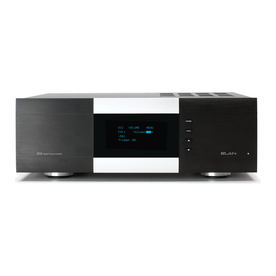
Identification of Controls Front Panel Front Panel Functions & Indicators Item Description Channel Selector Menu Up Selector Power LED Down Selector IR Icon Display Front Panel Functions & Indicators © ELAN Home Systems 2009 • All rights reserved. Page 1... -
Page 13: Rear Panel
+12V Channel Pair Trigger Inputs, Triggers 1-2, 3-4, 5-6, 7-8, 9-10, 11-12 +12V All On Trigger Input +12V Trigger Output IR Output IR Input VIA!NET Input/Output USB Mini B Port Power Cable Connector Rear Items & Connectors Page 2 © ELAN Home Systems 2009 • All rights reserved. -
Page 14: Rack Mounting
INSTALLATION MANUAL Rack Mounting When mounting the D12 in an equipment rack, use the included Rack Mount Brackets for secure mounting and proper ventilation. The D12 requires three rack spaces. To install the D12 into a standard 19” equipment rack: 1. -
Page 15: Operations & Settings
Operations & Settings Front Panel Controls The D12 front panel buttons provide control for the initial setup and amplifier status. Any button press activates the front panel LCD and displays the information until the LCD times out. Front Panel Controls Channel Button The Channel button toggles through all available channels as well as the ALL channel option. -
Page 16: Up & Down Arrow Buttons
Version, Diagnostics, Ambient Temperature, Save Dealer Defaults, and Restore Defaults. ELAN Mode The ELAN mode menu items are the same except for the following additional menu items that are after Output View: Absolute Max Volume, Min Turn On Volume, and Max Turn On Volume. -
Page 17: Normal Mode
When the MENU button is pressed for the first time, at Power ON, or after 50 seconds of no button activity, the Amplifier Status screen displays. The top of the screen displays what Mode you are in, either ELAN MODE or NORMAL MODE followed by the channels of this chassis I.E. CH1 - CH12. -
Page 18: Setting System Volume Levels
When AVR is active, AVR (Automatic Volume Reduction) is displayed above Volume %. AVR is active whenever the amp is being overdriven. When AVR is active, the D12 turns its volume down until it is not being overdriven. The D12 will turn its volume up when it is not being overdriven. -
Page 19: Input Select Menu
Overdriving the amplifier can damage the amplifier and void the manufacturer's warranty. Input Select Menu The INPUT SELECT menu will allow any or all of the D12's channels to be configured among six options: This example is with Channel 1 selected. - Page 20 All of the Odd channels (1, 3, 5, 7, 9, 11) are taken from Audio Input 1 which is Bus A and All of the Even chan- nels (2, 4, 6, 8, 10, 12) are taken from audio input 2 which is Bus A All Channel Selected © ELAN Home Systems 2009 • All rights reserved. Page 9...
-
Page 21: Channel Lock Menu
This menu allows any or all channels to be locked or unlocked after initial set-up selections have been determined. When locked, channel settings can not be altered even by IR Commands in ELAN mode. IndIvidual channels 1 - 12 options are LOCKED or UNLOCKED. -
Page 22: Power Saving Menu
Press the Channel button to change the channel. Press UP and DOWN buttons to change the Music Sense ON or Off. Press the Menu button to cycle to the beginning of the Main menu. © ELAN Home Systems 2009 • All rights reserved. Page 11... -
Page 23: Output View Menu
Press the MENU button to cycle to the next menu. Utility Menu The D12 features a Utility sub-menu that is designed to provide easy access to D12 operational functions. Whenever the LCD times out, the Utility menu resets to display the Operating Mode screen first. However, if... -
Page 24: Operating Mode
Places the D12 in either Normal Mode or ELAN Mode� Utility Menu-Operating Mode Press UP and DOWN buttons to select Normal Mode or ELAN Mode. Press the Channel button to cycle to the next Utility menu. Press the Menu button to cycle to the beginning of the Main menu. -
Page 25: Lcd Brightness
Press UP and DOWN buttons to change the LCD SLEEP TIMER. Press the Channel button to cycle to the next Utility menu. Press the Menu button to cycle to the beginning of the Main menu. Page 14 © ELAN Home Systems 2009 • All rights reserved. -
Page 26: Power Saving Mode
• The D12 may drop out in ALL ENABLED mode if the audio being sent to it is at a soft level (15%). This level may be audible to the human ear but the D12 thinks it is noise. Since the D12 thinks it is noise, the channel is turned off after 5 minutes. - Page 27 E L A N H O M E S Y S T E M S INSTALLATION MANUAL Power Saving Mode Menus Page 16 © ELAN Home Systems 2009 • All rights reserved.
-
Page 28: Firmware Version
Diagnostics Menu The Diagnostics menu provides easy access to current D12 system status. Diagnostics information displayed on the D12’s front panel include the number of times the unit has suffered fault conditions (F) and high temperatures (T) for each channel. -
Page 29: Ambient Temperature
E L A N H O M E S Y S T E M S INSTALLATION MANUAL Ambient Temperature This menu displays the current AMBIENT TEMPERATURE of the D12 chassis as well as minimum and maximum temperatures that are logged in memory. Ambient Temperature Menu Press UP and DOWN buttons to change from Celsius to Fahrenheit. - Page 30 Saving Dealer PIN: Retry Press the Menu button to CANCEL and cycle to the beginning of the Main menu. © ELAN Home Systems 2009 • All rights reserved. Page 19...
-
Page 31: Restore Defaults
Press UP and DOWN buttons to select CANCEL or Restore. Press the Channel button to commit the selection. If Restore is selected the D12 will immediately restore the selected defaults. Press the Menu button to cycle to the beginning of the Main menu. -
Page 32: Elan Mode
E L A N H O M E S Y S T E M S INSTALLATION MANUAL ELAN Mode The ELAN mode menu items are the same except for the following additional menu items that are after Output View: Absolute Max Volume, Min Turn On Volume, and Max Turn On Volume. -
Page 33: Minimum Turn-On Volume Menu
Channels can be turned off by IR Commands, from a Trigger Input or by turning the Power Switch OFF. Max Turn-On Volume Menu Press the Channel button to change the channel. Press UP and DOWN buttons to select the Maximum Turn-On Volume. Page 22 © ELAN Home Systems 2009 • All rights reserved. -
Page 34: Via!Net Address
16 chassis can be used for a total of 192 channels. D12s can have the same channel range settings if you want the D12s to respond to the same IR Commands. Channel Range Menu © ELAN Home Systems 2009 • All rights reserved. Page 23... -
Page 35: Fault Menu (For Both Normal And Elan Modes)
LCD. This message screen will remain in place until the fault condition has been attended to and the amplifier has been reset or repaired. Press the UP or DOWN buttons to reset the amplifier, if the amplifier doesn't reset, contact your dealer. Fault Menu Page 24 © ELAN Home Systems 2009 • All rights reserved. -
Page 36: Connections
INSTALLATION MANUAL Connections The D12 has many rear panel connections so it is important to label cables with their destination or source correctly. Use high quality line level RCA connector type cables for source connections to ensure the lowest possible noise and best sound performance. -
Page 37: Bus Inputs
INSTALLATION MANUAL BUS Inputs The D12 BUS Inputs A and B enables custom configuration of listening areas. Large or irregular shaped rooms may be configured for both mono and stereo as coverage is needed. Hallways, passageways, bathrooms and laundry rooms are the most popular areas that can benefit from a mono BUS application. BUS Input application examples are shown in the System Design section of this manual. -
Page 38: Speaker Binding Post
Speaker Binding Post The D12 is equipped with gold plated, 5-way speaker binding post. This will allow for five methods of speaker wire termination; bare wire, spade lug, pin, single banana and dual banana plug. Label all speaker wires with their desti- nation to ensure easy configuration. -
Page 39: Triggers
When the trigger is not active the channel pairs turn off. If no cables are used, the triggers will be turned on by default. S66A Zone Trigger Outputs to D12 Zone Trigger Inputs (Zones 1 & 3 Shown) 3.5mm mono... -
Page 40: All On Trigger Input
A 3.5mm mono interconnect cable is used for the ALL ON Trigger Input connection. This Turn-On Trigger activates ALL channels. When the trigger is active all channels turn on. When the trigger is not active all channels turn off. System Trigger Output to D12 All On Input 3.5mm mono interconnect cable... -
Page 41: Ir Loop Input/Output Connections
The 3.5mm mono IR Loop is located beside the ALL ON trigger. This loop allows IR commands to be sent to each D12 amplifier that is connected. Before the amplifier will respond to IR Commands, the D12 amplifier must be set to ELAN Mode. -
Page 42: Via!Net Loop Input/Output Connections
VIA!NET LOOP INPUT/OUTPUT Connections An RJ-45 VIA!NET Data Bus Loop is provided for feedback and amplifier status. Before the amplifier will pro- vide feedback, the D12 amplifier must be set to ELAN Mode with unique VIA!NET addresses for each "D series Amplifier."... -
Page 43: Usb Connector
E L A N H O M E S Y S T E M S INSTALLATION MANUAL USB Connector Used to update and configure the D12 firmware. Note: A Standard USB-A to USB-Mini-B cable must be utilized for firmware updates and is not included with the D12. -
Page 44: Applications
This example displays a basic stereo setup. Stereo from a source device is connected to audio inputs 1 and 2. Audio input 1 is routed to channel 1 and audio input 2 is routed to channel 2. Volume is adjusted by the ELAN System Controller or by the other Audio Device. From... - Page 45 Since Channel Range is set to 13 - 24, you must control the channel's volume using different commands. When a D12 is set to 13 to 24, the D12 is the second chassis in a two D12 chassis system. Page 34...
-
Page 46: Multiple Stereo Inputs
SPREAKER OUTPUTS (CLASS 2 WIRING) 75 W/CH @ 8 ohms 1440W INPUT T12.5 AL REPLACE WITH 9/10 11/12 SAME TYPE AND Model D12 RATING ONLY. +12VDC OUTPUT +12V TRIGGER INPUTS TRIGGER VIA!NET Digital Power Amplifier Multiple Stereo Inputs © ELAN Home Systems 2009 • All rights reserved. Page 35... -
Page 47: Single Stereo Input With Stereo And Mono Output
ELAN Legacy Standard application This is how you would have set up ELAN's previous amplifiers. This is NOT how ELAN recommends utilizing the D12. This is being shown to demonstrate the difference in legacy amplifiers and the D12. See "ELAN Special Application"... - Page 48 "Input Select Menu" on page 8 With the Input Select Menu set to the above settings, the D12 sums audio input 1 and 2 (Mono) and routes it to channel 3. The Y cable used in the previous example is not needed.
-
Page 49: Single Stereo Input With Stereo Out On Channels 1 - 8
ELAN Legacy Standard application This is how you would have set up ELAN's previous amplifiers. This is NOT how ELAN recommends utilizing the D12. This is being shown to demonstrate the difference in legacy amplifiers and the D12. See "ELAN Special Application"... - Page 50 The RCA jumpers from audio outputs 1 and 2 to audio inputs 3 and 4 and audio outputs 3 and 4 to audio inputs 5 and 6, and audio outputs 5 and 6 to audio inputs 7 and 8 are removed; the routing is performed in the D12.
- Page 51 E L A N H O M E S Y S T E M S INSTALLATION MANUAL Volume is adjusted by the ELAN System Controller or by the other Audio Device. Increasing or decreasing the volume increases stereo channels 1, 2, 3, 4, 5, 6, 7, and 8.
-
Page 52: Stand-Alone Stereo Bussing With Multiple Chassis
This example shows the preamp output of an A/V Receiver being distributed in a wide-area application, such as a great room. Speakers for both chassis are stereo for up to 12 pairs of speakers. © ELAN Home Systems 2009 • All rights reserved. Page 41... - Page 53 INPUT T12.5 AL 9/10 REPLACE WITH 11/12 SAME TYPE AND Model D12 RATING ONLY. +12VDC OUTPUT +12V TRIGGER INPUTS TRIGGER VIA!NET Digital Power Amplifier Multi-Channel Stereo Bussing D12 Settings Page 42 © ELAN Home Systems 2009 • All rights reserved.
-
Page 54: Multi-Room Stereo Zones
Prerequisites Factory defaulted The D12 is designed to easily power up to six independent stereo zones with any ELAN multi-room controller. This is the standard configuration for most multi-zone audio distribution systems. Each pair of speakers will have inde- pendent line-level volume control. -
Page 55: S128P Sub-Zones
"Restore Defaults" on page 20 "Operating Mode" on page 13 ELAN's S128P Multi-Room Controller has fixed preamp outputs for the addition of sub-zones. The sub zones can be amplified using rotary or electronic volume controls. The S128P increases or decreases the volume level for channels 1 and 2. - Page 56 Instead of using volume controls to have independent control of the volume in a zone and sub zone, control the channels of the D12 using IR Commands. Route the FIX out of the S128P to audio input 1 and audio input 2 (Bus The S128P increases or decreases the volume level for channels 1 and 2 Main Zone.
- Page 57 REPLACE WITH 11/12 SAME TYPE AND Model D12 RATING ONLY. +12VDC OUTPUT +12V TRIGGER INPUTS TRIGGER VIA!NET Digital Power Amplifier ZONE 1 ZONE 1 SUB-ZONE Sub-Zone wtih D12 Control Page 46 © ELAN Home Systems 2009 • All rights reserved.
-
Page 58: Troubleshooting
1. Turn switch On. Switch is located on the back Power Up of unit. 2. Circuit breaker tripped 2. Reset circuit breaker. The D12 draws 12A of AC current. Ensure that combined current draw of all devices on circuit does not exceed the circuit’s capacity. - Page 59 First notes of door chime from Power Save enabled Use 12V Zone Triggers or disable Power Save. C2 missing. Signal to rear fill channels cut See above See above in and out. Page 48 © ELAN Home Systems 2009 • All rights reserved.
- Page 60 Check IR receivers for ambient light or IR controller. IR Icon on LCD plasma TV flooding. flickers or is lit constantly. Incorrect channel and/or chas- Incorrect D12 IR commands Verify/correct IR programming. sis selected. programmed. © ELAN Home Systems 2009 • All rights reserved. Page 49...
-
Page 61: Specifications
21.32 Technical Support If, after carefully following the steps in the Troubleshooting section, you are unable to resolve issues with the installation or operation of the D12 Digital Power Amplifier, please call ELAN Technical Support at 1-800-622-ELAN (3526). Page 50... -
Page 62: Limited Warranty
ELAN in writing, ELAN shall repair or replace the item at the company’s option. This warranty shall not apply (a) to equipment not manufactured by ELAN, (b) to equipment which shall have been installed by other than an ELAN authorized installer, (c) to installed equipment which is not installed to ELAN’s specifications, (d) to equipment...
Need help?
Do you have a question about the D12 and is the answer not in the manual?
Questions and answers