Motorola Symbol MT2070 User Manual
Barcode scanner
Hide thumbs
Also See for Symbol MT2070:
- Isv manual (17 pages) ,
- User manual (606 pages) ,
- Quick start manual (2 pages)
Table of Contents
Advertisement
Quick Links
Advertisement
Table of Contents

Related Manuals for Motorola Symbol MT2070


Summary of Contents for Motorola Symbol MT2070
- Page 1 Symbol MT2070/MT2090 User Guide...
- Page 3 MT2070/MT2090 User Guide 72E-117859-02 Revision A September 2009...
-
Page 4: Patents
Motorola. No right to copy a licensed program in whole or in part is granted, except as permitted under copyright law. The user shall not modify, merge, or incorporate any form or portion of a licensed program with other program material, create a derivative work from a licensed program, or use a licensed program in a network without written permission from Motorola. -
Page 5: Revision History
Revision History Changes to the original manual are listed below: Change Date Description -01 Rev A 8/2009 Initial release. -02 Rev A 9/2009 Keypad, battery information and accessory updates. - Page 6 Symbol MT2070/MT2090 User Guide...
-
Page 7: Table Of Contents
Table of Contents Patents........................... iv Warranty ........................iv Revision History ......................v About This Guide Introduction ........................xix Documentation Set ....................xix Device Configurations....................xx Cradle Configurations ....................xx Chapter Descriptions ..................... xxi Notational Conventions....................xxii Related Documents ....................... xxiii Service Information...................... - Page 8 Battery Charging ......................1-14 Battery Safety ....................... 1-15 Security Implementation/Protection From Counterfeit Batteries ......1-15 Motorola Battery Safety Recommendations For Users ........... 1-15 Proper and Safe Battery Disposal & Recycling: ............1-16 Sending Data to the Host Computer ................1-17 Cable Mode ......................
- Page 9 Table of Contents Suspend ......................2-16 Scan Item ........................2-17 Quantity ........................2-17 Item ......................... 2-17 Menu ........................2-18 Options ......................2-18 About......................... 2-19 Close ......................... 2-19 Close ........................2-19 Scan Inventory ......................2-20 Location ........................2-20 Quantity ........................2-21 Item .........................
- Page 10 Symbol MT2070/MT2090 User Guide Manage PACs ....................2-64 Options ......................2-67 Wireless Status ....................2-73 Wireless Diagnostics ..................2-78 Log On/Off ......................2-82 Enable/Disable Radio ..................2-83 Settings ........................2-84 General Parameters ..................2-84 Bar Code Settings ..................... 2-84 Rapid Deployment ....................2-85 MSP Agent ......................
- Page 11 Table of Contents Wireless Beeper Definitions ..................4-3 Radio Communications Host Types ................4-4 Bluetooth Technology Profile Support ................4-6 Master/Slave Set Up ....................4-6 Master ....................... 4-6 Slave ......................... 4-6 Bluetooth Friendly Name ..................4-7 Discoverable Mode ....................4-7 HID Host Parameters ....................
- Page 12 Symbol MT2070/MT2090 User Guide Set Default Parameter .................... 5-4 Host Mode ....................... 5-5 Decode Pager Motor Enable ................... 5-6 Parameter Bar Code Scanning ................5-7 Beep After Good Decode ..................5-7 Beeper Tone ......................5-8 Beeper Volume ....................... 5-9 Hand-Held Trigger Mode ..................5-10 Decode Session Timeout ..................
- Page 13 Table of Contents xiii Chapter 7: Customizing the MT20X0 Introduction ........................7-1 Customizing the Startup Program ................. 7-2 Customizing the Home Screen View ................7-3 Navigator.xml File Content ..................7-4 Customizing the Scan Item or Scan Inventory Program ..........7-5 Disabling MT2000 Scanner Services ................
- Page 14 Symbol MT2070/MT2090 User Guide Chapter 10: IBM 468X / 469X Interface Introduction ........................10-1 Connecting to an IBM 468X/469X Host ................ 10-2 IBM Parameter Defaults ....................10-3 IBM 468X/469X Host Parameters ................. 10-4 Port Address ......................10-4 Convert Unknown to Code 39 ................. 10-5 Chapter 11: Keyboard Wedge Interface Introduction ........................
- Page 15 Table of Contents UPC-E1 Preamble ....................12-16 Convert UPC-E to UPC-A ..................12-17 Convert UPC-E1 to UPC-A ..................12-17 EAN-8/JAN-8 Extend ....................12-18 Bookland ISBN Format ................... 12-19 UCC Coupon Extended Code ................. 12-20 Code 128 ........................12-21 Enable/Disable Code 128 ..................12-21 Set Lengths for Code 128 ..................
- Page 16 Symbol MT2070/MT2090 User Guide Postal Codes ........................ 12-49 US Postnet ......................12-49 US Planet ........................ 12-50 Transmit US Postal Check Digit ................12-50 UK Postal ........................ 12-51 Transmit UK Postal Check Digit ................12-51 Japan Postal ......................12-52 Australian Postal ..................... 12-52 Netherlands KIX Code ...................
- Page 17 Table of Contents xvii LED Indicators ......................13-4 Miscellaneous LED Indicator Information ............13-4 Four Slot Cradles ......................13-5 Cradle Features ...................... 13-5 Inserting Devices and Batteries in the Cradle ............13-5 Sending Data to the Host Computer ............... 13-5 Charging .........................
- Page 18 Symbol MT2070/MT2090 User Guide Send Preset Value .................... 14-34 Modify Data ......................14-35 Remove All Spaces ................... 14-35 Crunch All Spaces .................... 14-35 Stop Space Removal ..................14-35 Remove Leading Zeros ..................14-35 Stop Zero Removal ................... 14-35 Pad Data with Spaces ..................... 14-36 Pad Data with Zeros ....................
- Page 19 Table of Contents Appendix C: Sample Bar Codes UPC-A ........................... C-1 UPC-E ........................... C-1 UPC-E1 ......................... C-2 EAN-13 ......................... C-2 EAN-8 ........................... C-2 Code 39 ........................C-2 Trioptic Code 39 ......................C-3 Code 93 ........................C-3 Code 11 ........................C-3 Code 128 ........................
- Page 20 Symbol MT2070/MT2090 User Guide...
-
Page 21: About This Guide
This guide provides information about using the Symbol MT2070/MT2090 devices. NOTE Screens and windows pictured in this guide are samples and can differ from actual screens. Documentation Set The documentation set for the Symbol MT2070/MT2090 devices provides information for specific user needs, and includes:/ •... -
Page 22: Device Configurations
Symbol MT2070/MT2090 User Guide Device Configurations Operating Configuration Radios Display Memory Data Capture Keypads System MT2090-SL0D6 802.11/Bluetooth 320x240 64 MB RAM 1D, Standard Windows CE 5.0 21 key 2170WR Color 64 MB Flash Range, WW MT2090-SD0D 802.11/Bluetooth 320x240 64 MB RAM 1D/2D, Standard Windows CE 5.0... -
Page 23: Chapter Descriptions
About This Guide Chapter Descriptions Topics covered in this guide are as follows: • Chapter 1, Getting Started provides a product overview, unpacking instructions and start up information. • Chapter 2, Operating the MT2070/MT2090 describes the device’s screens, and how to use the device. •... -
Page 24: Notational Conventions
Symbol MT2070/MT2090 User Guide Notational Conventions The following conventions are used in this document: • Italics are used to highlight the following: • Chapters and sections in this and related documents • Bold text is used to highlight the following: •... -
Page 25: Related Documents
Figure 2-10 on page 2-16. Motorola responds to calls by E-mail, telephone or fax within the time limits set forth in support agreements. If your problem cannot be solved by Motorola Enterprise Mobility Support, you may need to return your equipment for servicing and will be given specific directions. - Page 26 Symbol MT2070/MT2090 User Guide...
-
Page 27: Chapter 1 Getting Started
(if purchased). Unpacking Carefully remove all protective material from around the equipment and inspect it for damage. If the equipment was damaged in transit, contact Motorola Enterprise Mobility Support. See page xxiii for contact information. KEEP THE PACKING. -
Page 28: Stb2000-F10007R Forklift Single Slot Charge Only
1 - 2 Symbol MT2070/MT2090 User Guide STB2000-F10007R Forklift Single Slot Charge Only Verify that the equipment listed below is included in the box: • Cradle with forklift cup installed • Metal mounting bracket with isolators • Quick Reference Guide. -
Page 29: Features
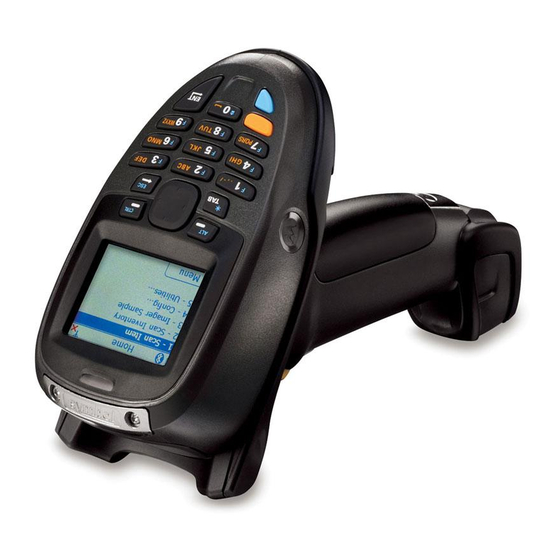
Getting Started 1 - 3 Features Scan LED Display Keypad Scan LED (MT2090 only) Scan LED Scan (MT2090 only) Window * Accessory Port Cover Scan Trigger Battery Battery Latch Lanyard * Note: The accessory port is not available for use at this Catch time. -
Page 30: Cradle Features
1 - 4 Symbol MT2070/MT2090 User Guide Cradle Features Single Slot - Front View and Connections Horizontal Desk Mounting Pairing Bar Code (Bluetooth cradles only) Note: An additional Pairing Bar Code is affixed under the cup. Power USB/Host Connector Connector NOTE The functionality of the USB connection to a host PC varies by cradle type. -
Page 31: Single Slot - Back View
Getting Started 1 - 5 Single Slot - Back View Mounting Key-Hole Forklift Bracket Forklift Bracket Screw Hole Screw Hole Rubber Rubber Foot Foot Cable Ferrite Hook Power Cable USB/Host Groove Cable Groove Release WARNING Never connect an Snaps Host Port Ethernet or phone cable to the host interface Power Port... -
Page 32: Single Slot - Mounting Cups
1 - 6 Symbol MT2070/MT2090 User Guide Single Slot - Mounting Cups Desk Mount Cup Forklift Cup Wall Mount Cup Single Slot Cradle - Mounting Cups Figure 1-4... -
Page 33: Four Slot - Front View And Connections
Getting Started 1 - 7 Four Slot - Front View and Connections Ethernet Activity LEDs (Ethernet Charging/ cradles only) Cradle Communications Battery Power Contacts Charging LED Battery (four) Charging Device Well Battery Contacts (four) Well (four) Wall Mounting Interchangeable Latches (two in Desk/Wall Mount each well) Cup (four) -
Page 34: Four Slot - Back View
1 - 8 Symbol MT2070/MT2090 User Guide Four Slot - Back View Primary Ethernet Secondary Ethernet Mounting Port (Ethernet port for daisy chain Mounting Hole Power Port cradle only) (Ethernet cradle only) Hole Wall Mount Cup Screws Mounting Hole Mounting... -
Page 35: Four Slot Spare Battery Charger
Getting Started 1 - 9 Four Slot Spare Battery Charger Cradle Battery Battery Power Charging LED Charging (four) Contacts Battery Well (four) Power Cable Groove Wall Mount Key-Hole (4) Cable Well Rubber Feet Power Port Four Slot Spare Battery Charger Figure 1-7... -
Page 36: Host Interfaces
1 - 10 Symbol MT2070/MT2090 User Guide Host Interfaces This device supports the following host interfaces through communication with a single slot multi-interface cradle: • Standard RS-232 connection to a host. • Keyboard wedge connection to a host, where scanned data is interpreted as keystrokes. The following international keyboards are supported (for Windows™... -
Page 37: Insert The Battery
Getting Started 1 - 11 Insert the Battery The battery resides in a chamber in the device handle. NOTE If the battery is completely discharged, and the unit is powered from a USB or RS232 cable, it may take up to two hours for the unit to power up.There is no indication to the user of this condition and it may appear that the unit is not charging and/or not working correctly. -
Page 38: Connecting Stb2000-F Cradle
1 - 12 Symbol MT2070/MT2090 User Guide If necessary, scan the appropriate host bar code (for non-autodetected interfaces). See the specific host chapter. NOTE Disconnect the power supply before changing host cables, or the device may not recognize the new host. -
Page 39: Insert The Device In The Cradle
3-3). If the device displays indicating a charging problem, remove the device from the cradle and replace the battery. If one of these icons continues to display, contact Motorola Enterprise Mobility Support. See Screen Icons on page 2-9 for descriptions of display icons. -
Page 40: Battery Charging
Use a cradle or a charge cable to charge the Li-ion battery in the device. Use either the four slot cradle or four slot battery charger to charge up to four spare batteries. The charge cable requires a Symbol/Motorola approved power supply. -
Page 41: Battery Safety
IMPORTANT Battery safety depends on the proper selection and care of batteries. Security Implementation/Protection From Counterfeit Batteries Motorola devices are designed to work only with Motorola batteries. If you see a battery fault indication on the device display, take the following steps: •... -
Page 42: Proper And Safe Battery Disposal & Recycling
1 - 16 Symbol MT2070/MT2090 User Guide Proper and Safe Battery Disposal & Recycling: Proper battery disposal is not only important for safety, it also benefits the environment. Promptly dispose of used batteries in accordance with local regulations. Contact your local recycling center or national recycling organizations for more information on how to dispose of batteries. -
Page 43: Sending Data To The Host Computer
Getting Started 1 - 17 Sending Data to the Host Computer Out of the box, the device supports two modes to send data to a host computer: via cable (RS-232 or USB); and via Bluetooth (open/paired with an STB2078 cradle). Cable Mode Via cable (RS-232 or USB) the user interface indicates the active mode for transmitting bar code data to the host. -
Page 44: Radio Communications
1 - 18 Symbol MT2070/MT2090 User Guide Radio Communications The device can communicate with remote devices via Bluetooth Technology Profile Support, or by pairing with a cradle. For radio communication parameters, detailed information about operational modes, Bluetooth Technology Profile Support and pairing, see Chapter 4, Radio Communications. -
Page 45: Battery Removal
Getting Started 1 - 19 Battery Removal To remove the battery: Press Menu >Suspend to turn off the screen and place the device in suspend mode. With your thumb, press down on the indentation on the battery lock and drag it away from the battery. Lift up the back of the battery and pull it out of the battery well. -
Page 46: Lanyard
1 - 20 Symbol MT2070/MT2090 User Guide Lanyard To install the optional lanyard: Insert the loop on the lanyard into the slot at the bottom of the device. Insert Lanyard Loop Figure 1-12 Thread the upper portion of the lanyard into the loop. -
Page 47: Screen Protector
Getting Started 1 - 21 Screen Protector For added protection from scratches the device includes a protective film over the display window. It is recommended you leave this on for added scratch resistance. - Page 48 1 - 22 Symbol MT2070/MT2090 User Guide...
-
Page 49: Chapter 2 Operating The Mt2070/Mt2090
Chapter 2 Operating the MT2070/MT2090 Introduction This chapter provides instructions for using and navigating the device. -
Page 50: Keypad
2 - 2 Symbol MT2070/MT2090 User Guide Keypad The keypad contains alphanumeric characters, scroll keys, function keys and an ENT (Enter) key. The keypad is color-coded to indicate the alternate function keys (blue and orange). Note that an application can change the keypad functions so the device's keypad may not function exactly as described. -
Page 51: Keypad Functionality
Operating the MT2070/MT2090 2 - 3 Keypad Functionality Keypad Functionality Table 2-1 Press Blue Press Orange Description Left Soft Key, ALT Defaults to the left soft key which initiates the action noted on the bottom left of the screen (usually a menu option); ALT key when the Blue function key is enabled. - Page 52 2 - 4 Symbol MT2070/MT2090 User Guide Keypad Functionality (Continued) Table 2-1 Press Blue Press Orange Description F3, 3, D, E, F, d, e, f Defaults to the number 3; F3 when the Blue function key d, e, f, D, E, F is enabled;...
- Page 53 Operating the MT2070/MT2090 2 - 5 Keypad Functionality (Continued) Table 2-1 Press Blue Press Orange Description F6, 6, M, N, 0, m, n, o Defaults to the number 6; F6 when the Blue function key m, n, o, M, N, 0 is enabled;...
- Page 54 2 - 6 Symbol MT2070/MT2090 User Guide Keypad Functionality (Continued) Table 2-1 Press Blue Press Orange Description F9, 9, W, X, Y, Z, w, x, y, z Defaults to the number 9; F9 when the Blue function key w, x, v, z, W, X, is enabled;...
- Page 55 Operating the MT2070/MT2090 2 - 7 Keypad Functionality (Continued) Table 2-1 Press Blue Press Orange Description Press ENT (Enter) to launch an application or select a current/highlighted item. Depending on the screen, press Enter to: • close a display and return to the previous screen. •...
-
Page 56: Using The Keypad To Navigate Applications
2 - 8 Symbol MT2070/MT2090 User Guide Using the Keypad to Navigate Applications The screen is a non-touch screen. Navigation and control of an application is performed using the keypad. Entering Information To enter information: • Use the keypad. •... -
Page 57: Screen Icons
Operating the MT2070/MT2090 2 - 9 Screen Icons Icons Table 2-2 Icon Description Battery Critical low battery (< 5% full); recharge. Battery fault. Battery fault; AC power applied. Low battery; recharge. Low battery; recharge. Battery is 25% full. Battery is 50% full. Battery is 75% full. - Page 58 2 - 10 Symbol MT2070/MT2090 User Guide Icons (Continued) Table 2-2 Icon Description Connections Bluetooth is inactive (STB2078 cradle only). Bluetooth is active (STB2078 cradle only). RS-232 connection is active. USB connection is active. Keypad Functionality One time blue key functionality (see Blue on page 2-7).
-
Page 59: Home Screen
Operating the MT2070/MT2090 2 - 11 Home Screen When the device powers on, the first screen to display is the Home screen. This screen also launches when you press the Home key (see Home, 0, space on page 2-6). MT2090 MT2070 Home Screen Figure 2-2... -
Page 60: Menu
2 - 12 Symbol MT2070/MT2090 User Guide Home Screen Options (Continued) Table 2-3 Option Description Config... On this screen the user has access to the following features: • Wireless Companion - see page 2-32. • Settings - see page 2-84. -
Page 61: User Settings
Operating the MT2070/MT2090 2 - 13 User Settings On this screen, make adjustments for the device’s beeper, backlight and time. Press the Up or Down Scroll key to select an option. User Settings Screen Figure 2-4 • Beeper Volume: Scroll to Beeper Volume and press the right or left Scroll key to choose a Low, Medium or High beeper volume. - Page 62 2 - 14 Symbol MT2070/MT2090 User Guide • Date and Time: With Date and Time highlighted, press ENT to display the Date and Time screen. Date and Time Screen Figure 2-6 • Press TAB to toggle between Date: and Time: fields.
-
Page 63: Device Status
Operating the MT2070/MT2090 2 - 15 Device Status This screen displays model, serial number, bluetooth and MAC address information about the device. Device Status Screen Figure 2-8 NOTE MAC: field applies to the MT2090 only. Battery Status This screen displays the device’s battery information. Battery Status Screen Figure 2-9... -
Page 64: About
2 - 16 Symbol MT2070/MT2090 User Guide About This screen displays version and copyright information. About Screen Figure 2-10 Suspend On the Home screen (see Figure 2-2 on page 2-11) press Menu > Suspend to place the device in sleep mode. To... -
Page 65: Scan Item
Operating the MT2070/MT2090 2 - 17 Scan Item The Scan Item screen allows the user to transmit bar code data to the host PC. To access Scan Item, start at the Home screen, scroll to Scan Item and press ENT. Scan Item Screen Figure 2-11 The following options are available:... -
Page 66: Menu
2 - 18 Symbol MT2070/MT2090 User Guide Menu Press the left soft key to display the Menu. Scan Item Screen - Menu Figure 2-12 Options Scroll to Options... and press ENT to display the options screen to set transmit bar code data options. -
Page 67: About
Operating the MT2070/MT2090 2 - 19 About... Displays information about the ScanItem application. Close Press the right soft key to close the screen and return Home. Close Scroll to Close and press ENT to exit and return Home. -
Page 68: Scan Inventory
2 - 20 Symbol MT2070/MT2090 User Guide Scan Inventory The Scan Inventory screen allows the user to enter inventory information and send it to a local file in the Windows CE file system. Set the file type in which to save the inventory data in Menu > Options screen > Format: (see Figure 2-16 on page 2-21). -
Page 69: Quantity
Operating the MT2070/MT2090 2 - 21 Quantity Quantity defaults to a value of one to transmit one bar code to the host PC. Scroll to Quantity and use the keypad to enter the quantity of SKUs or bar code data to transmit to the host PC (0 to 99999). - Page 70 2 - 22 Symbol MT2070/MT2090 User Guide View Inventory Menu The View Inventory menu includes several options to maintain and customize inventory data. On the View Inventory screen press the left soft key to display the menu items. Press the Up or Down Scroll key to select an option.
- Page 71 Operating the MT2070/MT2090 2 - 23 • Delete Item Ensure the item to delete is highlighted on the View Inventory screen, then press Menu > Delete Item..The following confirmation dialog displays. Press the left soft key (No) to cancel the delete and return to the View Inventory screen.
- Page 72 2 - 24 Symbol MT2070/MT2090 User Guide • Export Exporting formats data in a user friendly layout which can be downloaded from the device. On the View Inventory screen, press Menu > Export. The dialog in Figure 2-21 displays indicating the path of the file to be exported to the Application folder on the device.
- Page 73 Operating the MT2070/MT2090 2 - 25 Options... Scroll to Options and press ENT to configure the inventory application. On this screen, set the file format and the file storage location to save data. The format is specified in an xml file located in the folder \application\inventory. Press the Up or Down Scroll key to move from field to field.
-
Page 74: Mcl
2 - 26 Symbol MT2070/MT2090 User Guide When you select MCL from the Home screen, the MCL-Client loads and the MCL program which loaded on the device runs. MCL-CIient Load - Typical View Figure 2-24 By default, the MCL application on the device is a simple scanning application which performs scanning and sending bar codes to a host computer, and scanning inventory with a timestamp. -
Page 75: Scan Transmit
Operating the MT2070/MT2090 2 - 27 Scan Transmit When Scan Transmit is selected on the Main Menu, the Scan & Send screen displays. On this screen the user can manually enter a quantity and scan data to a computer using a tethered cable or a Bluetooth connection via the STB2078 cradle. -
Page 76: Scan Inventory
2 - 28 Symbol MT2070/MT2090 User Guide Scan Inventory When Scan Inventory is selected on the Main Menu, the Scan Inventory screen displays (Figure 2-27). On this screen the user must enter the location in which the inventory is scanned. When a location is not entered, two short beeps sound indicating an error. -
Page 77: View Data
Operating the MT2070/MT2090 2 - 29 Use the right soft key to select MENU. The Inventory Menu displays. Inventory Menu Screen Figure 2-29 Select the appropriate option and press the right soft key (OK) to perform the appropriate action (View Data, Send Data,... -
Page 78: Image Viewer (Devices Equipped With Imagers)
2 - 30 Symbol MT2070/MT2090 User Guide Image Viewer (Devices Equipped with Imagers) The Image Viewer screen allows the user to preview, snap and save images. To access Imager Sample, start at the Home screen, scroll to Imager Sample and press ENT... -
Page 79: Options
Operating the MT2070/MT2090 2 - 31 Options Scroll to Options and press ENT to display the Options screen. Press the up or down Scroll key to select an option to edit and press ENT. Options Screen Figure 2-33 • JPEG Quality: Picture quality indicator. Higher numbers produce better quality pictures and larger file sizes). •... -
Page 80: Config
2 - 32 Symbol MT2070/MT2090 User Guide Config To access Config, start at the Home screen, scroll to Config... and press ENT. MT2070 MT2090 Config... Screens Figure 2-34 Wireless Companion (MT2090 Only) NOTE Some screens and windows pictured in this section are samples and can differ from actual screens. -
Page 81: Find Wlans
Operating the MT2070/MT2090 2 - 33 Find WLANs On the Wireless Companion menu, press the up or down Scroll key to highlight Find WLANs and press ENT to display the Find WLANs screen. Find WLANs Screen Figure 2-36 The Find WLANs list displays: •... -
Page 82: Creating A New Profile
2 - 34 Symbol MT2070/MT2090 User Guide Icons next to each profile identify the profiles current state. Profile Icons Table 2-4 Icon Description No Icon Profile is not selected, but enabled. Profile is disabled. Profile is Cancelled. A Cancelled profile is disabled until a connect or login function is performed through the configuration editor. -
Page 83: Profile Id
Operating the MT2070/MT2090 2 - 35 Profile ID Press the up or down Scroll key on the profile menu and select Add. The Profile Entry dialog displays. Profile Entry Screen Figure 2-38 Profile Name The name and (WLAN) identifier of the network connection. Enter a user friendly name for the device profile used to connect to either an AP or another networked device. - Page 84 2 - 36 Symbol MT2070/MT2090 User Guide Operating Mode Select the operating mode (Infrastructure or Ad-Hoc) from the Operating Mode: drop-down list. The operating mode Infrastructure enables the device to transmit and receive data with an AP. Infrastructure is the default mode.
-
Page 85: Channel
Operating the MT2070/MT2090 2 - 37 Channel If Ad-Hoc mode was selected the Ad-Hoc Channel dialog displays. Ad-Hoc - Channel Screen Figure 2-40 Use the Ad-Hoc Channel dialog to configure the required information to create an Ad-Hoc profile. This dialog does not appear if you selected Infrastructure mode. -
Page 86: Security Mode
2 - 38 Symbol MT2070/MT2090 User Guide Security Mode If Infrastructure mode was selected the Security Mode dialog displays. Infrastructure - Security Mode/Authentication Type Figure 2-41... -
Page 87: Security Mode
Operating the MT2070/MT2090 2 - 39 Security Mode Use the Security Mode dialog to configure the Security and Authentication methods. If Ad-Hoc mode is selected, this dialog is not available and authentication is set to None by default. Select the security mode from the Security Mode drop-down list. The selection chosen affects the availability of other choices for Authentication Type and Encryption methods. -
Page 88: Authentication Type
2 - 40 Symbol MT2070/MT2090 User Guide Authentication Type Select an available authentication type from the drop-down list. The options listed in the drop-down list are based on the selected Security Mode as shown in Table 2-8. The authentication types, other than None, all use IEEE 802.1x authentication to ensure that only valid users and sometimes servers can connect to the network. - Page 89 Operating the MT2070/MT2090 2 - 41 To select a tunneled authentication type: Select a tunneled authentication type from the drop-down list. See Table 2-9 for the Tunnel Authentication options for each authentication type. Select the User Certificate check box if a certificate is required. If the TLS tunnel type that requires a user certificate is selected, the check box is already selected.
-
Page 90: User Certificate Selection
2 - 42 Symbol MT2070/MT2090 User Guide Tunneled Authentication Options (Continued) Table 2-9 Authentication Type Tunneled Authentication PEAP TTLS EAP-FAST Description MS CHAP v2 Microsoft Challenge Handshake Authentication Protocol version 2 (MS CHAP v2) is a password-based, challenge-response, mutual authentication protocol that uses the industry-standard Message Digest 4 (MD4) and Data Encryption Standard (DES) algorithms to encrypt responses. - Page 91 Operating the MT2070/MT2090 2 - 43 User Certificate Installation There are two methods available to install a user certificate for authentication. The first is to obtain the user certificate from the Certificate Authority (CA). This requires connectivity with that CA. The second method is to install the user certificate from a file that was placed on the device.
- Page 92 2 - 44 Symbol MT2070/MT2090 User Guide To install a user certificate from a file: Tab to Install Certificate and press ENT. The Import Certificate dialog displays. Import Certificate Dialog Box Figure 2-46 Choose Import from File and select OK. The Open dialog displays.
- Page 93 Operating the MT2070/MT2090 2 - 45 Enter the password and select OK. The certificate(s) are imported. NOTE Installing a user certificate from a file requires that the file be of type “*.pfx”. Also this file type requires the user to supply a password in order to be read by Fusion. Server Certificate Selection If the user selects the Validate Server Certificate check box, a server certificate is required.
- Page 94 2 - 46 Symbol MT2070/MT2090 User Guide A dialog displays that lists the certificate files found with the default extension. Open Screen Figure 2-51 Browse to the file and select OK. A confirmation dialog verifies the installation. If the information in this dialog is correct, select Yes. If the information in this dialog is not correct select No.
- Page 95 Operating the MT2070/MT2090 2 - 47 dialog, it is cached as usual, but it is not be used to initialize the username field the next time the interactive credential dialog is shown for that profile; the username field is initialized to blank. In summary, the user can control whether the username field in the interactive credential dialog is initialized, either with the last-interactively-entered username for that profile or with the username entered into the profile, by whether any value is entered in the Enter User Name field during profile entry.
-
Page 96: Advanced Identity
2 - 48 Symbol MT2070/MT2090 User Guide Two radio buttons are added to allow the user to choose a token or static password. Choose the Token radio button when using the profile in conjunction with a token generator (hardware or software). -
Page 97: Credential Cache Options
Operating the MT2070/MT2090 2 - 49 Credential Cache Options If the user selected any of the password-based authentication types then different credential caching options are available. These options specify when the network credential prompts appear: at connection, on each resume or at a specified time. - Page 98 2 - 50 Symbol MT2070/MT2090 User Guide NOTE Entering credentials applies the credentials to a particular profile. Logging out clears all cached credentials. Editing a profile clears any cached credentials for that profile. Users who configure their APs to use the Fast Session Resume capability available with some Authentication Types (e.g., PEAP) should not check At Connect or On Resume if they wish to avoid being...
-
Page 99: Encryption
Operating the MT2070/MT2090 2 - 51 Tab to Next > and press ENT. The At Time dialog displays. At Time Dialog Box Figure 2-59 Enter the time using the 24 hour clock format in the (hh:mm) text box. Select > to move the time to the right. Repeat for additional time periods. Tab to Next >... - Page 100 2 - 52 Symbol MT2070/MT2090 User Guide Encryption Options Table 2-11 Encryption Description Open Select Open (the default) when no data packet encryption is needed over the network. Selecting this option provides no security for data transmitted over the network.
- Page 101 Operating the MT2070/MT2090 2 - 53 Encryption / Authentication Matrix (Continued) Table 2-12 Authentication Encryption WPA2 Legacy (Pre-WPA) WPA Enterprise WPA2 Enterprise Personal Personal Open TKIP TKIP PEAP WEP-104 LEAP WEP-104 TTLS WEP-104 If either WEP-40 (40/24) or WEP-104 (104/24) is selected, the wizard displays the key entry dialog unless the Use Passkey check box was selected in the Encryption dialog (see Figure 2-54 on page 2-47).
- Page 102 2 - 54 Symbol MT2070/MT2090 User Guide For WEP only, in the Transmit Key drop-down list, select the key to transmit. Tab to Next > and press ENT. The IP Address Entry dialog displays. To enter a hexadecimal key without characters hidden: Tab to Next >...
- Page 103 Operating the MT2070/MT2090 2 - 55 To enter a pass-phrase with characters hidden: Select the For added security - Mask characters entered check box. Tab to Next > and press ENT. WEP-40 and WEP-104 WEP Keys Dialog Boxes Figure 2-63 In the Key field, enter the key.
-
Page 104: Ip Address Entry
2 - 56 Symbol MT2070/MT2090 User Guide IP Address Entry Use the IPv4 Address Type dialog to configure network address parameters: IP address, subnet mask, gateway, DNS and WINS. IPv4 Address Type Dialog Box Figure 2-65 IP Address Entry Table 2-13... - Page 105 Operating the MT2070/MT2090 2 - 57 Static IP Address Entry Fields Table 2-14 Field Description IP Address The Internet is a collection of networks with users that communicate with each other. Each communication carries the address of the source and destination networks and the particular machine within the network associated with the user or host computer at each end.
-
Page 106: Transmit Power
2 - 58 Symbol MT2070/MT2090 User Guide Transmit Power The Transmit Power drop-down list contains different options for Ad-Hoc and Infrastructure mode. Automatic (i.e., use the current AP settings) and Power Plus (use higher than the current AP settings) are available for Infrastructure mode. -
Page 107: Battery Usage
Operating the MT2070/MT2090 2 - 59 Power Transmit Options (Ad-Hoc Mode) Table 2-17 Field Description Full Select Full power for the highest transmission power level. Select Full power when operating in highly reflective environments and areas where other devices could be operating nearby or when attempting to communicate with devices at the outer edge of a coverage area. -
Page 108: Manage Certificates
2 - 60 Symbol MT2070/MT2090 User Guide Battery Usage Options Table 2-18 Field Description Continuous Aware Mode (CAM) provides the best network performance, but yields the shortest battery life. Fast Power Save Fast Power Save (the default) performs in the middle of CAM and MAX Power Save with respect to network performance and battery life. - Page 109 Operating the MT2070/MT2090 2 - 61 Various certificate types display at one time. Select the Certificate Type drop-down box to filter the certificate list to display All, only Root/Server or only User/Client certificates. Certificate Type Options Screen Figure 2-72 The Certificate Manager screen contains command buttons at the bottom of the screen. A button might be disabled (gray) if the operation cannot be performed based on any selected object.
- Page 110 2 - 62 Symbol MT2070/MT2090 User Guide Certificate Properties To display the detailed properties of a certificate, select a certificate in the list, press ENT to display the menu and select Properties. The screen displays the properties of the certificate. Select a property in the upper list and the detailed information displays in the Expanded Value section.
- Page 111 Operating the MT2070/MT2090 2 - 63 Select the Import from File (.cer, .pfx) radio button to import a certificate file. The Open screen displays. Select the file to import. Certificate Manager Screen Figure 2-76 Select the Import User Cert from Server radio button to import a certificate from a server. The Install From Server screen displays.
-
Page 112: Manage Pacs
2 - 64 Symbol MT2070/MT2090 User Guide Manage PACs Users can view and manage Protected Access Credentials (PACs) used by Cisco’s EAP-FAST authentication protocol. On the Wireless Companion menu scroll to Manage PACs and press ENT. The PAC Manager screen displays. - Page 113 Operating the MT2070/MT2090 2 - 65 PAC Properties Display the detailed properties of a PAC by selecting an item in a sub-tree and selecting Properties or pop-up menu. The following screen displays with the list of properties in the upper portion of the screen. By selecting an entry in the upper list, the expanded details of the entry property displays in the lower list of the screen.
- Page 114 2 - 66 Symbol MT2070/MT2090 User Guide Navigate to the file to be imported and choose it. The Import PAC dialog displays. Import PAC Dialog Box Figure 2-83 If the PAC file is password protected, enter the password in the Password field. If you clear the Hide Password check box, the password is displayed in clear text as you type it.
-
Page 115: Options
Operating the MT2070/MT2090 2 - 67 Options Use the Wireless Options dialog to select one of the following operation options from the drop-down list: • Operating Mode (Op Mode) Filtering • Regulatory • Band Selection • System Options • Auto PAC Settings •... - Page 116 2 - 68 Symbol MT2070/MT2090 User Guide Regulatory Options Use the Regulatory settings to configure the country the device is in. Due to regulatory requirements (within a country) a device is only allowed to use certain channels. Regulatory Options Dialog Box...
- Page 117 Auto Time Config Enables automatic update of the system time. Network association updates the device time based on the time set in the AP. This proprietary feature is only supported with Motorola infrastructure. Enabled by default. Use the Auto PAC Settings to configure whether to allow automatic PAC provisioning and automatic PAC...
- Page 118 2 - 70 Symbol MT2070/MT2090 User Guide Auto PAC Settings Dialog Box Figure 2-89 Auto PAC Settings Table 2-23 Field Description Allow Provisioning Select Yes from the drop-down list to allow the terminal to be automatically provisioned with a PAC when using the EAP-FAST authentication protocol.
- Page 119 Operating the MT2070/MT2090 2 - 71 To delete the password, enter the current password in the Current: text box and leave the New: and Confirm: text boxes empty. Select Save. NOTE Passwords are case sensitive and can not exceed 63 characters.
- Page 120 2 - 72 Symbol MT2070/MT2090 User Guide Export NOTE For Windows CE 5.0 devices, exporting options enables settings to persist after a cold boot. Use Export to export all profiles to a registry file and to export the options to a registry file.
-
Page 121: Wireless Status
Operating the MT2070/MT2090 2 - 73 To export all profiles: Select Export All Profiles. The Save As dialog displays. Export All Profiles Save As Dialog Box Figure 2-93 Enter a filename in the Name: field. The default filename is WCS_PROFILES.REG. In the Folder: drop-down list, select the desired folder. - Page 122 2 - 74 Symbol MT2070/MT2090 User Guide • Versions: Displays software, firmware and hardware version numbers. • Quit: Exits the Wireless Status screen. Each option screen contains a back button to return to the main Wireless Status screen. Signal Strength The Signal Strength screen provides information about the connection status of the current wireless profile including signal quality, missed beacons and other statistics described below.
- Page 123 Operating the MT2070/MT2090 2 - 75 Signal Strength Status (Continued) Table 2-24 Field Description Tx Retries Displays a percentage of the number of data packets the device retransmits. The fewer transmit retries, the more efficient the wireless network is. Missed Beacons Displays a percentage of the amount of beacons the device missed.
- Page 124 2 - 76 Symbol MT2070/MT2090 User Guide Current Profile Screen (Continued) Table 2-25 Field Description Channel Displays the channel currently being used to communicate with the AP. Country Displays the country setting currently being used. Transmit Power Displays the current radio transmission power level. See Table 2-17 on page 2-59.
- Page 125 Operating the MT2070/MT2090 2 - 77 lPv4 Status Fields (Continued) Table 2-26 Field Description Lease Obtained Displays the date and time that the IP address was obtained. Lease Expires Displays the date and time that the IP address expires. Displays the IP address of the DNS server. WINS WINS is a Microsoft Net BIOS name server.
-
Page 126: Wireless Diagnostics
2 - 78 Symbol MT2070/MT2090 User Guide Clearing the Log To clear the log, select Clear. Versions The Versions screen displays software, firmware and hardware version numbers. To open the Versions screen, select Versions in the Wireless Status screen. Versions Screen Figure 2-99 The screen displays Fusion software version numbers as well as application and middleware version information. - Page 127 Operating the MT2070/MT2090 2 - 79 ICMP Ping The ICMP Ping screen allows testing of a connection at the network layer (part of the IP protocol) between the device and any other device on the network. Ping tests only stop when Stop Test is selected, the Wireless Diagnostics application is closed or if the device switches between infrastructure and ad-hoc modes.
- Page 128 2 - 80 Symbol MT2070/MT2090 User Guide Graphs A real time graph of any of the above statistics can be displayed by pressing ENT on the statistic. Graph Example Figure 2-102 Trace Route Trace Route traces a packet from a computer to a host, showing how many hops the packet requires to reach the host and how long each hop takes.
- Page 129 Operating the MT2070/MT2090 2 - 81 Known APs The Known APs screen displays the APs in range using the same ESSID as the device. This screen is only available in Infrastructure mode. To open the Known APs screen, select Known APs in the Wireless Diagnostics screen.
-
Page 130: Log On/Off
2 - 82 Symbol MT2070/MT2090 User Guide Log On/Off When the user selects Log On/Off, the device may be in one of two states; the user may be logged onto the device by already entering credentials through the login box or there is no user logged on. Each of these states has a separate set of use cases and a different look to the dialog. -
Page 131: Enable/Disable Radio
Operating the MT2070/MT2090 2 - 83 Log On/Off Options Table 2-28 Field Description Wireless Profile Field When launching the login application, the Wireless Profile field has available all the wireless profiles that require credentials. This includes profiles that use EAP TLS, PEAP, LEAP, EAP-TTLS or EAP-FAST. -
Page 132: Settings
2 - 84 Symbol MT2070/MT2090 User Guide Settings The Settings screen allows the user to set bar code parameters on the device. To access Settings from the Home screen, select Config... > Scanner Settings. Use the keypad to navigate through General Parameters and Barcode Settings to set the appropriate environment for the device. -
Page 133: Rapid Deployment
Figure 2-109 MSP Agent Motorola’s Mobility Services Platform 3 (MSP 3) is a scalable software solution that provides a single point of control for managing large numbers of devices within an enterprise. MSP 3 consists of a server-based software product and a set of device-resident software components collectively called the MSP 3 Client software which enable the management of devices. -
Page 134: Btexplorer
2 - 86 Symbol MT2070/MT2090 User Guide BTExplorer BTExplorer is used to configure Bluetooth services and settings as well as to establish connections to other Bluetooth devices. NOTE ADCServices must be disabled in order to use BTExplorer. To launch BTExplorer: From the main menu, navigate to and select Config …... - Page 135 Operating the MT2070/MT2090 2 - 87 Select Next. Depending on the service selected in Figure 2-111, BTExplorer discovers devices in range and selects devices that provide the service selected. New Connection Wizard, Select Remote Device Screen Figure 2-112 Select Next in Figure 2-112.
-
Page 136: Add A Bluetooth Service
2 - 88 Symbol MT2070/MT2090 User Guide When the wizard completes, a connection is automatically saved in favorites and the Favorites window displays. New Connection Wizard, Favorites Screen Figure 2-115 Add a Bluetooth Service The following Bluetooth services can be added: •... - Page 137 Operating the MT2070/MT2090 2 - 89 Select Add in Figure 2-116 and choose a service from the list. Add Local Service Screen Figure 2-117 In this example, Serial Port Service is chosen. Click OK. Serial Port Service is added to the list. Edit Local Service Screen Figure 2-118 Update the fields in the Edit window as needed.
-
Page 138: Turn Bluetooth On/Off
2 - 90 Symbol MT2070/MT2090 User Guide Turn Bluetooth On/Off To turn the Bluetooth radio off: Open the BTExplorer application to display the Favorites window (Figure 2-115). Home screen > Config... > BTExplorer > Device > Disable Bluetooth. To turn the Bluetooth radio on:... - Page 139 Operating the MT2070/MT2090 2 - 91 Security Tab On the Favorites window (Figure 2-115), use the keypad and select Device > Settings > Security. Bluetooth Settings - Security Screen Figure 2-121 To adjust the security settings for an individual service: Select the Services tab (see Figure 2-117 on page 2-89).
- Page 140 2 - 92 Symbol MT2070/MT2090 User Guide Tab to and select Delete Devices and/or Delete Link Keys to delete all discovered devices and link keys. NOTE To force BTExplorer to re-discover devices in the area, select Delete Devices. Virtual COM Port Tab...
-
Page 141: Configure Usb
Operating the MT2070/MT2090 2 - 93 To load or remove profiles: Navigate to a check box next to the profile. Press the orange key on the keypad and press the Space key to select/clear the check box. NOTE The Serial Port profile is always active and cannot be removed. Use the Tab key to navigate to Select All (select all profiles) or Deselect All (deselect all profiles) and press ENT. -
Page 142: Menu
2 - 94 Symbol MT2070/MT2090 User Guide Configure USB - Option Descriptions Table 2-29 USB Configuration Description IBM Tabletop Configures the device to use the IBM tabletop protocol on both device and cradle. IBM Handheld Configures the device to use the IBM Handheld protocol on both device and cradle. -
Page 143: Utilities
Operating the MT2070/MT2090 2 - 95 Utilities To access Utilities, start at the Home screen, scroll to Utilities... and press ENT. The Utilities screen displays. Utilities Screen Figure 2-126 Within the utilities submenu, the following programs are available for use by developers and integrators: •... -
Page 144: File Explorer Keypad Usage
2 - 96 Symbol MT2070/MT2090 User Guide File Explorer Keypad Usage • Enter key: Drills down one level when a folder is selected; attempts to execute an .exe file. • Up/Down keys: Scrolls up and/or down in a list. •... -
Page 145: Resetting The Mt20X0
Operating the MT2070/MT2090 2 - 97 Resetting the MT20X0 If the device stops responding to input, reset it. There are two types of resets, warm boot and cold boot. A warm boot restarts the device by closing all running programs. All data that is not saved is lost. A cold boot also restarts the device, but erases all stored records and entries from RAM. -
Page 146: Waking The Mt20X0
2 - 98 Symbol MT2070/MT2090 User Guide Waking the MT20X0 The wakeup conditions define what actions wake up the device. These settings are configurable and the factory default settings shown in Table 2-30 are subject to change/update. Wakeup Conditions (Default Settings) -
Page 147: Chapter 3 Scanning
Chapter 3 Scanning Introduction This chapter provides beeper and LED definitions, techniques involved in scanning bar codes, general instructions and tips about scanning, and decode zone diagrams. Beeper Definitions The device issues different beep sequences and patterns to indicate status. Table 3-1 defines beep sequences that occur during both normal scanning and while programming the device. - Page 148 3 - 2 Symbol MT2070/MT2090 User Guide Beeper Definitions (Continued) Table 3-1 Beeper Sequence Indication High/low/high/low beeps Successful program exit with change in parameter setting. Macro PDF (MPDF) 2 long low beeps File ID error. A bar code not in the current MPDF sequence was scanned.
-
Page 149: Led Definitions
Scanning 3 - 3 LED Definitions In addition to beep sequences, the device uses a two-color LED to indicate status. Table 3-2 defines LED colors that display during scanning. Standard LED Definitions Table 3-2 Indication Hand-Held Scanning Standard Use No power is applied to the device, or the device is on and ready to scan. Green A bar code was successfully decoded. -
Page 150: Scanning In Hand-Held Mode
3 - 4 Symbol MT2070/MT2090 User Guide Scanning in Hand-Held Mode IMPORTANT A scan application, such as Scan Item (scanitem.exe), must be launched to allow scanning. See Scan Item on page 2-17 for more information. Scanning with the MT20X0 When out of the IntelliStand or removed from the wall mount bracket, the device operates in standard trigger mode. -
Page 151: Laser Aiming
Scanning 3 - 5 To scan a bar code, center the symbol in any orientation within the aiming pattern. Be sure the entire symbol is within the rectangular area formed by the cross pattern. 2D bar code 1D bar code Symbol Aiming Pattern Scanning Orientation with Imager Aiming Pattern... -
Page 152: Scanning In Presentation Mode
3 - 6 Symbol MT2070/MT2090 User Guide Scanning in Presentation Mode The optional IntelliStand adds greater flexibility to scanning operation. When you insert the device into the stand’s “cup,” the device’s built-in sensor places the device in presentation (hands-free) mode. When you remove the device from the stand it operates in its normal hand-held mode. -
Page 153: Scanning Considerations
Practice quickly shows what tolerances to work within. NOTE Contact the Motorola Enterprise mobility Support if persistent scanning difficulties develop. Decoding properly printed bar codes should be quick and effortless. -
Page 154: Decode Distances
3 - 8 Symbol MT2070/MT2090 User Guide Decode Distances MT2070/2090-SL Laser Decode Distances Table 3-3 Typical Working Ranges Symbol Density Bar Code Type Near 4.0 mil Code 39 0.1 in / 0.25 cm 2.8 in / 7.11 cm 5.0 mil Code 39 0.2 in / 0.51 cm... - Page 155 Scanning 3 - 9 MT2070/2090-HD (Imager High Density Range Decode Distance Table 3-5 Typical Working Rang Symbol Density Bar Code Type Near 3.0 mil Code 39 0.5 in / 1.27 cm 2.9 in / 7.37 cm 5.0 mil Code 39 0 in / 0 cm 4.1 in / 10.4 cm 7.5 mil...
- Page 156 3 - 10 Symbol MT2070/MT2090 User Guide...
-
Page 157: Chapter 4 Radio Communications
Chapter 4 Radio Communications Introduction This chapter provides information about the modes of operation and features available for wireless communication between MT20X0s, cradles and hosts. The chapter also includes the parameters necessary to configure the device. The device ships with the settings shown in the Table 4-1 on page 4-2 (also see Appendix A, Standard Default... -
Page 158: Radio Communications Parameter Defaults
4 - 2 Symbol MT2070/MT2090 User Guide Radio Communications Parameter Defaults Table 4-1 lists the defaults for radio communication parameters. If you wish to change any option, scan the appropriate bar code(s) provided in this chapter. Appendix A, Standard Default Parameters... -
Page 159: Wireless Beeper Definitions
Radio Communications 4 - 3 Wireless Beeper Definitions When the device scans the pairing bar code it issues various beep sequences indicating successful or unsuccessful operations. See Table 4-2 for beep sequences that occur during pairing operations. Wireless Beeper Definitions Table 4-2 Beeper Sequence Indication... -
Page 160: Radio Communications Host Types
4 - 4 Symbol MT2070/MT2090 User Guide Radio Communications Host Types To set up the device for communication with a cradle, or to use standard Bluetooth profiles, scan the appropriate host type bar code below. • Cradle Host (default) - Select this host type for device(s) to cradle operation. The device must then be paired to the cradle and the cradle communicates directly to the host via the host interface cable connection. - Page 161 Radio Communications 4 - 5 Radio Communications Host Types (continued) *Cradle Host Serial Port Profile (Master) Serial Port Profile (Slave) Bluetooth Keyboard Emulation (HID Slave)
-
Page 162: Bluetooth Technology Profile Support
4 - 6 Symbol MT2070/MT2090 User Guide Bluetooth Technology Profile Support With Bluetooth Technology Profile Support, the cradle is not required for wireless communication. The device communicates directly to the host using Bluetooth technology. The device supports the standard Bluetooth Serial Port Profile (SPP) and HID Profiles which enable the device to communicate with other Bluetooth devices that support these profiles. -
Page 163: Bluetooth Friendly Name
Select General Discoverable Mode when initiating connection from a PC. • Select Limited Discoverable Mode when initiating connection from a mobile device (e.g., Motorola Q), and the device does not appear in General Discoverable Mode. Note that it can take longer to discover the device in this mode. -
Page 164: Hid Host Parameters
4 - 8 Symbol MT2070/MT2090 User Guide HID Host Parameters The device supports keyboard emulation over the Bluetooth HID profile. In this mode the device can interact with Bluetooth enabled hosts supporting the HID profile as a Bluetooth keyboard. Scanned data is transmitted to the host as keystrokes. - Page 165 Radio Communications 4 - 9 HID Country Keyboard Types (Country Codes - continued) Italian Windows Swedish Windows UK English Windows Japanese Windows French Canadian Windows 2000/XP Portuguese/Brazilian Windows...
-
Page 166: Hid Keyboard Keystroke Delay
4 - 10 Symbol MT2070/MT2090 User Guide HID Keyboard Keystroke Delay This parameter sets the delay, in milliseconds, between emulated keystrokes. Scan a bar code below to increase the delay when the HID host requires a slower transmission of data. -
Page 167: Hid Ignore Unknown Characters
Radio Communications 4 - 11 HID Ignore Unknown Characters Unknown characters are characters the host does not recognize. When Send Bar Codes With Unknown Characters is scanned, all bar code data is sent except for unknown characters, and no error beeps sound. When Do Not Send Bar Codes With Unknown Characters is scanned, bar codes containing at least one unknown character are not sent to the host, and an error beep sounds. -
Page 168: Hid Keyboard Fn1 Substitution
4 - 12 Symbol MT2070/MT2090 User Guide HID Keyboard FN1 Substitution When enabled, this parameter allows replacement of any FN1 character in an EAN128 bar code with a Key Category and value chosen by the user. See FN1 Substitution Values on page 5-19 to set the Key Category and Key Value. -
Page 169: Simulated Caps Lock
Radio Communications 4 - 13 Simulated Caps Lock When enabled, the device inverts upper and lower case characters on the device bar code as if the Caps Lock state is enabled on the keyboard. This inversion is done regardless of the current state of the keyboard Caps Lock state. -
Page 170: Auto-Reconnect Feature
4 - 14 Symbol MT2070/MT2090 User Guide Auto-reconnect Feature When in SPP Master or Cradle Host mode, the device automatically tries to reconnect to a remote device when a disconnection occurs that is due to the radio losing communication. This can happen if the device goes out of range with the remote device, or if the remote device powers down. -
Page 171: Reconnect Attempt Interval
Radio Communications 4 - 15 Reconnect Attempt Interval When a device disconnects as it goes out of range, it immediately attempts to reconnect for the default time interval of 30 seconds. This time interval can be changed to one of the following options: •... - Page 172 4 - 16 Symbol MT2070/MT2090 User Guide Reconnect Attempt Interval (continued) Attempt to Reconnect for 1 Hour Attempt to Reconnect Indefinitely...
-
Page 173: Auto-Reconnect In Bluetooth Keyboard Emulation (Hid Slave) Mode
Radio Communications 4 - 17 Auto-reconnect in Bluetooth Keyboard Emulation (HID Slave) Mode In Bluetooth Keyboard Emulation (HID Slave) mode, select a re-connect option for when the device loses its connection with a remote device: • Auto-reconnect on Bar Code Data: The device auto-reconnects when you scan a bar code. With this option, a delay can occur when transmitting the first characters. -
Page 174: Out Of Range Indicator
4 - 18 Symbol MT2070/MT2090 User Guide Out of Range Indicator An out of range indicator can be set by scanning Enable Beep on Reconnect Attempt on page 4-14 and extending the time using the Reconnect Attempt Interval on page 4-15. -
Page 175: Mt20X0(S) To Cradle Support
Radio Communications 4 - 19 MT20X0(s) To Cradle Support Modes of Operation The charging cradle with radio supports two radio communication modes of operation, allowing the device to communicate wirelessly: • Point-to-Point • Multipoint-to-Point. Point-to-Point Communication In Point-to-Point communication mode, the cradle allows one device to connect to it at a time. In this mode, the device is paired to the cradle either by insertion into the cradle (if pairing on contacts is enabled, page 4-22), or by... -
Page 176: Parameter Broadcast (Cradle Host Only)
4 - 20 Symbol MT2070/MT2090 User Guide Parameter Broadcast (Cradle Host Only) When in multipoint-to-point mode, enable Parameter Broadcast to broadcast all parameter bar codes scanned to all other devices in the piconet. If disabled, parameter bar codes are processed by the individual device only, and the device ignores parameters broadcast from other devices or from the cradle. -
Page 177: Pairing Modes
Radio Communications 4 - 21 Pairing Modes When operating with the cradle, two modes of pairing are supported: • Locked Pairing Mode - When a cradle is paired (connected) to the device (or to seven devices in Multipoint-to-Point mode), any attempt to connect a different device, by either scanning the PAIR bar code on the cradle or by inserting it into the cradle with the pairing on contacts feature enabled (page 4-22), is... -
Page 178: Pairing Methods
Unpair the device from the cradle or PC/host to make the cradle available for pairing with another device. Scan the bar code below to disconnect the device from its cradle/PC host. An unpairing bar code is also included in the Symbol MT2070/MT2090 Quick Start Guide. Unpairing... -
Page 179: Pairing Bar Code Format
Radio Communications 4 - 23 Pairing Bar Code Format When the device is configured as an SPP Master, you must create a pairing bar code for the remote Bluetooth device to which the device can connect. You must know the Bluetooth address of the remote device. Pairing bar codes are Code 128 bar codes and are formatted as follows: <Fnc 3>Bxxxxxxxxxxxx where:... -
Page 180: Considerations
4 - 24 Symbol MT2070/MT2090 User Guide Considerations The system administrator determines the Connection Maintenance Interval. A shorter interval allows new users to gain access to abandoned connections more quickly, but causes problems if users leave the work area for extended periods. - Page 181 Radio Communications 4 - 25 Connection Maintenance Interval (continued) Set Interval to 4 Hours Set Interval to 8 Hours Set Interval to 24 Hours Set Interval to Forever...
-
Page 182: Bluetooth Security
4 - 26 Symbol MT2070/MT2090 User Guide Bluetooth Security The device supports Bluetooth Authentication and Encryption. Authentication can be requested by either the remote device or the device. When Authentication is requested, the device uses its programmed PIN code to generate a link key. -
Page 183: Pin Code
Radio Communications 4 - 27 PIN Code To set the PIN code (e.g., password) on the device, scan the bar code below followed by five alphanumeric programming bar codes from Appendix E, Alphanumeric Bar Codes. The default PIN code is 12345. If the device communicates with a cradle with security enabled, synchronize the PIN codes on the device and cradle. -
Page 184: Encryption
4 - 28 Symbol MT2070/MT2090 User Guide Encryption NOTE Authentication must be performed before Encryption can take effect. To set up the device for enabling Encryption, scan Enable Encryption. To prevent the device from enabling Encryption, scan Disable Encryption. When enabled, the radio encrypts data... -
Page 185: Chapter 5 User Preferences & Miscellaneous Scanner Options
Chapter 5 User Preferences & Miscellaneous Scanner Options Introduction You can program the device to perform various functions, or activate different features. This chapter describes each user preference feature and provides programming bar codes for selecting these features. The device ships with the settings shown in Table 5-1 on page 5-2 (also see Appendix A, Standard Default... -
Page 186: Scanning Sequence Examples
5 - 2 Symbol MT2070/MT2090 User Guide Scanning Sequence Examples In most cases, scanning one bar code sets the parameter value. For example, to set the beeper tone to high, scan the High Frequency (beeper tone) bar code listed under Beeper Tone on page 5-8. - Page 187 User Preferences & Miscellaneous Scanner Options 5 - 3 User Preferences Parameter Defaults (Continued) Table 5-1 Parameter Parameter Default Page Number Number Batch Mode F1 20h No Batch Mode 5-14 Miscellaneous Options Transmit Code ID Character None 5-16 Prefix Value 63h 69h 7013 <CR><LF>...
-
Page 188: User Preferences
5 - 4 Symbol MT2070/MT2090 User Guide User Preferences Set Default Parameter You can reset the device to two types of defaults: factory defaults or custom defaults. Scan the appropriate bar code below to reset the decoder to its default settings and/or set its current settings as custom defaults. -
Page 189: Host Mode
User Preferences & Miscellaneous Scanner Options 5 - 5 Host Mode Parameter # F1h A4h Attribute # 2A4h The MT20X0 supports cable and Bluetooth data paths to send bar code data. Only one data path can be active. Scanning a parameter below determines the type of host interface to use for bar code data transmission. •... -
Page 190: Decode Pager Motor Enable
5 - 6 Symbol MT2070/MT2090 User Guide Decode Pager Motor Enable Parameter # F1h 65h Attribute # 265h Type: Bit The MT20X0 includes a pager motor which, when enabled, vibrates the device for a period of time when a successful decode occurs. -
Page 191: Parameter Bar Code Scanning
User Preferences & Miscellaneous Scanner Options 5 - 7 Parameter Bar Code Scanning Parameter # ECh To disable the decoding of parameter bar codes, including the Set Defaults parameter bar codes, scan the Disable Parameter Scanning bar code below. To enable decoding of parameter bar codes, scan Enable Parameter Scanning. -
Page 192: Beeper Tone
5 - 8 Symbol MT2070/MT2090 User Guide Beeper Tone Parameter # 91h To select a decode beep frequency (tone), scan one of the following bar codes. Low Tone (02h) Medium Tone (01h) High Tone (00h) -
Page 193: Beeper Volume
User Preferences & Miscellaneous Scanner Options 5 - 9 Beeper Volume Parameter # 8Ch To select a beeper volume, scan the Low Volume, Medium Volume, or High Volume bar code. Low Volume (02h) Medium Volume (01h) High Volume (00h) -
Page 194: Hand-Held Trigger Mode
5 - 10 Symbol MT2070/MT2090 User Guide Hand-Held Trigger Mode Parameter # 8Ah Select one of the following trigger modes for the device: • Standard (Level) - A trigger pull activates decode processing. Decode processing continues until the bar code decodes, you release the trigger, or the Decode Session Timeout occurs. -
Page 195: Picklist Mode
User Preferences & Miscellaneous Scanner Options 5 - 11 Picklist Mode Parameter # F0h 92h Picklist mode enables the device to decode only bar codes that are aligned under the laser crosshair. Select one of the following picklist modes for the device: •... -
Page 196: Timeout Between Decodes, Same Symbol
5 - 12 Symbol MT2070/MT2090 User Guide Timeout Between Decodes, Same Symbol Parameter # 89h Use this option in presentation mode to prevent the beeper from continuously beeping when a symbol is left in the device’s field of view. It is programmable in 0.1 second increments from 0.0 to 9.9 seconds. The default interval is 0.5 seconds. -
Page 197: Decoding Illumination (Hand-Held Mode Only)
User Preferences & Miscellaneous Scanner Options 5 - 13 Decoding Illumination (Hand-Held Mode only) Parameter # F0h, 2Ah When in hand-held mode, selecting Enable Decoding Illumination causes the device to flash illumination to aid decoding. Select Disable Decoding Illumination to prevent the device from using decoding illumination. Enabling illumination usually results in superior images. -
Page 198: Batch Mode
5 - 14 Symbol MT2070/MT2090 User Guide Batch Mode Parameter # F1 20h Attribute # 544h The device supports three versions of batch mode. When the device is configured for any of the batch modes, it attempts to store bar code data (not parameter bar codes) until transmission is initialized, or the maximum number of bar codes are stored. - Page 199 User Preferences & Miscellaneous Scanner Options 5 - 15 Batch Mode (continued) Parameter # 544 Normal (000h) Out of Range Batch Mode (001h) Standard Batch Mode (002h) Cradle/Cable Contact Batch Mode (003h) Enter Batch Mode Send Batch Data...
-
Page 200: Miscellaneous Parameters
5 - 16 Symbol MT2070/MT2090 User Guide Miscellaneous Parameters Transmit Code ID Character Parameter # 2Dh A Code ID character identifies the code type of a scanned bar code. This is useful when decoding more than one code type. In addition to any single character prefix already selected, the Code ID character is inserted between the prefix and the decoded symbol. -
Page 201: Prefix/Suffix Values
User Preferences & Miscellaneous Scanner Options 5 - 17 Prefix/Suffix Values Key Category Parameter # P = 63h, S1 = 62h, S2 = 64h Decimal Value Parameter # P = 69h, S1 = 68h, S2 = 6Ah You can append a prefix and/or one or two suffixes to scan data for use in data editing. To set a value for a prefix or suffix, scan a four-digit number (i.e., four bar codes from Appendix D, Numeric Bar Codes) that corresponds to that... -
Page 202: Scan Data Transmission Format
5 - 18 Symbol MT2070/MT2090 User Guide Scan Data Transmission Format Parameter # EBh To change the scan data format, scan one of the following eight bar codes corresponding to the desired format. NOTE If using this parameter do not use ADF rules to set the prefix/suffix... -
Page 203: Fn1 Substitution Values
User Preferences & Miscellaneous Scanner Options 5 - 19 Scan Data Transmission Format (continued) <PREFIX> <DATA> <SUFFIX 1> (05h) <PREFIX> <DATA> <SUFFIX 2> (06h) <PREFIX> <DATA> <SUFFIX 1> <SUFFIX 2> (07h) FN1 Substitution Values Key Category Parameter # 67h Decimal Value Parameter # 6Dh The Wedge and USB HID Keyboard hosts support a FN1 Substitution feature. -
Page 204: Transmit "No Read" Message
5 - 20 Symbol MT2070/MT2090 User Guide Transmit “No Read” Message Parameter # 5Eh Scan a bar code below to select whether or not to transmit a No Read message. Enable this to transmit the characters NR when a bar code does not decoded. Disable this to send nothing to the host if a symbol does not decode. -
Page 205: Chapter 6 Imaging Preferences
Chapter 6 Imaging Preferences Introduction You can program the device to perform various functions, or activate different features. This chapter describes imaging preference features and provides programming bar codes for selecting these features. The device ships with the settings in Imaging Preferences Parameter Defaults on page 6-2 (also see Appendix A,... -
Page 206: Scanning Sequence Examples
6 - 2 Symbol MT2070/MT2090 User Guide Scanning Sequence Examples In most cases scanning one bar code sets the parameter value. For example, to disable image capture illumination, scan the Disable Image Capture Illumination bar code under Image Capture Illumination on page 6-5. - Page 207 Imaging Preferences 6 - 3 Imaging Preferences Parameter Defaults (Continued) Table 6-1 Parameter Parameter Default Page Number Number Signature Capture Width F4h F0h 6Eh 6-13 Signature Capture Height F4h F0h 6Fh 6-13 Signature Capture JPEG Quality F0h A5h 6-13 Video View Finder F0h 44h Disable 6-14...
-
Page 208: Imaging Preferences
Snapshot Mode Timeout on page 6-6 to adjust this timeout period. The default timeout period is 30 seconds. To disable the laser aiming pattern during Snapshot Mode, see Snapshot Aiming Pattern on page 6-6. NOTE Refer to the Motorola EMDK for the Snapshot Mode API. -
Page 209: Image Capture Illumination
Imaging Preferences 6 - 5 Image Capture Illumination Parameter # F0h 69h Selecting Enable Image Capture Illumination causes illumination to turn on during every image capture. Disable illumination to prevent the device from using illumination. Enabling illumination usually results in superior images. The effectiveness of illumination decreases as the distance to the target increases. -
Page 210: Snapshot Mode Timeout
6 - 6 Symbol MT2070/MT2090 User Guide Snapshot Mode Timeout Parameter # F0h, 43h This parameter sets the amount of time the device remains in Snapshot Mode. The device exits Snapshot Mode when you pull the trigger, or when the Snapshot Mode Timeout elapses. To set this timeout value, scan the bar... -
Page 211: Image Cropping
Imaging Preferences 6 - 7 Image Cropping Parameter # F0h, 2Dh This parameter crops a captured image. Select Disable Image Cropping to present the full 752 x 480 pixels. Select Enable Image Cropping to crop the image to the pixel addresses set in Crop to Pixel Addresses on page 6-8. -
Page 212: Crop To Pixel Addresses
6 - 8 Symbol MT2070/MT2090 User Guide Crop to Pixel Addresses Parameter # F4h, F0h, 3Bh (Top) Parameter # F4h, F0h, 3Ch (Left) Parameter # F4h, F0h, 3Dh (Bottom) Parameter # F4h, F0h, 3Eh (Right) If you selected Enable Image Cropping, set the pixel addresses from (0,0) to (751,479) to crop to. -
Page 213: Image Brightness (Target White)
Imaging Preferences 6 - 9 Image Brightness (Target White) Parameter # F0h 86h Type: Byte Range: 1 - 240 This parameter sets the Target White value used in Snapshot, Video and Video Viewfinder mode when using auto exposure. White and black are defined as 255 decimal and 0, respectively. Setting the value to the factory default of 180 sets the white level of the image to ~180. -
Page 214: Image File Format Selector
6 - 10 Symbol MT2070/MT2090 User Guide Image File Format Selector IMPORTANT Before entering snapshot mode to take pictures with the device, ensure the device is set up to interface with a USB connection via the Symbol Native API (SNAPI) with Imaging Interface on page 9-6. -
Page 215: Signature Capture
Imaging Preferences 6 - 11 Signature Capture Parameter # 5Dh A signature capture bar code is a special-purpose symbology which delineates a signature capture area in a document with a machine-readable format. The recognition pattern is variable so it can optionally provide an index to various signatures. -
Page 216: Signature Capture File Format Selector
6 - 12 Symbol MT2070/MT2090 User Guide Signature Capture File Format Selector Parameter # F0h, 39h Select a signature file format appropriate for the system (BMP, TIFF, or JPEG). The device stores captured signatures in the selected format. BMP Signature Format... -
Page 217: Signature Capture Width
Imaging Preferences 6 - 13 Signature Capture Width Parameter # F4h, F0h, 6Eh The aspect ratio of the Signature Capture Width and Signature Capture Height parameters must match that of the signature capture area. For example, a 4 x 1 inch signature capture area would require a 4 to 1 aspect ratio of width to height. -
Page 218: Video View Finder
6 - 14 Symbol MT2070/MT2090 User Guide Video View Finder Parameter # F0h, 44h Select Enable Video View Finder to project the video view finder while in Video Mode, or Disable Video View Finder to turn the video view finder off. -
Page 219: Chapter 7 Customizing The Mt20X0
Chapter 7 Customizing the MT20X0 Introduction This chapter includes information about customizing the MT20X0 for the end user. By default, the device launches the shell program, Navigator.exe, which provides access to default demonstration applications. The out-of-the-box view and startup was selected to demonstrate the capabilities of the device and is not intended to be used by end users. -
Page 220: Customizing The Startup Program
7 - 2 Symbol MT2070/MT2090 User Guide Customizing the Startup Program By default, Navigator.exe is selected as the startup program. This program provides the Home screen view and accessibility to the demonstration/configuration applications such as: • Scan Item • Scan Inventory •... -
Page 221: Customizing The Home Screen View
Customizing the MT20X0 7 - 3 Customizing the Home Screen View By default, the initial view on the MT20X0 is the Home screen. MT2090 MT2070 Home Screen Figure 7-1 The contents of the Home screen (Navigator.exe) are driven by an XML file named Navigator.xml which resides in the \Platform folder on the device. -
Page 222: Navigator.xml File Content
7 - 4 Symbol MT2070/MT2090 User Guide Navigator.xml File Content <?xml version="1.0" encoding="utf-8"?> <navigator> <title>Navigator</title> <show_images>true</show_images> <show_numbers>true</show_numbers> <allow_exit>false</allow_exit> <menu> <item> <name>Scan Item</name> <command>\Windows\ScanItem.exe</command> </item> <item> <name>Scan Inventory</name> <command>\Windows\ScanInventory.exe</command> </item> <item> <name>MCL</name> <command>\application\MCL\startmcl.exe</command> </item> <item> <name>Image Viewer</name> <command>\Windows\ImagerSampleMT.exe</command> </item> <item> <name>Config...</name>... -
Page 223: Customizing The Scan Item Or Scan Inventory Program
7 - 5 Customizing the Scan Item or Scan Inventory Program The demonstration applications, ScanItem.exe and ScanInventory.exe are available through the Motorola EMDK for the MT2000 Series devices. These applications use the MT2000 Series device specific assemblies and are available in both C# and VB.NET under Visual Studio 2005 and 2008. -
Page 224: Disabling Mt2000 Scanner Services
Access the /Platform folder on the device via File Explorer. Delete the ADCServices.reg file. Alternately, you can also stop MT2000 Scanner Services from running programmatically by issuing the ADCAPI_StopService() C API. For more information, refer to the Motorola EMDK for C version documentation. -
Page 225: Chapter 8 Rs-232 Interface
NOTE he device uses TTL RS-232 signal levels, which interface with most system architectures. For system architectures requiring RS-232C signal levels, Motorola offers different cables providing TTL-to-RS-232C conversion. Contact Motorola Enterprise Mobility Support for more information. Throughout the programming bar code menus, asterisks ( ) indicate default values. -
Page 226: Connecting An Rs-232 Interface
8 - 2 Symbol MT2070/MT2090 User Guide Connecting an RS-232 Interface Connect the device directly to the host computer. Interface Cable Power Supply Cable Serial Port Connector to Host RS-232 Direct Connection Figure 8-1 NOTE Interface cables vary depending on configuration. The connectors illustrated in... -
Page 227: Rs-232 Parameter Defaults
RS-232 Interface 8 - 3 RS-232 Parameter Defaults Table 8-1 lists the defaults for RS-232 host parameters. To change any option, scan the appropriate bar code(s) provided in the RS-232 Host Parameters section beginning on page 8-4. NOTE See Appendix A, Standard Default Parameters for all user preferences, hosts, symbologies, and miscellaneous default parameters. -
Page 228: Rs-232 Host Parameters
8 - 4 Symbol MT2070/MT2090 User Guide RS-232 Host Parameters Various RS-232 hosts use their own parameter default settings. Selecting standard, ICL, Fujitsu, Wincor-Nixdorf Mode A, Wincor-Nixdorf Mode B, OPOS/JPOS, Olivetti, or Omron sets the defaults listed in Table 8-2. - Page 229 RS-232 Interface 8 - 5 RS-232 Host Parameters (continued) Selecting ICL, Fujitsu, Wincor-Nixdorf Mode A, Wincor-Nixdorf Mode B, OPOS/JPOS, Olivetti, or Omron enables the transmission of code ID characters listed in Table 8-3. These code ID characters are not programmable and are separate from the Transmit Code ID feature.
-
Page 230: Rs-232 Host Types
8 - 6 Symbol MT2070/MT2090 User Guide RS-232 Host Types To select an RS-232 host interface, scan one of the following bar codes. Standard RS-232 ICL RS-232 Wincor-Nixdorf RS-232 Mode A Wincor-Nixdorf RS-232 Mode B Olivetti ORS4500 Omron Scanning Standard RS-232 activates the RS-232 driver, but does not change port settings (e.g., parity, data bits,... -
Page 231: Baud Rate
RS-232 Interface 8 - 7 RS-232 Host Types (continued) OPOS/JPOS Fujitsu RS-232 Baud Rate Baud rate is the number of bits of data transmitted per second. Set the device's baud rate to match the baud rate setting of the host device. Otherwise, data may not reach the host device or may reach it in distorted form. Baud Rate 600 Baud Rate 1200 Baud Rate 2400... - Page 232 8 - 8 Symbol MT2070/MT2090 User Guide Baud Rate (continued) Baud Rate 9600 Baud Rate 19,200 Baud Rate 38,400 Baud Rate 57,600 Baud Rate 115,200...
-
Page 233: Parity
RS-232 Interface 8 - 9 Parity A parity check bit is the most significant bit of each ASCII coded character. Select the parity type according to host device requirements. • Select Odd parity to set the parity bit value to 0 or 1, based on data, to ensure that the coded character contains an odd number of 1 bits. -
Page 234: Stop Bit Select
8 - 10 Symbol MT2070/MT2090 User Guide Stop Bit Select The stop bit(s) at the end of each transmitted character marks the end of transmission of one character and prepares the receiving device for the next character in the serial data stream. Select the number of stop bits (one or two) based on the number the receiving terminal is programmed to accommodate. -
Page 235: Check Receive Errors
RS-232 Interface 8 - 11 Check Receive Errors Select whether or not to check the parity, framing, and overrun of received characters. The parity value of received characters is verified against the parity parameter selected above. Check For Received Errors Do Not Check For Received Errors Hardware Handshaking The data interface consists of an RS-232 port designed to operate either with or without the hardware handshaking... - Page 236 8 - 12 Symbol MT2070/MT2090 User Guide Hardware Handshaking (continued) • None: Scan this bar code to disable hardware handshaking. • Standard RTS/CTS: Scan this bar code to select Standard RTS/CTS Hardware Handshaking. • RTS/CTS Option 1: If you select RTS/CTS Option 1, the device asserts RTS before transmitting and ignores the state of CTS.
-
Page 237: Software Handshaking
RS-232 Interface 8 - 13 Software Handshaking This parameter offers control of the data transmission process in addition to, or instead of, that offered by hardware handshaking. There are five options. If software handshaking and hardware handshaking are both enabled, hardware handshaking takes precedence. •... - Page 238 8 - 14 Symbol MT2070/MT2090 User Guide Software Handshaking (continued) None ACK/NAK ACK/NAK with ENQ XON/XOFF...
-
Page 239: Host Serial Response Time-Out
RS-232 Interface 8 - 15 Host Serial Response Time-out This parameter specifies how long the device waits for an ACK, NAK, or CTS before determining that a transmission error occurred. This only applies when in one of the ACK/NAK software handshaking modes, or RTS/CTS hardware handshaking mode. -
Page 240: Rts Line State
8 - 16 Symbol MT2070/MT2090 User Guide RTS Line State This parameter sets the idle state of the Serial Host RTS line. Scan a bar code below to select Low RTS or High RTS line state. Host: Low RTS Host: High RTS Beep on <BEL>... -
Page 241: Intercharacter Delay
RS-232 Interface 8 - 17 Intercharacter Delay This parameter specifies the intercharacter delay inserted between character transmissions. Minimum: 0 msec Low: 25 msec Medium: 50 msec High: 75 msec Maximum: 99 msec... -
Page 242: Nixdorf Beep/Led Options
8 - 18 Symbol MT2070/MT2090 User Guide Nixdorf Beep/LED Options If you selected Nixdorf Mode B, this indicates when the device beeps and turns on its LED after a decode. Normal Operation (Beep/LED immediately after decode) Beep/LED After Transmission Beep/LED After CTS Pulse Ignore Unknown Characters Unknown characters are characters the host does not recognize. -
Page 243: Ascii Character Set For Rs-232
RS-232 Interface 8 - 19 ASCII Character Set for RS-232 You can assign the values in Table 8-4 as prefixes or suffixes for ASCII character data transmission. Prefix/Suffix Values Table 8-4 Prefix/Suffix Full ASCII ASCII Character Value Code 39 Encode Character 1000 1001 1002... - Page 244 8 - 20 Symbol MT2070/MT2090 User Guide Prefix/Suffix Values (Continued) Table 8-4 Prefix/Suffix Full ASCII ASCII Character Value Code 39 Encode Character 1027 1028 1029 1030 1031 1032 Space Space 1033 1034 " 1035 1036 1037 1038 & 1039 ‘...
- Page 245 RS-232 Interface 8 - 21 Prefix/Suffix Values (Continued) Table 8-4 Prefix/Suffix Full ASCII ASCII Character Value Code 39 Encode Character 1057 1058 1059 1060 < 1061 1062 > 1063 1064 1065 1066 1067 1068 1069 1070 1071 1072 1073 1074 1075 1076 1077...
- Page 246 8 - 22 Symbol MT2070/MT2090 User Guide Prefix/Suffix Values (Continued) Table 8-4 Prefix/Suffix Full ASCII ASCII Character Value Code 39 Encode Character 1087 1088 1089 1090 1091 1092 1093 1094 1095 1096 1097 1098 1099 1100 1101 1102 1103 1104...
- Page 247 RS-232 Interface 8 - 23 Prefix/Suffix Values (Continued) Table 8-4 Prefix/Suffix Full ASCII ASCII Character Value Code 39 Encode Character 1117 1118 1119 1120 1121 1122 1123 1124 1125 1126 1127 Undefined 7013 ENTER...
- Page 248 8 - 24 Symbol MT2070/MT2090 User Guide...
-
Page 249: Chapter 9 Usb Interface
Chapter 9 USB Interface Introduction This chapter describes how to set up the device with a USB host. The device connects directly to a USB host, or a powered USB hub, which powers it. No additional power supply is required. Throughout the programming bar code menus, asterisks ( ) indicate default values. -
Page 250: Connecting A Usb Interface
9 - 2 Symbol MT2070/MT2090 User Guide Connecting a USB Interface Interface Cable USB Connector USB Connection Figure 9-1 NOTE Connect a power supply to the cradle (not shown) for fast charging. NOTE When connecting the host cable directly to the device, the host cable should not be attached to or detached from the device more than once a day (to prevent excessive contact wear). -
Page 251: Usb Parameter Defaults
USB Interface 9 - 3 To set up the device: NOTE Interface cables vary depending on configuration. The connectors illustrated in Figure 9-1 are examples only. The connectors may be different than those illustrated, but the steps to connect the device are the same. - Page 252 9 - 4 Symbol MT2070/MT2090 User Guide USB Interface Parameter Defaults (Continued) Table 9-1 Parameter Default Page Number Function Key Mapping Disable 9-13 Simulated Caps Lock Disable 9-13 Convert Case None 9-14...
-
Page 253: Usb Host Parameters
USB Interface 9 - 5 USB Host Parameters USB Device Type IMPORTANT The SNAPI interface connection is supported only by a cable connection between the device and host. Select the desired USB device type. NOTE When changing USB Device Types, the device automatically resets and issues the standard startup beep sequences. - Page 254 9 - 6 Symbol MT2070/MT2090 User Guide USB Device Type (continued) Simple COM Port Emulation Symbol Native API (SNAPI) with Imaging Interface Symbol Native API (SNAPI) without Imaging Interface ActiveSync Host...
-
Page 255: Cdc Com Port Emulation
USB Interface 9 - 7 CDC COM Port Emulation When enabled, the device reports a generic (non-unique) GUID in place of its unique GUID. This allows a single COM port to be allocated for multiple devices, although only a single such device should be connected at any given time. -
Page 256: Usb Country Keyboard Types - Country Codes
9 - 8 Symbol MT2070/MT2090 User Guide USB Country Keyboard Types - Country Codes Scan the bar code corresponding to the keyboard type. This setting applies only to the USB HID Keyboard Emulation device. North American Standard USB Keyboard German Windows... - Page 257 USB Interface 9 - 9 USB Country Keyboard Types - Country Codes (continued) Spanish Windows Italian Windows Swedish Windows UK English Windows Japanese Windows (ASCII) Portuguese-Brazilian Windows...
-
Page 258: Usb Keystroke Delay
9 - 10 Symbol MT2070/MT2090 User Guide USB Keystroke Delay This parameter sets the delay, in milliseconds, between emulated keystrokes. Scan a bar code below to increase the delay when hosts require a slower transmission of data. No Delay Medium Delay (20 msec) -
Page 259: Usb Ignore Unknown Characters
USB Interface 9 - 11 USB Ignore Unknown Characters This option applies only to the HID Keyboard Emulation device and IBM device. Unknown characters are characters the host does not recognize. Select Send Bar Codes With Unknown Characters to send all bar code data except for unknown characters. -
Page 260: Emulate Keypad With Leading Zero
9 - 12 Symbol MT2070/MT2090 User Guide Emulate Keypad with Leading Zero Enable this to send character sequences sent over the numeric keypad as ISO characters which have a leading zero. For example ASCII A transmits as “ALT MAKE” 0 0 6 5 “ALT BREAK”. -
Page 261: Function Key Mapping
USB Interface 9 - 13 Function Key Mapping ASCII values under 32 are normally sent as a control-key sequences (see Table 9-2 on page 9-15). Enable this parameter to send the keys in bold in place of the standard key mapping. Table entries that do not have a bold entry remain the same whether or not you enable this parameter. -
Page 262: Convert Case
9 - 14 Symbol MT2070/MT2090 User Guide Convert Case Enable this to convert all bar code data to the selected case. No Case Conversion Convert All to Upper Case Convert All to Lower Case... -
Page 263: Ascii Character Set For Usb
USB Interface 9 - 15 ASCII Character Set for USB USB Prefix/Suffix Values Table 9-2 Full ASCII Code 39 Prefix/ Suffix Value Keystroke Encode Char.acter 1000 CTRL 2 1001 CTRL A 1002 CTRL B 1003 CTRL C 1004 CTRL D 1005 CTRL E 1006... - Page 264 9 - 16 Symbol MT2070/MT2090 User Guide USB Prefix/Suffix Values (Continued) Table 9-2 Full ASCII Code 39 Prefix/ Suffix Value Keystroke Encode Char.acter 1025 CTRL Y 1026 CTRL Z 1027 CTRL [/ESC 1028 CTRL \ 1029 CTRL ] 1030 CTRL 6...
- Page 265 USB Interface 9 - 17 USB Prefix/Suffix Values (Continued) Table 9-2 Full ASCII Code 39 Prefix/ Suffix Value Keystroke Encode Char.acter 1053 1054 1055 1056 1057 1058 1059 1060 < 1061 1062 > 1063 1064 1065 1066 1067 1068 1069 1070 1071 1072...
- Page 266 9 - 18 Symbol MT2070/MT2090 User Guide USB Prefix/Suffix Values (Continued) Table 9-2 Full ASCII Code 39 Prefix/ Suffix Value Keystroke Encode Char.acter 1081 1082 1083 1084 1085 1086 1087 1088 1089 1090 1091 1092 1093 1094 1095 1096 1097...
- Page 267 USB Interface 9 - 19 USB Prefix/Suffix Values (Continued) Table 9-2 Full ASCII Code 39 Prefix/ Suffix Value Keystroke Encode Char.acter 1109 1110 1111 1112 1113 1114 1115 1116 1117 1118 1119 1120 1121 1122 1123 1124 1125 1126 The keystroke in bold transmits only if you enable Function Key Mapping on page 9-13.
- Page 268 9 - 20 Symbol MT2070/MT2090 User Guide USB ALT Key Character Set Table 9-3 ALT Keys Keystroke 2064 ALT 2 2065 ALT A 2066 ALT B 2067 ALT C 2068 ALT D 2069 ALT E 2070 ALT F 2071 ALT G...
- Page 269 USB Interface 9 - 21 USB GUI Key Character Set Table 9-4 GUI Key Keystroke 3000 Right Control Key 3048 GUI 0 3049 GUI 1 3050 GUI 2 3051 GUI 3 3052 GUI 4 3053 GUI 5 3054 GUI 6 3055 GUI 7 3056...
- Page 270 9 - 22 Symbol MT2070/MT2090 User Guide USB GUI Key Character Set (Continued) Table 9-4 GUI Key Keystroke 3081 GUI Q 3082 GUI R 3083 GUI S 3084 GUI T 3085 GUI U 3086 GUI V 3087 GUI W 3088...
- Page 271 USB Interface 9 - 23 USB F Key Character Set Table 9-5 F Keys Keystroke 5001 5002 5003 5004 5005 5006 5007 5008 5009 5010 5011 5012 5013 5014 5015 5016 5017 5018 5019 5020 5021 5022 5023 5024...
- Page 272 9 - 24 Symbol MT2070/MT2090 User Guide USB Numeric Keypad Character Set Table 9-6 Numeric Keypad Keystroke 6042 6043 6044 undefined 6045 6046 6047 6048 6049 6050 6051 6052 6053 6054 6055 6056 6057 6058 Enter 6059 Num Lock...
- Page 273 USB Interface 9 - 25 USB Extended Keypad Character Set Table 9-7 Extended Keypad Keystroke 7001 Break 7002 Delete 7003 PgUp 7004 7005 Pg Dn 7006 Pause 7007 Scroll Lock 7008 Backspace 7009 7010 Print Screen 7011 Insert 7012 Home 7013 Enter 7014...
- Page 274 9 - 26 Symbol MT2070/MT2090 User Guide...
-
Page 275: Chapter 10 Ibm 468X / 469X Interface
Chapter 10 IBM 468X / 469X Interface Introduction This chapter describes how to set up the device with an IBM 468X/469X host. Throughout the programming bar code menus, asterisks ( ) indicate default values. Disable Convert to Code 39 Feature/Option Indicates Default NOTE Most computer monitors allow scanning the bar codes directly on the screen. -
Page 276: Connecting To An Ibm 468X/469X Host
10 - 2 Symbol MT2070/MT2090 User Guide Connecting to an IBM 468X/469X Host Connect the device directly to the host interface. Interface Cable Host Port Connector IBM Direct Connection Figure 10-1 NOTE Connect a power supply to the cradle (not shown) for fast charging. -
Page 277: Ibm Parameter Defaults
IBM 468X / 469X Interface 10 - 3 IBM Parameter Defaults Table 10-1 lists the defaults for IBM host parameters. To change any option, scan the appropriate bar code(s) provided in the Parameter Descriptions section beginning on page 10-4. NOTE See Appendix A, Standard Default Parameters for all user preferences, hosts, symbologies, and miscellaneous default parameters. -
Page 278: Ibm 468X/469X Host Parameters
10 - 4 Symbol MT2070/MT2090 User Guide IBM 468X/469X Host Parameters Port Address This parameter sets the IBM 468X/469X port used. NOTE Scanning one of these bar codes enables the RS-485 interface on the device. None Selected Hand-Held Scanner Emulation (Port 9B) -
Page 279: Convert Unknown To Code 39
IBM 468X / 469X Interface 10 - 5 Convert Unknown to Code 39 Scan a bar code below to enable or disable the conversion of unknown bar code type data to Code 39. Enable Convert Unknown to Code 39 Disable Convert Unknown to Code 39... - Page 280 10 - 6 Symbol MT2070/MT2090 User Guide...
-
Page 281: Chapter 11 Keyboard Wedge Interface
Chapter 11 Keyboard Wedge Interface Introduction This chapter describes how to set up a Keyboard Wedge interface with the device/cradle. With this interface, the cradle is connected between the keyboard and host computer, and translates scanned bar code data into keystrokes. -
Page 282: Connecting A Keyboard Wedge Interface
11 - 2 Symbol MT2070/MT2090 User Guide Connecting a Keyboard Wedge Interface Male DIN Connector Y-cable Female DIN Keyboard Connector Keyboard Connector Keyboard Wedge Connection with Y-cable Figure 11-1 NOTE Connect a power supply to the cradle (not shown) for fast charging. -
Page 283: Keyboard Wedge Parameter Defaults
Keyboard Wedge Interface 11 - 3 Keyboard Wedge Parameter Defaults Table 11-1 lists the defaults for Keyboard Wedge host parameters. To change any option, scan the appropriate bar code(s) in the Keyboard Wedge Host Parameters section beginning on page 11-4. NOTE See Appendix A, Standard Default Parameters for all user preferences, hosts, symbologies, and... -
Page 284: Keyboard Wedge Host Parameters
11 - 4 Symbol MT2070/MT2090 User Guide Keyboard Wedge Host Parameters Keyboard Wedge Host Types Select the Keyboard Wedge host by scanning one of the bar codes below. IBM PC/AT & IBM PC Compatibles IBM AT Notebook... -
Page 285: Keyboard Wedge Country Types - Country Codes
Keyboard Wedge Interface 11 - 5 Keyboard Wedge Country Types - Country Codes Scan the bar code corresponding to the keyboard type. If your keyboard type does not appear, see Alternate Numeric Keypad Emulation on page 11-8. North American German Windows French Windows French Canadian Windows 95/98 French Canadian Windows XP/2000... - Page 286 11 - 6 Symbol MT2070/MT2090 User Guide Keyboard Wedge Country Types - Country Codes (continued) Spanish Windows Italian Windows Swedish Windows UK English Windows Japanese Windows Portuguese-Brazilian Windows...
-
Page 287: Ignore Unknown Characters
Keyboard Wedge Interface 11 - 7 Ignore Unknown Characters Unknown characters are characters the host does not recognize. Select Send Bar Codes With Unknown Characters to send all bar code data except for unknown characters. The device issues no error beeps. Select Do Not Send Bar Codes With Unknown Characters to send bar code data up to the first unknown character. -
Page 288: Intra-Keystroke Delay
11 - 8 Symbol MT2070/MT2090 User Guide Intra-Keystroke Delay Enable this to insert an additional delay between each emulated key depression and release. This sets the Keystroke Delay parameter to a minimum of 5 msec as well. Enable Disable Alternate Numeric Keypad Emulation... -
Page 289: Caps Lock On
Keyboard Wedge Interface 11 - 9 Caps Lock On Enable this to emulate keystrokes as if the Caps Lock key is always pressed. Enable Caps Lock On Disable Caps Lock On Caps Lock Override If you enable this, on AT or AT Notebook hosts, the device ignores the state of the Caps Lock key. Therefore, an ‘A’... -
Page 290: Convert Wedge Data
11 - 10 Symbol MT2070/MT2090 User Guide Convert Wedge Data Enable this to convert all bar code data to the selected case. Convert to Upper Case Convert to Lower Case No Convert Function Key Mapping ASCII values under 32 are normally sent as control key sequences (see Table 11-2 on page 11-13). -
Page 291: Fn1 Substitution
Keyboard Wedge Interface 11 - 11 FN1 Substitution Enable this to replace FN1 characters in an EAN128 bar code with a user-selected keystroke (see Substitution on page 11-11). Enable Disable Send Make and Break Enable this to prevent sending the scan codes for releasing a key. *Send Make and Break Scan Codes Send Make Scan Code Only... -
Page 292: Keyboard Maps
11 - 12 Symbol MT2070/MT2090 User Guide Keyboard Maps Refer to the following keyboard maps for prefix/suffix keystroke parameters. To program the prefix/suffix values, see the bar codes on page 5-17. 7006 7014 5001 5002 5003 5004 5005 5006 5007... -
Page 293: Ascii Character Set For Keyboard Wedge
Keyboard Wedge Interface 11 - 13 ASCII Character Set for Keyboard Wedge NOTE Code 39 Full ASCII interprets the bar code special character ($ + % /) preceding a Code 39 character and assigns an ASCII character value to the pair. For example, if you enable Code 39 Full ASCII and scan +B, it transmits as b, %J as ?, and %V as @. - Page 294 11 - 14 Symbol MT2070/MT2090 User Guide Keyboard Wedge ASCII Character Set (Continued) Table 11-2 Full ASCII Code 39 ASCII Value Keystroke Encode Char.acter 1024 CTRL X 1025 CTRL Y 1026 CTRL Z 1027 CTRL [ /ESC 1028 CTRL \...
- Page 295 Keyboard Wedge Interface 11 - 15 Keyboard Wedge ASCII Character Set (Continued) Table 11-2 Full ASCII Code 39 ASCII Value Keystroke Encode Char.acter 1052 1053 1054 1055 1056 1057 1058 1059 1060 < 1061 1062 > 1063 1064 1065 1066 1067 1068 1069...
- Page 296 11 - 16 Symbol MT2070/MT2090 User Guide Keyboard Wedge ASCII Character Set (Continued) Table 11-2 Full ASCII Code 39 ASCII Value Keystroke Encode Char.acter 1080 1081 1082 1083 1084 1085 1086 1087 1088 1089 1090 1091 1092 1093 1094 1095 1096 ‘...
- Page 297 Keyboard Wedge Interface 11 - 17 Keyboard Wedge ASCII Character Set (Continued) Table 11-2 Full ASCII Code 39 ASCII Value Keystroke Encode Char.acter 1108 1109 1110 1111 1112 1113 1114 1115 1116 1117 1118 1119 1120 1121 1122 1123 1124 1125 1126 The keystroke in bold transmits only if you enabled Function Key Mapping on...
- Page 298 11 - 18 Symbol MT2070/MT2090 User Guide Keyboard Wedge ALT Key Character Set (Continued) Table 11-3 ALT Keys Keystroke 2072 ALT H 2073 ALT I 2074 ALT J 2075 ALT K 2076 ALT L 2077 ALT M 2078 ALT N...
- Page 299 Keyboard Wedge Interface 11 - 19 Keyboard Wedge GUI Key Character Set (Continued) Table 11-4 GUI Keys Keystrokes 3056 GUI 8 3057 GUI 9 3065 GUI A 3066 GUI B 3067 GUI C 3068 GUI D 3069 GUI E 3070 GUI F 3071 GUI G...
- Page 300 11 - 20 Symbol MT2070/MT2090 User Guide Keyboard Wedge F Key Character Set Table 11-5 F Keys Keystroke 5001 5002 5003 5004 5005 5006 5007 5008 5009 5010 5011 5012 5013 5014 5015 5016 5017 5018 5019 5020 5021 5022...
- Page 301 Keyboard Wedge Interface 11 - 21 Keyboard Wedge Numeric Keypad Character Set (Continued) Table 11-6 Numeric Keypad Keystroke 6046 6047 6048 6049 6050 6051 6052 6053 6054 6055 6056 6057 6058 Enter 6059 Num Lock Keyboard Wedge Extended Keypad Character Set Table 11-7 Extended Keypad Keystroke...
- Page 302 11 - 22 Symbol MT2070/MT2090 User Guide Keyboard Wedge Extended Keypad Character Set (Continued) Table 11-7 Extended Keypad Keystroke 7015 Up Arrow 7016 Dn Arrow 7017 Left Arrow 7018 Right Arrow...
-
Page 303: Chapter 12 Symbologies
Chapter 12 Symbologies Introduction This chapter describes symbology features and provides programming bar codes for selecting these features. Before programming, follow the instructions in Chapter 1, Getting Started. To set feature values, scan a single bar code or a short bar code sequence. The settings are stored in non-volatile memory and are preserved even when the device powers down. -
Page 304: Errors While Scanning
12 - 2 Symbol MT2070/MT2090 User Guide Errors While Scanning Unless otherwise specified, to correct an error during a scanning sequence, just re-scan the correct parameter. Symbology Parameter Defaults Table 12-1 lists the defaults for all symbologies parameters.Scan the appropriate bar codes in this guide. These new values replace the standard default values in memory. - Page 305 Symbologies 12 - 3 Parameter Defaults (Continued) Table 12-1 Parameter Parameter Default Page Number Number EAN-8/JAN-8 Extend Disable 12-18 Bookland ISBN Format F1h 40h ISBN-10 12-19 UCC Coupon Extended Code Enable 12-20 Code 128 Code 128 Enable 12-21 Set Length(s) for Code 128 D1h D2h Any Length 12-21...
- Page 306 12 - 4 Symbol MT2070/MT2090 User Guide Parameter Defaults (Continued) Table 12-1 Parameter Parameter Default Page Number Number I 2 of 5 Check Digit Verification Disable 12-39 Transmit I 2 of 5 Check Digit Disable 12-39 Convert I 2 of 5 to EAN 13...
- Page 307 Symbologies 12 - 5 Parameter Defaults (Continued) Table 12-1 Parameter Parameter Default Page Number Number GS1 DataBar Limited F0h 53h Disable 12-55 GS1 DataBar Expanded F0h 54h Disable 12-56 Convert GS1 DataBar to UPC/EAN F0h 8Dh Disable 12-56 Composite Composite CC-C F0h 55h Disable 12-57...
-
Page 308: Upc/Ean
12 - 6 Symbol MT2070/MT2090 User Guide UPC/EAN Enable/Disable UPC-A Parameter # 01h To enable or disable UPC-A, scan the appropriate bar code below Enable UPC-A (01h) Disable UPC-A (00h) Enable/Disable UPC-E Parameter # 02h To enable or disable UPC-E, scan the appropriate bar code below... -
Page 309: Enable/Disable Upc-E1
Symbologies 12 - 7 Enable/Disable UPC-E1 Parameter # 0Ch UPC-E1 is disabled by default. To enable or disable UPC-E1, scan the appropriate bar code below. NOTE UPC-E1 is not a UCC (Uniform Code Council) approved symbology. Enable UPC-E1 (01h) Disable UPC-E1 (00h) Enable/Disable EAN-8/JAN-8 Parameter # 04h... -
Page 310: Enable/Disable Ean-13/Jan
12 - 8 Symbol MT2070/MT2090 User Guide Enable/Disable EAN-13/JAN-13 Parameter # 03h To enable or disable EAN-13/JAN-13, scan the appropriate bar code below Enable EAN-13/JAN-13 (01h) Disable EAN-13/JAN-13 (00h) Enable/Disable Bookland EAN Parameter # 53h To enable or disable Bookland EAN, scan the appropriate bar code below. -
Page 311: Decode Upc/Ean/Jan Supplementals
Symbologies 12 - 9 Decode UPC/EAN/JAN Supplementals Parameter # 10h Supplementals are bar codes appended according to specific format conventions (e.g., UPC A+2, UPC E+2, EAN 13+2). The following options are available: • If you select Ignore UPC/EAN with Supplementals, and the device is presented with a UPC/EAN plus supplemental symbol, the device decodes UPC/EAN and ignores the supplemental characters. - Page 312 12 - 10 Symbol MT2070/MT2090 User Guide Decode UPC/EAN/JAN Supplementals (continued) Decode UPC/EAN/JAN Only With Supplementals (01h) Ignore Supplementals (00h) Autodiscriminate UPC/EAN/JAN Supplementals (02h) Enable 378/379 Supplemental Mode (04h) Enable 978/979 Supplemental Mode (05h) Enable 977 Supplemental Mode (07h)
- Page 313 Symbologies 12 - 11 Decode UPC/EAN/JAN Supplementals (continued) 414/419/434/439 Supplemental Mode Enable (06h) 491 Supplemental Mode Enable (08h) Enable Smart Supplemental Mode (03h) Supplemental User-Programmable Type 1 (09h) Supplemental User-Programmable Type 1 and 2 (0Ah) Smart Supplemental Plus User-Programmable (0Bh) Smart Supplemental Plus User-Programmable 1 and 2 (0Ch)
-
Page 314: User-Programmable Supplementals
12 - 12 Symbol MT2070/MT2090 User Guide User-Programmable Supplementals Supplemental 1: Parameter # F1h 43h Supplemental 2: Parameter # F1h 44h If you selected a Supplemental User-Programmable option from Decode UPC/EAN/JAN Supplementals on page 12-9, select User-Programmable Supplemental 1 to set the 3-digit prefix. Then select the 3 digits using the numeric bar codes beginning on page D-1. -
Page 315: Transmit Upc-A Check Digit
Symbologies 12 - 13 Transmit UPC-A Check Digit Parameter # 28h The check digit is the last character of the symbol used to verify the integrity of the data. Scan the appropriate bar code below to transmit the bar code data with or without the UPC-A check digit. It is always verified to guarantee the integrity of the data. -
Page 316: Transmit Upc-E1 Check Digit
12 - 14 Symbol MT2070/MT2090 User Guide Transmit UPC-E1 Check Digit Parameter # 2Ah The check digit is the last character of the symbol used to verify the integrity of the data. Scan the appropriate bar code below to transmit the bar code data with or without the UPC-E1 check digit. It is always verified to guarantee the integrity of the data. -
Page 317: Upc-E Preamble
Symbologies 12 - 15 UPC-E Preamble Parameter # 23h Preamble characters are part of the UPC symbol, and include Country Code and System Character. There are three options for transmitting a UPC-E preamble to the host device: transmit System Character only, transmit System Character and Country Code (“0”... -
Page 318: Upc-E1 Preamble
12 - 16 Symbol MT2070/MT2090 User Guide UPC-E1 Preamble Parameter # 24h Preamble characters are part of the UPC symbol, and include Country Code and System Character. There are three options for transmitting a UPC-E1 preamble to the host device: transmit System Character only, transmit System Character and Country Code (“0”... -
Page 319: Convert Upc-E To Upc-A
Symbologies 12 - 17 Convert UPC-E to UPC-A Parameter # 25h Enable this to convert UPC-E (zero suppressed) decoded data to UPC-A format before transmission. After conversion, the data follows UPC-A format and is affected by UPC-A programming selections (e.g., Preamble, Check Digit). -
Page 320: Ean-8/Jan-8 Extend
12 - 18 Symbol MT2070/MT2090 User Guide EAN-8/JAN-8 Extend Parameter # 27h Enable this parameter to add five leading zeros to decoded EAN-8 symbols to make them compatible in format to EAN-13 symbols. Disable this to transmit EAN-8 symbols as is. -
Page 321: Bookland Isbn Format
Symbologies 12 - 19 Bookland ISBN Format Parameter # F1h 40h If you enabled Bookland EAN using Enable/Disable Bookland EAN on page 12-8, select one of the following formats for Bookland data: • Bookland ISBN-10 - The device reports Bookland data starting with 978 in traditional 10-digit format with the special Bookland check digit for backward-compatibility. -
Page 322: Ucc Coupon Extended Code
12 - 20 Symbol MT2070/MT2090 User Guide UCC Coupon Extended Code Parameter # 55h Enable this parameter to decode UPC-A bar codes starting with digit ‘5’, EAN-13 bar codes starting with digit ‘99’, and UPC-A/GS1-128 Coupon Codes. UPCA, EAN-13, and GS1-128 must be enabled to scan all types of Coupon Codes. -
Page 323: Code 128
Symbologies 12 - 21 Code 128 Enable/Disable Code 128 Parameter # 08h To enable or disable Code 128, scan the appropriate bar code below. Enable Code 128 (01h) Disable Code 128 (00h) Set Lengths for Code 128 Parameter # L1 = D1h, L2 = D2h The length of a code refers to the number of characters (i.e., human readable characters), including check digit(s) the code contains. -
Page 324: Set Lengths For Code 128
12 - 22 Symbol MT2070/MT2090 User Guide Set Lengths for Code 128 (continued) Code 128 - One Discrete Length Code 128 - Two Discrete Lengths Code 128 - Length Within Range *Code 128 - Any Length... -
Page 325: Enable/Disable Gs1-128 (Formerly Ucc/Ean-128)
Symbologies 12 - 23 Enable/Disable GS1-128 (formerly UCC/EAN-128) Parameter # 0Eh NOTE Code128 must be enabled prior to using this symbology. To enable or disable GS1-128, scan the appropriate bar code below. Enable GS1-128 (01h) Disable GS1-128 (00h) Enable/Disable ISBT 128 Parameter # 54h NOTE Code128 must be enabled prior to using this symbology. -
Page 326: Isbt Concatenation
12 - 24 Symbol MT2070/MT2090 User Guide ISBT Concatenation Parameter # F1h 41h Select an option for concatenating pairs of ISBT code types: • If you select Disable ISBT Concatenation, the device does not concatenate pairs of ISBT codes it encounters. - Page 327 Symbologies 12 - 25 Enable Check ISBT Table (01h) Disable Check ISBT Table (00h)
-
Page 328: Code 39
12 - 26 Symbol MT2070/MT2090 User Guide Code 39 Enable/Disable Code 39 Parameter # 00h To enable or disable Code 39, scan the appropriate bar code below. Enable Code 39 (01h) Disable Code 39 (00h) Enable/Disable Trioptic Code 39 Parameter # 0Dh Trioptic Code 39 is a variant of Code 39 used in the marking of computer tape cartridges. -
Page 329: Convert Code 39 To Code 32
Symbologies 12 - 27 Convert Code 39 to Code 32 Parameter # 56h Code 32 is a variant of Code 39 used by the Italian pharmaceutical industry. Scan the appropriate bar code below to enable or disable converting Code 39 to Code 32. NOTE Code 39 must be enabled for this parameter to function. -
Page 330: Set Lengths For Code 39
12 - 28 Symbol MT2070/MT2090 User Guide Set Lengths for Code 39 Parameter # L1 = 12h, L2 = 13h The length of a code refers to the number of characters (i.e., human readable characters), including check digit(s) the code contains. Set lengths for Code 39 to any length, one or two discrete lengths, or lengths within a specific range. -
Page 331: Code 39 Check Digit Verification
Symbologies 12 - 29 Code 39 Check Digit Verification Parameter # 30h Enable this feature to check the integrity of all Code 39 symbols to verify that the data complies with specified check digit algorithm. Only Code 39 symbols which include a modulo 43 check digit are decoded. Enable this feature if the Code 39 symbols contain a Modulo 43 check digit. -
Page 332: Code 39 Full Ascii Conversion
12 - 30 Symbol MT2070/MT2090 User Guide Code 39 Full ASCII Conversion Parameter # 11h Code 39 Full ASCII is a variant of Code 39 which pairs characters to encode the full ASCII character set. To enable or disable Code 39 Full ASCII, scan the appropriate bar code below. -
Page 333: Code 93
Symbologies 12 - 31 Code 93 Enable/Disable Code 93 Parameter # 09h To enable or disable Code 93, scan the appropriate bar code below. Enable Code 93 (01h) Disable Code 93 (00h) Set Lengths for Code 93 Parameter # L1 = 1Ah, L2 = 1Bh The length of a code refers to the number of characters (i.e., human readable characters), including check digit(s) the code contains. -
Page 334: Set Lengths For Code 93
12 - 32 Symbol MT2070/MT2090 User Guide Set Lengths for Code 93 (continued) Code 93 - One Discrete Length Code 93 - Two Discrete Lengths Code 93 - Length Within Range Code 93 - Any Length... -
Page 335: Code 11
Symbologies 12 - 33 Code 11 Code 11 Parameter # 0Ah To enable or disable Code 11, scan the appropriate bar code below. Enable Code 11 (01h) Disable Code 11 (00h) Set Lengths for Code 11 Parameter # L1 = 1Ch, L2 = 1Dh The length of a code refers to the number of characters (i.e., human readable characters), including check digit(s) the code contains. -
Page 336: Set Lengths For Code 11
12 - 34 Symbol MT2070/MT2090 User Guide Set Lengths for Code 11 (continued) Code 11 - One Discrete Length Code 11 - Two Discrete Lengths Code 11 - Length Within Range Code 11 - Any Length... -
Page 337: Code 11 Check Digit Verification
Symbologies 12 - 35 Code 11 Check Digit Verification Parameter # 34h This feature allows the device to check the integrity of all Code 11 symbols to verify that the data complies with the specified check digit algorithm. This selects the check digit mechanism for the decoded Code 11 bar code. The options are to check for one check digit, check for two check digits, or disable the feature. -
Page 338: Transmit Code 11 Check Digits
12 - 36 Symbol MT2070/MT2090 User Guide Transmit Code 11 Check Digits Parameter # 2Fh This feature selects whether or not to transmit the Code 11 check digit(s). Transmit Code 11 Check Digit(s) (Enable) (01h) Do Not Transmit Code 11 Check Digit(s) (Disable) (00h) NOTE Code 11 Check Digit Verification must be enabled for this parameter to function. - Page 339 Symbologies 12 - 37 Set Lengths for Interleaved 2 of 5 Parameter # L1 = 16h, L2 = 17h The length of a code refers to the number of characters (i.e., human readable characters), including check digit(s) the code contains. Set lengths for I 2 of 5 to any length, one or two discrete lengths, or lengths within a specific range.
-
Page 340: Set Lengths For Interleaved 2 Of 5
12 - 38 Symbol MT2070/MT2090 User Guide Set Lengths for Interleaved 2 of 5 (continued) I 2 of 5 - One Discrete Length I 2 of 5 - Two Discrete Lengths I 2 of 5 - Length Within Range I 2 of 5 - Any Length... -
Page 341: I 2 Of 5 Check Digit Verification
Symbologies 12 - 39 I 2 of 5 Check Digit Verification Parameter # 31h Enable this feature to check the integrity of all I 2 of 5 symbols to verify the data complies with either the specified Uniform Symbology Specification (USS), or the Optical Product Code Council (OPCC) check digit algorithm. Disable (00h) USS Check Digit... -
Page 342: Convert I 2 Of 5 To Ean-13
12 - 40 Symbol MT2070/MT2090 User Guide Convert I 2 of 5 to EAN-13 Parameter # 52h Enable this parameter to convert 14-character I 2 of 5 codes to EAN-13, and transmit to the host as EAN-13. To accomplish this, the I 2 of 5 code must be enabled, and the code must have a leading zero and a valid EAN-13 check digit. - Page 343 Symbologies 12 - 41 Set Lengths for Discrete 2 of 5 Parameter # L1 = 14h, L2 = 15h The length of a code refers to the number of characters (i.e., human readable characters), including check digit(s) the code contains. Set lengths for D 2 of 5 to any length, one or two discrete lengths, or lengths within a specific range.
-
Page 344: Set Lengths For Discrete 2 Of 5
12 - 42 Symbol MT2070/MT2090 User Guide Set Lengths for Discrete 2 of 5 (continued) D 2 of 5 - One Discrete Length D 2 of 5 - Two Discrete Lengths D 2 of 5 - Length Within Range D 2 of 5 - Any Length... -
Page 345: Codabar (Nw - 7)
Symbologies 12 - 43 Codabar (NW - 7) Enable/Disable Codabar Parameter # 07h To enable or disable Codabar, scan the appropriate bar code below. Enable Codabar (01h) Disable Codabar (00h) Set Lengths for Codabar Parameter # L1 = 18h, L2 = 19h The length of a code refers to the number of characters (i.e., human readable characters), including check digit(s) the code contains. - Page 346 12 - 44 Symbol MT2070/MT2090 User Guide Set Lengths for Codabar (continued) Codabar - One Discrete Length Codabar - Two Discrete Lengths Codabar - Length Within Range Codabar - Any Length...
-
Page 347: Clsi Editing
Symbologies 12 - 45 CLSI Editing Parameter # 36h Enable this parameter to strip the start and stop characters and insert a space after the first, fifth, and tenth characters of a 14-character Codabar symbol. Enable this feature if the host system requires this data format. NOTE Symbol length does not include start and stop characters. -
Page 348: Msi
12 - 46 Symbol MT2070/MT2090 User Guide Enable/Disable MSI Parameter # 0Bh To enable or disable MSI, scan the appropriate bar code below. Enable MSI (01h) Disable MSI (00h) Set Lengths for MSI Parameter # L1 = 1Eh, L2 = 1Fh The length of a code refers to the number of characters (i.e., human readable characters), including check digit(s) - Page 349 Symbologies 12 - 47 Set Lengths for MSI (continued) NOTE Due to the construction of the MSI symbology, it is possible for a scan line covering only a portion of the code to transmit as a complete scan, yielding less data than is encoded in the bar code. To prevent this, select specific lengths (MSI - One Discrete Length, Two Discrete Lengths) for MSI applications.
-
Page 350: Msi Check Digits
12 - 48 Symbol MT2070/MT2090 User Guide MSI Check Digits Parameter # 32h With MSI symbols, one check digit is mandatory and always verified by the reader. The second check digit is optional. If the MSI codes include two check digits, scan the Two MSI Check Digits bar code to enable verification of the second check digit. -
Page 351: Msi Check Digit Algorithm
Symbologies 12 - 49 MSI Check Digit Algorithm Parameter # 33h Two algorithms are possible for the verification of the second MSI check digit. Select the bar code below corresponding to the algorithm used to encode the check digit. MOD 10/MOD 11 (00h) MOD 10/MOD 10 (01h) -
Page 352: Us Planet
12 - 50 Symbol MT2070/MT2090 User Guide US Planet Parameter # 5Ah To enable or disable US Planet, scan the appropriate bar code below. Enable US Planet (01h) Disable US Planet (00h) Transmit US Postal Check Digit Parameter # 5Fh Select whether to transmit US Postal data, which includes both US Postnet and US Planet, with or without the check digit. -
Page 353: Uk Postal
Symbologies 12 - 51 UK Postal Parameter # 5Bh To enable or disable UK Postal, scan the appropriate bar code below. Enable UK Postal (01h) Disable UK Postal (00h) Transmit UK Postal Check Digit Parameter # 60h Select whether to transmit UK Postal data with or without the check digit. Transmit UK Postal Check Digit (01h) -
Page 354: Japan Postal
12 - 52 Symbol MT2070/MT2090 User Guide Japan Postal Parameter # F0h, 22h To enable or disable Japan Postal, scan the appropriate bar code below. Enable Japan Postal (01h) Disable Japan Postal (00h) Australian Postal Parameter # F0h, 23h To enable or disable Australian Postal, scan the appropriate bar code below. -
Page 355: Netherlands Kix Code
Symbologies 12 - 53 Netherlands KIX Code Parameter # F0h, 46h To enable or disable Netherlands KIX Code, scan the appropriate bar code below. Enable Netherlands KIX Code (01h) Disable Netherlands KIX Code (00h) USPS 4CB/One Code/Intelligent Mail Parameter # F1h 50h To enable or disable USPS 4CB/One Code/Intelligent Mail, scan the appropriate bar code below. -
Page 356: Upu Fics Postal
12 - 54 Symbol MT2070/MT2090 User Guide UPU FICS Postal Parameter # F1h 63h To enable or disable UPU FICS Postal, scan the appropriate bar code below. Enable UPU FICS Postal (01h) Disable UPU FICS Postal (00h) -
Page 357: Gs1 Databar
Symbologies 12 - 55 GS1 DataBar The variants of GS1 DataBar are DataBar-14, DataBar Expanded, and DataBar Limited. The limited and expanded versions have stacked variants. Scan the appropriate bar codes to enable or disable each variant of GS1 DataBar. GS1 DataBar-14 Parameter # F0h 52h. -
Page 358: Gs1 Databar Expanded
12 - 56 Symbol MT2070/MT2090 User Guide GS1 DataBar Expanded Parameter # F0h 54h. Enable GS1 DataBar Expanded (01h) Disable GS1 DataBar Expanded (00h) Convert GS1 DataBar to UPC/EAN Parameter # F0h, 8Dh This parameter only applies to GS1 DataBar-14 and GS1 DataBar Limited symbols not decoded as part of a Composite symbol. -
Page 359: Composite
Symbologies 12 - 57 Composite Composite CC-C Parameter # F0h 55h Scan a bar code below to enable or disable Composite bar codes of type CC-C. Enable CC-C (01h) Disable CC-C (00h) Composite CC-A/B Parameter # F0h 56h Scan a bar code below to enable or disable Composite bar codes of type CC-A/B. Enable CC-A/B (01h) Disable CC-A/B... -
Page 360: Composite Tlc-39
12 - 58 Symbol MT2070/MT2090 User Guide Composite TLC-39 Parameter # F0h 73h Scan a bar code below to enable or disable Composite bar codes of type TLC-39. Enable TLC39 (01h) Disable TLC39 (00h) UPC Composite Mode Parameter # F0h 58h Select an option for linking UPC symbols with a 2D symbol during transmission as if they were one symbol: •... -
Page 361: 2D Symbologies
Symbologies 12 - 59 2D Symbologies Enable/Disable PDF417 Parameter # 0Fh To enable or disable PDF417, scan the appropriate bar code below. Enable PDF417 (01h) Disable PDF417 (00h) Enable/Disable MicroPDF417 Parameter # E3h To enable or disable MicroPDF417, scan the appropriate bar code below. Enable MicroPDF417 (01h) Disable MicroPDF417... -
Page 362: Code 128 Emulation
12 - 60 Symbol MT2070/MT2090 User Guide Code 128 Emulation Parameter # 7Bh Enable this parameter to transmit data from certain MicroPDF417 symbols as Code 128. AIM Code ID Character (01h) on page 5-16 must be enabled for this parameter to work. -
Page 363: Data Matrix
Symbologies 12 - 61 Data Matrix Parameter # F0h, 24h To enable or disable Data Matrix, scan the appropriate bar code below. Enable Data Matrix (01h) Disable Data Matrix (00h) Maxicode Parameter # F0h, 26h To enable or disable Maxicode, scan the appropriate bar code below. Enable Maxicode (01h) Disable Maxicode... -
Page 364: Qr Code
12 - 62 Symbol MT2070/MT2090 User Guide QR Code Parameter # F0h,25h To enable or disable QR Code, scan the appropriate bar code below. Enable QR Code (01h) Disable QR Code (00h) MicroQR Parameter # F1h 3Dh To enable or disable MicroQR, scan the appropriate bar code below. -
Page 365: Aztec
Symbologies 12 - 63 Aztec Parameter # F1h 3Eh To enable or disable Aztec, scan the appropriate bar code below. Enable Aztec (01h) Disable Aztec (00h) -
Page 366: Redundancy Level 1
12 - 64 Symbol MT2070/MT2090 User Guide Redundancy Level Parameter # 4Eh The device offers four levels of decode redundancy. Select higher redundancy levels for decreasing levels of bar code quality. As redundancy levels increase, the device’s aggressiveness decreases. Select the redundancy level appropriate for the bar code quality. -
Page 367: Redundancy Level 4
Symbologies 12 - 65 Redundancy Level 4 The following code types must be successfully read three times before being decoded: Redundancy Level 4 Codes Table 12-5 Code Type Code Length Redundancy Level 1 (01h) Redundancy Level 2 (02h) Redundancy Level 3 (03h) Redundancy Level 4 (04h) -
Page 368: Security Level
12 - 66 Symbol MT2070/MT2090 User Guide Security Level Parameter # 4Dh The device offers four levels of decode security for delta bar codes, which include the Code 128 family, UPC/EAN, and Code 93. Select increasing levels of security for decreasing levels of bar code quality. There is an inverse relationship between security and device aggressiveness, so choose only that level of security necessary for any given application. -
Page 369: Report Version
Symbologies 12 - 67 Report Version Scan the bar code below to report the version of software installed in the device. Report Software Version... - Page 370 12 - 68 Symbol MT2070/MT2090 User Guide...
-
Page 371: Chapter 13 Accessories
STB2000-F10007R forklift single slot charge only cradle charges the device’s Li-ion battery installed in the device. The following accessories are not included but may be required: 9 Vdc, minimum 2A power supply for forklift configuration (Motorola part number 50-14000-122R); three 1.25" #8 Phillips head screws (for wall mounting, if applicable, not available from Motorola). -
Page 372: Maintenance
13 - 2 Symbol MT2070/MT2090 User Guide Accessories (Continued) Table 13-1 Accessory Description Cables USB Client Charge Cable Cable attaches from device/cradle to host PC. RS-232 Serial Cable with Power Cable attaches from device/cradle to host PC. Supply. Miscellaneous IntelliStand The IntelliStand provides a hands-free method of scanning. -
Page 373: Single Slot Cradles
Bluetooth technology. NOTE Use only a Motorola/Symbol approved power supply (50-14000-148R) output rated at 12 Vdc and minimum 3.3 A or DC to DC converter 50-14000-122R output rated at 9 Vdc and minimum 1.0 A. -
Page 374: Communication
13 - 4 Symbol MT2070/MT2090 User Guide Communication Sending Data to the Host Computer The STB2078-C10007WR single slot multi-interface Bluetooth cradle receives data from the device via a wireless radio connection and transmits it to the host computer via the host cable. The device and cradle must be paired for successful wireless communication. -
Page 375: Sending Data To The Host Computer
Accessories 13 - 5 Four Slot Cradles The Symbol STB2000-C40007R four slot charge only and STB2000-C40017R four slot Ethernet cradle act as chargers and host communication interfaces for the Symbol MT2000 Series cordless devices and batteries. Cradles can sit on a desktop or be mounted on a wall. This document provides basic instructions for cradle set up and use. - Page 376 13 - 6 Symbol MT2070/MT2090 User Guide Prior to inserting the device in the cradle, it is recommended that you turn off the device’s wi-fi radio to avoid interference. To turn off the radio, go to the Home screen on the device and select Config > Wireless Companion >...
-
Page 377: Four Slot Battery Charger
Accessories 13 - 7 Four Slot Battery Charger The Symbol SAC2000-4000CR four slot spare battery charger charges up to four single spare batteries. The cradle can sit on a desktop or be mounted on a wall. This document provides basic instructions for cradle set up and use. - Page 378 13 - 8 Symbol MT2070/MT2090 User Guide LED Indicators Four Slot Battery Charger LEDs Table 13-6 Indication Flashing Green Battery LED Flashes when battery charges. Solid Green Battery LED Battery is fully charged. Solid Blue Cradle LED Lights when power is applied; off when there is no power applied.
-
Page 379: Troubleshooting
Accessories 13 - 9 Troubleshooting For detailed cradle and battery charger information see Chapter 15, Maintenance and Troubleshooting. - Page 380 13 - 10 Symbol MT2070/MT2090 User Guide...
-
Page 381: Rules: Criteria Linked To Actions
Chapter 14 Advanced Data Formatting Introduction Advanced Data Formatting (ADF) is a means of customizing data before transmission to the host device. Use ADF to edit scan data to suit particular requirements. To implement ADF, scan a related series of bar codes, which begin on page 14-7. -
Page 382: Using Adf Bar Codes
14 - 2 Symbol MT2070/MT2090 User Guide Using ADF Bar Codes When programming a rule, make sure the rule is logically correct. Plan ahead before scanning. To program each data formatting rule: • Start the Rule. Scan the Begin New Rule bar code on page 14-7. -
Page 383: Rule 1: The Code 128 Scanning Rule
Advanced Data Formatting 14 - 3 Rule 1: The Code 128 Scanning Rule Step Bar Code On Page Beep Indication Begin New Rule 14-7 High High Code 128 14-10 High High Send next 5 characters 14-27 High High Send <CTRL M> 14-47 High High Send next 5 characters... -
Page 384: Rules Hierarchy (In Bar Codes)
14 - 4 Symbol MT2070/MT2090 User Guide and the cashier keys the price manually. To implement this, first enter an ADF rule that applies to the normal situation, such as: Scan Rule Belongs to Set 1. When scanning a bar code of length 15, send the next 2 characters, send the class key, send the next 8 characters, send the stock key, send the data that remains, send the Enter key. -
Page 385: Default Rules
Advanced Data Formatting 14 - 5 Note that using the standard data editing functions also creates ADF rules. Scan options are entered as ADF rules, and the hierarchy mentioned above also applies to them. For the device, this applies to prefix/suffix programming in the parameter Scan Data Transmission Format on page 5-18. - Page 386 14 - 6 Symbol MT2070/MT2090 User Guide ADF Bar Codes (Continued) Table 14-1 Parameter Page Number Numeric Keypad 14-23 Rule Belongs To Set 14-25 Actions 14-26 Send Data 14-26 Send Data Up To Character 14-26 Send Next Character 14-26 Send All Data That Remains...
-
Page 387: Special Commands
Advanced Data Formatting 14 - 7 ADF Bar Codes (Continued) Table 14-1 Parameter Page Number Send Graphic User Interface (GUI) Characters 14-82 Send GUI 0 Send GUI 9 14-82 Send GUI A Send GUI Z 14-83 Turn On/Off Rule Sets 14-87 Alphanumeric Keyboard 14-89... -
Page 388: Quit Entering Rules
14 - 8 Symbol MT2070/MT2090 User Guide Save Rule Erase Use these bar codes to erase criteria, actions, or rules. Erase Criteria And Start Again Erase Actions And Start Again Erase Previously Saved Rule Erase All Rules Quit Entering Rules Scan the bar code below to quit entering rules. -
Page 389: Disable Rule Set
Advanced Data Formatting 14 - 9 Disable Rule Set Use these bar codes to disable rule sets. Disable Rule Set 1 Disable Rule Set 2 Disable Rule Set 3 Disable Rule Set 4 Disable All Rule Sets... -
Page 390: Code Types
14 - 10 Symbol MT2070/MT2090 User Guide Criteria Code Types Scan the bar codes for all code to be affected by the rule. Scan the codes in succession, prior to selecting other criteria. To select all code types, do not scan any code type. - Page 391 Advanced Data Formatting 14 - 11 Code Types (continued) IATA 2 OF 5 I 2 OF 5 Code 93 UPC-A UPC-E EAN-8 EAN-13...
- Page 392 14 - 12 Symbol MT2070/MT2090 User Guide Code Types (continued) GS1-128 UPC-E1 Bookland EAN Trioptic Code 39 Code 11 Code 32...
- Page 393 Advanced Data Formatting 14 - 13 Code Types (continued) ISBT 128 Coupon Code US Postnet US Planet UK Postal Japan Postal Australian Postal...
- Page 394 14 - 14 Symbol MT2070/MT2090 User Guide Code Types (continued) Dutch Postal 4State Postal Post US4 PDF417 MicroPDF Macro PDF Macro MicroPDF...
- Page 395 Advanced Data Formatting 14 - 15 Code Types (continued) MaxiCode Data Matrix QR Code MicroQR TLC 39 UPC/EAN Composites GS1 DataBar and EAN128 Composites...
- Page 396 14 - 16 Symbol MT2070/MT2090 User Guide Code Types (continued) Aztec Aztec Rune NOTE When selecting composite bar codes, enable AIM IDs if parsing UPC or EAN composite data, or data from an application that uses symbol separators.
-
Page 397: Code Lengths
Advanced Data Formatting 14 - 17 Code Lengths Scan these bar codes to define the number of characters the selected code type must contain. Select one length per rule only. Do not select any code length to select code types of any length. 1 Character 2 Characters 3 Characters... - Page 398 14 - 18 Symbol MT2070/MT2090 User Guide Code Lengths (continued) 7 Characters 8 Characters 9 Characters 10 Characters 11 Characters 12 Characters 13 Characters...
- Page 399 Advanced Data Formatting 14 - 19 Code Lengths (continued) 14 Characters 15 Characters 16 Characters 17 Characters 18 Characters 19 Characters 20 Characters...
- Page 400 14 - 20 Symbol MT2070/MT2090 User Guide Code Lengths (continued) 21 Characters 22 Characters 23 Characters 24 Characters 25 Characters 26 Characters 27 Characters...
-
Page 401: Message Containing A Specific Data String
Advanced Data Formatting 14 - 21 Code Lengths (continued) 28 Characters 29 Characters 30 Characters Message Containing A Specific Data String Use this feature to select whether the formatting affects data that begins with a specific character or data string, or contains a specific character or data string. - Page 402 14 - 22 Symbol MT2070/MT2090 User Guide Specific String, Any Location Scan the following bar code. Enter a location by scanning a two-digit number representing the position (use a leading “zero” if necessary) using the Numeric Keypad on page 14-23.
- Page 403 Advanced Data Formatting 14 - 23 Numeric Keypad Do not confuse bar codes on this page with those on the alphanumeric keyboard.
- Page 404 14 - 24 Symbol MT2070/MT2090 User Guide Numeric Keypad (continued) Cancel...
- Page 405 Advanced Data Formatting 14 - 25 Rule Belongs To Set Select the set to which a rule belongs. There are four possible rule sets. See Alternate Rule Sets on page 14-3 more information about rule sets. Rule Belongs To Set 1 Rule Belongs To Set 2 Rule Belongs To Set 3 Rule Belongs To Set 4...
-
Page 406: Send Data
14 - 26 Symbol MT2070/MT2090 User Guide Actions Select how to format the data for transmission. Send Data Send all data that follows, send all data up to a specific character selected from the Alphanumeric Keyboard on page 14-89, or send the next X characters. Note that only bar codes for Send Next 1 to 20 appear here, and can be scanned multiple times to send values greater then 20. - Page 407 Advanced Data Formatting 14 - 27 Send Data (continued) Send Next 5 Characters Send Next 6 Characters Send Next 7 Characters Send Next 8 Characters Send Next 9 Characters Send Next 10 Characters Send Next 11 Characters...
- Page 408 14 - 28 Symbol MT2070/MT2090 User Guide Send Data (continued) Send Next 12 Characters Send Next 13 Characters Send Next 14 Characters Send Next 15 Characters Send Next 16 Characters Send Next 17 Characters Send Next 18 Characters...
-
Page 409: Setup Field(S)
Advanced Data Formatting 14 - 29 Send Data (continued) Send Next 19 Characters Send Next 20 Characters Setup Field(s) Setup Field(s) Definitions Table 14-2 Parameter Description Page Number Move Cursor Move Cursor To a Character Scan the Move Cursor To Character, then any printable ASCII 14-30 character from the... - Page 410 14 - 30 Symbol MT2070/MT2090 User Guide Move Cursor Scan a bar code below to move the cursor in relation to a specified character. Then enter a character by scanning a bar code from the Alphanumeric Keyboard on page 14-89.
- Page 411 Advanced Data Formatting 14 - 31 Skip Ahead Use the following bar codes to skip ahead characters. Skip Ahead 1 Character Skip Ahead 2 Characters Skip Ahead 3 Characters Skip Ahead 4 Characters Skip Ahead 5 Characters Skip Ahead 6 Characters Skip Ahead 7 Characters...
- Page 412 14 - 32 Symbol MT2070/MT2090 User Guide Skip Ahead (continued) Skip Ahead 8 Characters Skip Ahead 9 Characters Skip Ahead 10 Characters Skip Back Use the following bar codes to skip back characters. Skip Back 1 Character Skip Back 2 Characters...
- Page 413 Advanced Data Formatting 14 - 33 Skip Back (continued) Skip Back 4 Characters Skip Back 5 Characters Skip Back 6 Characters Skip Back 7 Characters Skip Back 8 Characters Skip Back 9 Characters Skip Back 10 Characters...
- Page 414 14 - 34 Symbol MT2070/MT2090 User Guide Send Preset Value Use these bar codes to send preset values. See Prefix/Suffix Values on page 5-17 to set these values. Send Prefix Send Suffix...
-
Page 415: Modify Data
Advanced Data Formatting 14 - 35 Modify Data Modify data as described below. The following actions work for all send commands that follow it within a rule. Programming pad zeros to length 6, send next 3 characters, stop padding, send next 5 characters, adds three zeros to the first send, and the next send is unaffected by the padding. -
Page 416: Pad Data With Spaces
14 - 36 Symbol MT2070/MT2090 User Guide Pad Data with Spaces To pad data to the left, scan the bar code containing the desired number of spaces. Use Send commands to activate this parameter. Pad Spaces To Length 1 Pad Spaces To Length 2... - Page 417 Advanced Data Formatting 14 - 37 Pad Data with Spaces (continued) Pad Spaces To Length 8 Pad Spaces To Length 9 Pad Spaces To Length 10 Pad Spaces To Length 11 Pad Spaces To Length 12 Pad Spaces To Length 13 Pad Spaces To Length 14...
- Page 418 14 - 38 Symbol MT2070/MT2090 User Guide Pad Data with Spaces (continued) Pad Spaces To Length 15 Pad Spaces To Length 16 Pad Spaces To Length 17 Pad Spaces To Length 18 Pad Spaces To Length 19 Pad Spaces To Length 20...
- Page 419 Advanced Data Formatting 14 - 39 Pad Data with Spaces (continued) Pad Spaces To Length 22 Pad Spaces To Length 23 Pad Spaces To Length 24 Pad Spaces To Length 25 Pad Spaces To Length 26 Pad Spaces To Length 27 Pad Spaces To Length 28...
-
Page 420: Pad Data With Zeros
14 - 40 Symbol MT2070/MT2090 User Guide Pad Data with Spaces (continued) Pad Spaces To Length 29 Pad Spaces To Length 30 Stop Pad Spaces Pad Data with Zeros To pad data to the left, scan the bar code containing the desired number of zeros. Use Send commands to activate this parameter. - Page 421 Advanced Data Formatting 14 - 41 Pad Data with Zeros (continued) Pad Zeros To Length 4 Pad Zeros To Length 5 Pad Zeros To Length 6 Pad Zeros To Length 7 Pad Zeros To Length 8 Pad Zeros To Length 9 Pad Zeros To Length 10...
- Page 422 14 - 42 Symbol MT2070/MT2090 User Guide Pad Data with Zeros (continued) Pad Zeros To Length 11 Pad Zeros To Length 12 Pad Zeros To Length 13 Pad Zeros To Length 14 Pad Zeros To Length 15 Pad Zeros To Length 16...
- Page 423 Advanced Data Formatting 14 - 43 Pad Data with Zeros (continued) Pad Zeros To Length 18 Pad Zeros To Length 19 Pad Zeros To Length 20 Pad Zeros To Length 21 Pad Zeros To Length 22 Pad Zeros To Length 23 Pad Zeros To Length 24...
- Page 424 14 - 44 Symbol MT2070/MT2090 User Guide Pad Data with Zeros (continued) Pad Zeros To Length 25 Pad Zeros To Length 26 Pad Zeros To Length 27 Pad Zeros To Length 28 Pad Zeros To Length 29 Pad Zeros To Length 30...
-
Page 425: Send Keystroke (Control Characters And Keyboard Characters)
Advanced Data Formatting 14 - 45 Beeps Select a beep sequence for each ADF rule. Beep Once Beep Twice Beep Three Times Send Keystroke (Control Characters and Keyboard Characters) Control Characters Scan a Send bar code for the keystroke to send. Send Control 2 Send Control A Send Control B... - Page 426 14 - 46 Symbol MT2070/MT2090 User Guide Control Characters (continued) Send Control C Send Control D Send Control E Send Control F Send Control G Send Control H Send Control I...
- Page 427 Advanced Data Formatting 14 - 47 Control Characters (continued) Send Control J Send Control K Send Control L Send Control M Send Control N Send Control O Send Control P...
- Page 428 14 - 48 Symbol MT2070/MT2090 User Guide Control Characters (continued) Send Control Q Send Control R Send Control S Send Control T Send Control U Send Control V Send Control W...
- Page 429 Advanced Data Formatting 14 - 49 Control Characters (continued) Send Control X Send Control Y Send Control Z Send Control [ Send Control \ Send Control ]...
- Page 430 14 - 50 Symbol MT2070/MT2090 User Guide Control Characters (continued) Send Control 6 Send Control - Keyboard Characters Scan a Send bar code for the keyboard characters to send. Send Space Send ! Send “ Send #...
- Page 431 Advanced Data Formatting 14 - 51 Keyboard Characters (continued) Send $ Send % Send & Send ‘ Send ( Send ) Send *...
- Page 432 14 - 52 Symbol MT2070/MT2090 User Guide Keyboard Characters (continued) Send + Send , Send - Send . Send / Send 0 Send 1...
- Page 433 Advanced Data Formatting 14 - 53 Keyboard Characters (continued) Send 2 Send 3 Send 4 Send 5 Send 6 Send 7 Send 8...
- Page 434 14 - 54 Symbol MT2070/MT2090 User Guide Keyboard Characters (continued) Send 9 Send : Send ; Send < Send = Send > Send ?
- Page 435 Advanced Data Formatting 14 - 55 Keyboard Characters (continued) Send @ Send A Send B Send C Send D Send E Send F...
- Page 436 14 - 56 Symbol MT2070/MT2090 User Guide Keyboard Characters (continued) Send G Send H Send I Send J Send K Send L Send M...
- Page 437 Advanced Data Formatting 14 - 57 Keyboard Characters (continued) Send N Send O Send P Send Q Send R Send S Send T...
- Page 438 14 - 58 Symbol MT2070/MT2090 User Guide Keyboard Characters (continued) Send U Send V Send W Send X Send Y Send Z Send [...
- Page 439 Advanced Data Formatting 14 - 59 Keyboard Characters (continued) Send \ Send ] Send ^ Send _ Send ` Send a Send b...
- Page 440 14 - 60 Symbol MT2070/MT2090 User Guide Keyboard Characters (continued) Send c Send d Send e Send f Send g Send h Send i...
- Page 441 Advanced Data Formatting 14 - 61 Keyboard Characters (continued) Send j Send k Send l Send m Send n Send o Send p...
- Page 442 14 - 62 Symbol MT2070/MT2090 User Guide Keyboard Characters (continued) Send q Send r Send s Send t Send u Send v Send w...
- Page 443 Advanced Data Formatting 14 - 63 Keyboard Characters (continued) Send x Send y Send z Send { Send | Send } Send ~...
- Page 444 14 - 64 Symbol MT2070/MT2090 User Guide Send ALT Characters Send Alt 2 Send Alt A Send Alt B Send Alt C Send Alt D Send Alt E Send Alt F...
- Page 445 Advanced Data Formatting 14 - 65 Send ALT Characters (continued) Send Alt G Send Alt H Send Alt I Send Alt J Send Alt K Send Alt L Send Alt M...
- Page 446 14 - 66 Symbol MT2070/MT2090 User Guide Send ALT Characters (continued) Send Alt N Send Alt O Send Alt P Send Alt Q Send Alt R Send Alt S Send Alt T...
- Page 447 Advanced Data Formatting 14 - 67 Send ALT Characters (continued) Send Alt U Send Alt V Send Alt W Send Alt X Send Alt Y Send Alt Z Send Alt [...
- Page 448 14 - 68 Symbol MT2070/MT2090 User Guide Send ALT Characters (continued) Send Alt \ Send Alt ]...
- Page 449 Advanced Data Formatting 14 - 69 Send Keypad Characters Send Keypad * Send Keypad + Send Keypad - Send Keypad . Send Keypad / Send Keypad 0 Send Keypad 1...
- Page 450 14 - 70 Symbol MT2070/MT2090 User Guide Send Keypad Characters (continued) Send Keypad 2 Send Keypad 3 Send Keypad 4 Send Keypad 5 Send Keypad 6 Send Keypad 7 Send Keypad 8...
- Page 451 Advanced Data Formatting 14 - 71 Send Keypad Characters (continued) Send Keypad 9 Send Keypad Enter Send Keypad Numlock Send Break Key Send Delete Key Send Page Up Key Send End Key...
- Page 452 14 - 72 Symbol MT2070/MT2090 User Guide Send Keypad Characters (continued) Send Page Down Key Send Pause Key Send Scroll Lock Key Send Backspace Key Send Tab Key Send Print Screen Key Send Insert Key...
- Page 453 Advanced Data Formatting 14 - 73 Send Keypad Characters (continued) Send Home Key Send Enter Key Send Escape Key Send Up Arrow Key Send Down Arrow Key Send Left Arrow Key Send Right Arrow Key...
- Page 454 14 - 74 Symbol MT2070/MT2090 User Guide Send Function Key Send F1 Key Send F2 Key Send F3 Key Send F4 Key Send F5 Key Send F6 Key Send F7 Key...
- Page 455 Advanced Data Formatting 14 - 75 Send Function Key (continued) Send F8 Key Send F9 Key Send F10 Key Send F11 Key Send F12 Key Send F13 Key Send F14 Key...
- Page 456 14 - 76 Symbol MT2070/MT2090 User Guide Send Function Key (continued) Send F15 Key Send F16 Key Send F17 Key Send F18 Key Send F19 Key Send F20 Key Send F21 Key...
- Page 457 Advanced Data Formatting 14 - 77 Send Function Key (continued) Send F22 Key Send F23 Key Send F24 Key Send PF1 Key Send PF2 Key Send PF3 Key Send PF4 Key...
- Page 458 14 - 78 Symbol MT2070/MT2090 User Guide Send Function Key (continued) Send PF5 Key Send PF6 Key Send PF7 Key Send PF8 Key Send PF9 Key Send PF10 Key Send PF11 Key...
- Page 459 Advanced Data Formatting 14 - 79 Send Function Key (continued) Send PF12 Key Send PF13 Key Send PF14 Key Send PF15 Key Send PF16 Key Send PF17 Key Send PF18 Key...
- Page 460 14 - 80 Symbol MT2070/MT2090 User Guide Send Function Key (continued) Send PF19 Key Send PF20 Key Send PF21 Key Send PF22 Key Send PF23 Key Send PF24 Key Send PF25 Key...
-
Page 461: Send Right Control Key
Advanced Data Formatting 14 - 81 Send Function Key (continued) Send PF26 Key Send PF27 Key Send PF28 Key Send PF29 Key Send PF30 Key Send Right Control Key The Send Right Control Key action sends a tap (press and release) of the Right Control Key. Send Right Control Key... -
Page 462: Send Graphic User Interface (Gui) Characters
14 - 82 Symbol MT2070/MT2090 User Guide Send Graphic User Interface (GUI) Characters The Send Graphic User Interface Character actions taps the specified key while holding the System Dependent Graphic User Interface (GUI) Key. The definition of the Graphic User Interface key depends on the attached system. - Page 463 Advanced Data Formatting 14 - 83 Send Graphic User Interface (GUI) Characters (continued) Send GUI 6 Send GUI 7 Send GUI 8 Send GUI 9 Send GUI A Send GUI B Send GUI C...
- Page 464 14 - 84 Symbol MT2070/MT2090 User Guide Send Graphic User Interface (GUI) Characters (continued) Send GUI D Send GUI E Send GUI F Send GUI G Send GUI H Send GUI I Send GUI J...
- Page 465 Advanced Data Formatting 14 - 85 Send Graphic User Interface (GUI) Characters (continued) Send GUI K Send GUI L Send GUI M Send GUI N Send GUI O Send GUI P Send GUI Q...
- Page 466 14 - 86 Symbol MT2070/MT2090 User Guide Send Graphic User Interface (GUI) Characters (continued) Send GUI R Send GUI S Send GUI T Send GUI U Send GUI V Send GUI W Send GUI X...
-
Page 467: Turn On/Off Rule Sets
Advanced Data Formatting 14 - 87 Send Graphic User Interface (GUI) Characters (continued) Send GUI Y Send GUI Z Turn On/Off Rule Sets Use these bar codes to turn rule sets on and off. Turn On Rule Set 1 Turn On Rule Set 2 Turn On Rule Set 3 Turn On Rule Set 4... - Page 468 14 - 88 Symbol MT2070/MT2090 User Guide Turn On/Off Rule Sets (continued) Use these bar codes to turn rule sets on and off. Turn Off Rule Set 1 Turn Off Rule Set 2 Turn Off Rule Set 3 Turn Off Rule Set 4...
-
Page 469: Alphanumeric Keyboard
Advanced Data Formatting 14 - 89 Alphanumeric Keyboard Space (Dash) - Page 470 14 - 90 Symbol MT2070/MT2090 User Guide Alphanumeric Keyboard (continued) “ & ‘...
- Page 471 Advanced Data Formatting 14 - 91 Alphanumeric Keyboard (continued) < >...
- Page 472 14 - 92 Symbol MT2070/MT2090 User Guide Alphanumeric Keyboard (continued) (Underscore)
- Page 473 Advanced Data Formatting 14 - 93 Alphanumeric Keyboard (continued) NOTE Do not confuse the numeric bar codes below with those on the numeric keypad.
- Page 474 14 - 94 Symbol MT2070/MT2090 User Guide Alphanumeric Keyboard (continued)
- Page 475 Advanced Data Formatting 14 - 95 Alphanumeric Keyboard (continued)
- Page 476 14 - 96 Symbol MT2070/MT2090 User Guide Alphanumeric Keyboard (continued)
- Page 477 Advanced Data Formatting 14 - 97 Alphanumeric Keyboard (continued)
- Page 478 14 - 98 Symbol MT2070/MT2090 User Guide Alphanumeric Keyboard (continued) Cancel End of Message...
- Page 479 Advanced Data Formatting 14 - 99 Alphanumeric Keyboard (continued)
- Page 480 14 - 100Symbol MT2070/MT2090 User Guide Alphanumeric Keyboard (continued)
- Page 481 Advanced Data Formatting14 - 101 Alphanumeric Keyboard (continued)
- Page 482 14 - 102Symbol MT2070/MT2090 User Guide Alphanumeric Keyboard (continued)
- Page 483 Chapter 15 Maintenance and Troubleshooting Introduction This chapter provides suggested maintenance and troubleshooting for the device, batteries and accessories. Maintenance For trouble-free service, observe the tips that follow when using the device and its accessories. MT20X0 • Do not scratch the screen of the device. •...
- Page 484 15 - 2 Symbol MT2070/MT2090 User Guide Battery When batteries are stored over a year, battery cell manufacturers advise that some irreversible deterioration in overall battery quality may occur. To minimize this loss, they recommend storing batteries half charged in a dry, cool place between 41°...
- Page 485 (during this period the device appears to be inoperative). When the trickle charge completes, the device should power up but this may take several hours. (See Battery Charging on page 1-14.) If the device does not power up, contact Motorola support.
- Page 486 15 - 4 Symbol MT2070/MT2090 User Guide Troubleshooting the MT20X0 (Continued) Table 15-1 Problem Possible Causes Possible Solutions Device emits aiming pattern, but Device is not programmed for the Program the device to read that type of does not decode the bar code.
- Page 487 CAPS LOCK key. Program the proper editing options (e.g., UPC-E to UPC-A Conversion). NOTE If after performing these checks the device still experiences problems, contact the distributor or call Motorola Enterprise Mobility Support. See page xxiii for the telephone numbers.
-
Page 488: Single Slot Charge Only Cradle
15 - 6 Symbol MT2070/MT2090 User Guide Single Slot Charge Only Cradle Troubleshooting the Single Slot Charge Only Cradle Table 15-2 Symptom Possible Cause Action Charge LEDs do not Cradle is not receiving power. Ensure the power cable is connected securely to both the light when device is cradle and to AC power. -
Page 489: Single Slot Charge Only Vehicle Mount
Maintenance and Troubleshooting 15 - 7 Single Slot Charge Only Vehicle Mount Troubleshooting the Single Slot Charge Vehicle Mount Cradle Table 15-3 Symptom Possible Cause Action Device battery charging LED does Cradle is not receiving power. Ensure cables to cradle and power converter are not light (when using the power securely connected. -
Page 490: Single Slot Charge Multi-Interface
15 - 8 Symbol MT2070/MT2090 User Guide Single Slot Charge Multi-interface Troubleshooting the Single Slot Charge Multi-interface Cradle Table 15-4 Symptom Possible Cause Action Device emits a disconnect Device has disconnected from cradle because it is Move closer to the cradle and listen for (short high-short low) beep too far from the cradle. - Page 491 Maintenance and Troubleshooting 15 - 9 Troubleshooting the Single Slot Charge Multi-interface Cradle (Continued) Table 15-4 Symptom Possible Cause Action Device falls out of the cradle in Cradle has an incorrect adapter cup. Ensure the wall mount adapter cup is the wall mount position.
-
Page 492: Four Slot Charge Only Ethernet
15 - 10 Symbol MT2070/MT2090 User Guide Four Slot Charge Only Ethernet Troubleshooting the Four Slot Charge Only Ethernet Cradle Table 15-5 Symptom Possible Cause Action Charge LEDs do not Cradle is not receiving power. Ensure the power cable is connected securely to both the light when device is cradle and to AC power. -
Page 493: Four Slot Charge Only Cradle
Maintenance and Troubleshooting 15 - 11 Four Slot Charge Only Cradle Troubleshooting the Four Slot Charge Only Cradle Table 15-6 Symptom Possible Cause Action Charge LEDs do not Cradle is not receiving power. Ensure the power cable is connected securely to both the light when device is cradle and to AC power. - Page 494 15 - 12 Symbol MT2070/MT2090 User Guide Four Slot Spare Battery Charger Troubleshooting the Four Slot Spare Battery Cradle Table 15-7 Symptom Possible Cause Action Charge LEDs do not Cradle is not receiving power. Ensure the power cable is connected securely to both the light when batteries cradle and to AC power.
- Page 495 Maintenance and Troubleshooting 15 - 13 Cables Troubleshooting Cables Table 15-8 Symptom Possible Cause Action Device charge LED Cable is not receiving Ensure the power cable is connected securely to both the cable does not light when power. and to AC power. device is connected.
- Page 496 15 - 14 Symbol MT2070/MT2090 User Guide Troubleshooting MCL Table 15-9 Symptom Possible Cause Action MCL Link/Designer is not MCL application is not setup to use Use MCL menu and launch MCL Wait command. communicating with device. MCL Link. USB driver is not installed.
-
Page 497: Appendix A Standard Default Parameters
Appendix A Standard Default Parameters Standard Default Parameters Table Table A-1 Parameter Default Page Number Radio Communications Bluetooth Host (Host Type) Cradle Host Bluetooth Friendly Name Device name and serial number Discoverable Mode General Country Keyboard Types (Country Code) North American HID Keyboard Keystroke Delay No Delay (0 msec) 4-10... - Page 498 A - 2 Symbol MT2070/MT2090 User Guide Standard Default Parameters Table (Continued) Table A-1 Parameter Default Page Number Parameter Broadcast (Cradle Host Only) Enable 4-20 Pairing Modes Unlocked 4-20 Pairing on Contacts Disable 4-20 Connection Maintenance Interval 15 min 4-23...
- Page 499 Standard Default Parameters A - 3 Standard Default Parameters Table (Continued) Table A-1 Parameter Default Page Number Transmit “No Read” Message Disable 5-20 Keyboard Wedge Host Parameters Keyboard Wedge Host Type IBM PC/AT& IBM PC Compatibles 11-4 Country Types (Country Codes) North American 11-5 Ignore Unknown Characters...
- Page 500 A - 4 Symbol MT2070/MT2090 User Guide Standard Default Parameters Table (Continued) Table A-1 Parameter Default Page Number USB Host Parameters USB Device Type HID Keyboard Emulation CDC COM Port Emulation Disable Symbol Native API (SNAPI) Status Handshaking Enable USB Country Keyboard Types (Country Codes)
- Page 501 Standard Default Parameters A - 5 Standard Default Parameters Table (Continued) Table A-1 Parameter Default Page Number Transmit UPC-A Check Digit Enable 12-13 Transmit UPC-E Check Digit Enable 12-13 Transmit UPC-E1 Check Digit Enable 12-14 UPC-A Preamble System Character 12-14 UPC-E Preamble System Character 12-15...
- Page 502 A - 6 Symbol MT2070/MT2090 User Guide Standard Default Parameters Table (Continued) Table A-1 Parameter Default Page Number Set Length(s) for Code 93 4 to 55 12-31 Code 11 Code 11 Disable 12-33 Set Lengths for Code 11 4 to 55...
- Page 503 Standard Default Parameters A - 7 Standard Default Parameters Table (Continued) Table A-1 Parameter Default Page Number Transmit US Postal Check Digit Enable 12-50 UK Postal Disable 12-51 Transmit UK Postal Check Digit Enable 12-51 Japan Postal Disable 12-52 Australian Postal Disable 12-52 Netherlands KIX Code...
- Page 504 A - 8 Symbol MT2070/MT2090 User Guide Standard Default Parameters Table (Continued) Table A-1 Parameter Default Page Number Redundancy Level 12-64 Security Level 12-66 Report Version 12-67 User selection is required to configure this interface and this is the most common selection.
- Page 505 Appendix B Programming Reference Symbol Code Identifiers Symbol Code Characters Table B-1 Code Character Code Type UPC/EAN Code 39, Code 39 Full ASCII, Code 32 Codabar Code 128, ISBT 128 Code 93 Interleaved 2 of 5 Discrete 2 of 5, or Discrete 2 of 5 IATA Code 11 UCC/EAN-128 Bookland EAN...
-
Page 506: Aim Code Identifiers
B - 2 Symbol MT2070/MT2090 User Guide AIM Code Identifiers Each AIM Code Identifier contains the three-character string ]cm where: Flag Character (ASCII 93) Code Character (see Table B-2) Modifier Character (see Table B-3) Aim Code Characters Table B-2 Code Character... - Page 507 Programming Reference B - 3 The modifier character is the sum of the applicable option values based on Table B-3. Modifier Characters Table B-3 Code Type Option Value Option Code 39 No check character or Full ASCII processing. Reader has checked one check character. Reader has checked and stripped check character.
- Page 508 B - 4 Symbol MT2070/MT2090 User Guide Modifier Characters (Continued) Table B-3 Code Type Option Value Option Check digits are sent. No check digit is sent. Example: An MSI bar code 4123, with a single check digit checked, is transmitted as ]M14123.
- Page 509 Appendix C Sample Bar Codes UPC-A 12345 67890 UPC-E 123456...
- Page 510 C - 2 Symbol MT2070/MT2090 User Guide UPC-E1 123456 EAN-13 3 456789 012340 EAN-8 1234 5670 Code 39 123ABC...
- Page 511 Sample Bar Codes C - 3 Trioptic Code 39 456123 Code 93 12345ABCDE Code 11 Æ1234567890Æ...
-
Page 512: Interleaved 2 Of 5
C - 4 Symbol MT2070/MT2090 User Guide Code 128 12345678901234567890123456789012345678901234 Codabar A1234567890A 123456789 Interleaved 2 of 5 12345678912345... - Page 513 Sample Bar Codes C - 5 PDF417 Data Matrix Maxicode...
- Page 514 C - 6 Symbol MT2070/MT2090 User Guide QR Code US Postnet UK Postal...
- Page 515 Appendix D Numeric Bar Codes 0, 1, 2, 3 For parameters requiring specific numeric values, scan the appropriately numbered bar code(s).
- Page 516 D - 2 Symbol MT2070/MT2090 User Guide 4, 5, 6, 7 For parameters requiring specific numeric values, scan the appropriately numbered bar code(s).
- Page 517 Numeric Bar Codes D - 3 8, 9 For parameters requiring specific numeric values, scan the appropriately numbered bar code(s). Cancel In case of an error or to change the selection, scan the bar code below. Cancel...
- Page 518 D - 4 Symbol MT2070/MT2090 User Guide...
- Page 519 Appendix E Alphanumeric Bar Codes Alphanumeric Keyboard Space...
- Page 520 E - 2 Symbol MT2070/MT2090 User Guide Alphanumeric Keyboard (continued)
- Page 521 Alphanumeric Bar Codes E - 3 Alphanumeric Keyboard (continued) “ & ‘...
- Page 522 E - 4 Symbol MT2070/MT2090 User Guide Alphanumeric Keyboard (continued) < >...
- Page 523 Alphanumeric Bar Codes E - 5 Alphanumeric Keyboard (continued)
- Page 524 E - 6 Symbol MT2070/MT2090 User Guide Alphanumeric Keyboard (continued) NOTE Do not confuse the bar codes that follow with those on the numeric keypad.
- Page 525 Alphanumeric Bar Codes E - 7 Alphanumeric Keyboard (continued) End of Message Cancel...
- Page 526 E - 8 Symbol MT2070/MT2090 User Guide Alphanumeric Keyboard (continued)
- Page 527 Alphanumeric Bar Codes E - 9 Alphanumeric Keyboard (continued)
- Page 528 E - 10 Symbol MT2070/MT2090 User Guide Alphanumeric Keyboard (continued)
- Page 529 Alphanumeric Bar Codes E - 11 Alphanumeric Keyboard (continued)
- Page 530 E - 12 Symbol MT2070/MT2090 User Guide Alphanumeric Keyboard (continued)
- Page 531 Alphanumeric Bar Codes E - 13 Alphanumeric Keyboard (continued)
- Page 532 E - 14 Symbol MT2070/MT2090 User Guide Alphanumeric Keyboard (continued)
- Page 533 Alphanumeric Bar Codes E - 15 Alphanumeric Keyboard (continued)
- Page 534 E - 16 Symbol MT2070/MT2090 User Guide Alphanumeric Keyboard (continued)
- Page 535 Alphanumeric Bar Codes E - 17 Alphanumeric Keyboard (continued)
- Page 536 E - 18 Symbol MT2070/MT2090 User Guide...
-
Page 537: Code Structure
Appendix F Signature Capture Code Introduction CapCode, a signature capture code, is a special pattern that encloses a signature area on a document and allows a device to capture a signature. There are several accepted patterns that allow automatic identification of different signatures on the same form. For example, on the federal tax return 1040 form there are three signature areas, one each for two joint filers, and one for a professional preparer. - Page 538 F - 2 Symbol MT2070/MT2090 User Guide CapCode Pattern Structure A CapCode pattern structure consists of a start pattern followed by a separator space, a signature capture box, a second separator space, and then a stop pattern. Assuming that X is the dimension of the thinnest element, the start and stop patterns each contains 9X total width in 4 bars and 3 spaces.
-
Page 539: Data Format
Signature Capture Code F - 3 Table F-2 lists selectable parameters used to generate the image of the captured signature. User Defined CapCode Parameters Table F-2 Parameter Defined Width Number of pixels Height Number of pixels Format JPEG, BMP, TIFF JPEG quality 1 (most compression) to 100 (best quality) Bits Per Pixel (not applicable to JPEG format) -
Page 540: Additional Capabilities
F - 4 Symbol MT2070/MT2090 User Guide Additional Capabilities Regardless of how the signature is captured, the output signature image is de-skewed and right-side up. A device that captures signatures automatically determines whether it is scanning a signature or a bar code. - Page 541 Index Numerics move cursor to a character ....14-29 move cursor to start of data ....14-29 2D bar codes numeric keypad .
- Page 542 Index - 2 Symbol MT2070/MT2090 Set Up Guide code types ......14-10 beeper volume ......5-9 criteria .
- Page 543 Index - 3 HID ignore unknown characters ... . 4-11 radio communication ....4-4, 4-5 HID keyboard FN1 substitution .
- Page 544 Index - 4 Symbol MT2070/MT2090 Set Up Guide UPC-E1 ....... 12-7 code 11 bar codes UPU FICS postal .
- Page 545 Index - 5 single slot multi-interface Bluetooth cradle ..13-1 integrator guide ......xxiii USB cradle .
- Page 546 Netherlands KIX code ....12-53 Motorola enterprise mobility support ... . . xxiii transmit UK postal check digit .
- Page 547 Index - 7 file format selector ..... . . 6-12 height ....... . . 6-13 radio communication JPEG quality .
- Page 548 Index - 8 Symbol MT2070/MT2090 Set Up Guide UPC-E ....... . 12-6 UPC-E preamble .
- Page 549 Glossary Aperture. The opening in an optical system defined by a lens or baffle that establishes the field of view. ASCII. American Standard Code for Information Interchange. A 7 bit-plus-parity code representing 128 letters, numerals, punctuation marks and control characters. It is a standard data transmission code in the U.S. Autodiscrimination.
- Page 550 Glossary - 2 Symbol MT2070/MT2090 User Guide Boot or Boot-up. The process a computer goes through when it starts. During boot-up, the computer can run self-diagnostic tests and configure hardware and software. bps. See Bits Per Second. Byte. On an addressable boundary, eight adjacent binary digits (0 and 1) combined in a pattern to represent a specific character or numeric value.
- Page 551 Glossary - 3 Continuous Code. A bar code or symbol in which all spaces within the symbol are parts of characters. There are no intercharacter gaps in a continuous code. The absence of gaps allows for greater information density. Cradle. A cradle is used for charging the terminal battery and for communicating with a host computer, and provides a storage place for the terminal when not in use.
- Page 552 Glossary - 4 Symbol MT2070/MT2090 User Guide Hz. Hertz; A unit of frequency equal to one cycle per second. IEC. International Electrotechnical Commission. This international agency regulates laser safety by specifying various laser operation classes based on power output during operation.
- Page 553 Glossary - 5 Light Emitting Diode. See LED. MIL. 1 mil = 1 thousandth of an inch. MIN. Mobile Identification Number. The unique account number associated with a cellular device. It is broadcast by the cellular device when accessing the cellular system. Misread (Misdecode).
- Page 554 Glossary - 6 Symbol MT2070/MT2090 User Guide Print Contrast Signal (PCS). Measurement of the contrast (brightness difference) between the bars and spaces of a symbol. A minimum PCS value is needed for a bar code symbol to be scannable. PCS = (RL - RD) / RL, where RL is the reflectance factor of the background and RD the reflectance factor of the dark bars.
- Page 555 Glossary - 7 SPP. Serial Port Profile. Start/Stop Character. A pattern of bars and spaces that provides the scanner with start and stop reading instructions and scanning direction. The start and stop characters are normally to the left and right margins of a horizontal code. Substrate.
- Page 556 Glossary - 8 Symbol MT2070/MT2090 User Guide...
-
Page 557: Tell Us What You Think
We’d like to know what you think about this Manual. Please take a moment to fill out this questionnaire and fax this form to: (631) 738-4913, or mail to: Motorola, Inc. One Motorola Plaza M/S B-10 Holtsville, NY 11742-1300 Attention: Technical Publications Manager Advanced Data Capture Division IMPORTANT: If you need product support, please call the appropriate customer support number provided. - Page 560 1-800-927-9626 http://www.motorola.com/enterprisemobility MOTOROLA and the Stylized M Logo and Symbol and the Symbol logo are registered in the U.S. Patent and Trademark Office. All other product or service names are the property of their respective owners. © Motorola, Inc. 2009...
Need help?
Do you have a question about the Symbol MT2070 and is the answer not in the manual?
Questions and answers