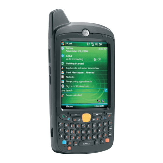
Motorola MC55 User Manual
Enterprise digital assistant
Hide thumbs
Also See for MC55:
- User manual (245 pages) ,
- Integrator manual (128 pages) ,
- Accessories manual (6 pages)
Table of Contents
Advertisement
Quick Links
Advertisement
Table of Contents
Troubleshooting

Related Manuals for Motorola MC55


Summary of Contents for Motorola MC55
- Page 1 MC55 Enterprise Digital Assistant User Guide...
- Page 3 MC55 Enterprise Digital Assistant User Guide 72E-108859-01 Rev. A December 2008...
-
Page 4: Patents
Motorola. No right to copy a licensed program in whole or in part is granted, except as permitted under copyright law. The user shall not modify, merge, or incorporate any form or portion of a licensed program with other program material, create a derivative work from a licensed program, or use a licensed program in a network without written permission from Motorola. -
Page 5: Revision History
Revision History Changes to the original manual are listed below: Change Date Description -01 Rev. A 12/15/08 Initial release. - Page 6 MC55 User Guide...
-
Page 7: Table Of Contents
Charging the Battery ........................1-5 Charging the Main Battery ....................... 1-5 Charging Spare Batteries ......................1-6 Charging Temperature ......................1-6 Powering On the MC55 ........................1-6 Calibrating the Screen ......................1-7 Checking Battery Status ........................ 1-7 Replacing the Battery .......................... 1-7 Removing the microSD Card ....................... - Page 8 MC55 User Guide Turning Off the Radios ........................1-9 Handstrap Replacement ........................1-12 Removal ............................1-12 Installation ............................1-13 Chapter 2: Using the MC55 Introduction ............................2-1 Today Screen ............................2-1 Status Icons ............................2-2 Programs ............................. 2-3 Settings ..............................2-5 Adjusting Volume ..........................
- Page 9 Table of Contents Turning the Bluetooth Radio Mode On and Off ................... 3-3 Disabling Bluetooth ........................3-3 Enabling Bluetooth ......................... 3-3 Bluetooth Power States ......................... 3-4 Cold Boot ..........................3-4 Warm Boot ..........................3-4 Suspend ........................... 3-4 Resume ............................ 3-4 Modes ..............................
- Page 10 MC55 User Guide Single Slot USB Cradle ........................4-2 Charging the MC55 Battery ......................4-2 Charging the Spare Battery ......................4-3 Battery Charging Indicators ......................4-3 Charging Temperature ......................4-3 Four Slot Charge Only Cradle ......................4-5 Charging ............................4-5 Battery Charging Indicators ......................
- Page 11 Table of Contents MC55 ............................. A-1 MC55 Accessory Specifications ......................A-6 Single Slot USB Cradle ........................A-6 Four Slot Battery Charger ......................A-6 Four Slot Charge Only Cradle ......................A-7 Cables ............................A-8 Appendix B: Voice Quality Manager Introduction ............................B-1 Features ...............................
- Page 12 MC55 User Guide...
-
Page 13: About This Guide
The documentation set for the MC55 provides information for specific user needs, and includes: • MC55 Quick Start Guide - describes how to get the MC55 EDA up and running. • MC55 User Guide - describes how to use the MC55 EDA. -
Page 14: Configurations
MC55 User Guide Configurations This guide covers the following configurations: Data Capture Operating Configuration Radios Display Memory Keypads Options System MC5590 WLAN: 802.11a/b/g 3.5” QVGA 128 MB RAM/ 1D laser Windows Numeric, WPAN: Bluetooth Color 256 MB Flash scanner, Mobile 6.1 Alphanumeric, v2.0 EDR... - Page 15 About This Guide xiii > > tab > icon > tab. Start Settings System System Information System BTExplorer Software To determine the BTExplorer software version: icon > > > BTExplorer Show BTExplorer Menu About BTExplorer icon Fusion Software To determine the Fusion software version: icon >...
-
Page 16: Chapter Descriptions
Topics covered in this guide are as follows: • Chapter 1, Getting Started provides information on getting the MC55 up and running for the first time. • Chapter 2, Using the MC55 provides basic instructions for using the MC55, including powering on and resetting the MC55, and entering and capturing data. -
Page 17: Related Documents
Software type and version number. Manufacturing label Motorola responds to calls by email, telephone or fax within the time limits set forth in support agreements. If your problem cannot be solved by Motorola Enterprise Mobility Support, you may need to return your equipment... - Page 18 MC55 User Guide shipment if the approved shipping container is not used. Shipping the units improperly can possibly void the warranty. If you purchased your Enterprise Mobility business product from a Motorola business partner, contact that business partner for support.
-
Page 19: Chapter 1 Getting Started
Chapter 1 Getting Started Introduction This chapter lists the parts and accessories for the MC55 and explains how to set up the MC55 for the first time. Radio Charging/Battery Scan/Decode Touch Screen with Status LED Status LED Protective Overlay Scan/Action... -
Page 20: Unpacking
Inspect the equipment for damage. If any equipment is missing or damaged, contact the Motorola Enterprise Mobility Support center immediately. See page xv for contact information. Prior to using the MC55 for the first time, remove the protective shipping film that covers the scan window, display and camera window. -
Page 21: Accessories
Four Slot Charge Only CRD5500-4000CR Charges up to four MC55 devices. Cradle Vehicle Holder VCH5500-1000R Mounts to a vehicle's windshield or dashboard and holds the MC55 while in a vehicle. Chargers Four Slot Spare Battery SAC5500-4000CR Charges up to four MC55 battery packs. -
Page 22: Installing A Microsd Card
• Charge the MC55. • Power on the MC55. Installing a microSD Card The microSD card slot provides secondary non-volatile storage. The slot is located under the battery pack. Refer to the documentation provided with the card for more information, and follow the manufacturer’s recommendations for use. -
Page 23: Installing The Battery
Battery Safety Guidelines on page 5-2. Charging the Main Battery Before using the MC55 for the first time, charge the main battery until the amber Charging/Battery Status LED remains lit (see Table 1-2 on page 1-6 for charge status indications). To charge the MC55, use a cable or a cradle with the appropriate power supply. -
Page 24: Charging Spare Batteries
Powering On the MC55 After inserting the battery or when turning the MC55 on for the first time, the splash screen displays for about a minute as the MC55 initializes its flash file system, then the calibration window appears. Note that these windows... -
Page 25: Calibrating The Screen
NOTE To check battery status, remove the MC55 from any AC power source (cradle, cables, etc.) To check the charge status of the main battery in the MC55, tap Start > Settings > System tab > Power icon to display the Power window. -
Page 26: Removing The Microsd Card
1 - 8 MC55 User Guide Removing the microSD Card To remove an microSD card: Press the red Power button to suspend the MC55. Remove the battery. Lift the rubber access door. Slide SIM card holder door to the left. -
Page 27: Battery Management
1 - 9 Battery Management Observe the following battery saving tips: • Leave the MC55 connected to AC power at all times when not in use. • Set the MC55 to turn off after a short period of non-use. •... - Page 28 1 - 10 MC55 User Guide To open Wireless Manager, tap the Connectivity icon or tap Wireless Manager on the Today screen. Connectivity icon Opening Wireless Manager Figure 1-7 Select Wireless Manager. Wireless Manager Window Figure 1-8 NOTE Wireless connection options vary depending upon configurations.
- Page 29 Getting Started 1 - 11 Wireless Manager Menu Figure 1-9...
-
Page 30: Handstrap Replacement
1 - 12 MC55 User Guide Handstrap Replacement Removal To remove a handstrap from the MC55: Pull up on the handstrap to remove the handstrap bracket from the end cap. Handstrap bracket Removal Figure 1-10 Remove the battery. Using a small flat screwdriver, push the head of the screwdriver between the handstrap pin and the bottom of the housing as shown below. -
Page 31: Installation
Figure 1-12 Pull handstrap through handstrap slot. Installation To install a new handstrap: Feed bottom end of handstrap into handstrap slot on the bottom of the MC55. Feed handstrap into Handstrap Slot Figure 1-13 Slide pin into bottom of handstrap. - Page 32 Slide Handstrap and Tether Over Handstrap Mount Figure 1-15 Slide tether loop over handstrap mount Align handstrap mount with mounting holes at the top of the MC55. Align Mount Bracket with Holes in End Cap Figure 1-16 Push the handstrap mount down until it snaps into position.
-
Page 33: Chapter 2 Using The Mc55
Chapter 2 Using the MC55 Introduction This chapter explains the buttons, status icons, and controls on the MC55, and provides basic instructions for using the MC55, including powering on and resetting the MC55, and entering and capturing data. Today Screen The Today screen displays important information, such as upcoming appointments and status indicators. -
Page 34: Status Icons
2 - 2 MC55 User Guide Status Icons The Navigation bar at the top of the screen can contain the status icons listed in Table 2-1. Status Icons Table 2-1 Icon Function Description Notification Notification that one or more instant messages were received. -
Page 35: Programs
Indicates the Bluetooth radio is off. Bluetooth Connection Indicates the Bluetooth radio is connected to another Bluetooth device. ActiveSync Indicates an active serial connection between the MC55 and the host computer. USB Client Mode Indicates that the MC55 is in USB Client mode. - Page 36 Synchronize information between the MC55 and a host computer or the Exchange Server. AirBEAM Allows specially designed software packages to be transferred between a host server and the MC55. Refer to the MC55 Integrator Guide for more information. BTExplorer Manages Bluetooth connections.
-
Page 37: Settings
Use this mobile version of Windows Live™ to find information on the web. Windows Media Play back audio and video files. Settings Table 2-5 lists control applications pre installed on the MC55. Tap Start > Settings to open the Settings window. Settings in the Setting Window Table 2-5 Icon Name Description... - Page 38 Set the appropriate GPS communication ports, if required. You may need to do this when there are programs on your device that access GPS data or you have connected a GPS receiver to the MC55. Keylight Set the keypad backlight time-out.
- Page 39 Make your device an AD domain member for device management and security. USB to PC Enables or disables the enhanced network connectivity. Wi-Fi Setup wireless network connection and customize settings. Wireless Manager Enables or disables the MC55’s wireless radios and customizes Wi-Fi and Bluetooth settings.
-
Page 40: Adjusting Volume
Select the On or Off radio button to turn the volume on or off. You can also adjust the system volume using the Sounds & Notifications window, or use the Up/Down button on the side of the MC55. Battery Status Indications Battery icons appear on the navigation bar indicating the battery power level. -
Page 41: Battery Reserve Options
Figure 2-5 Battery Reserve Options If the charge of the battery reaches a critical threshold, the MC55 shuts down. This threshold can be changed but affects the amount of time that data can be retained. Tap Start > Settings > System tab > Power icon > RunTime tab. A warning message appears. -
Page 42: Main Battery Temperature Notifications
• Level 3: Temperature Error; this level indicates the battery has reached an unusable temperature threshold and immediately suspends the MC55. This level does not have any graphical notification associated with it. Main Battery Temperature Watch Dialog Box Figure 2-8... -
Page 43: Led Indicators
Hide NOTE The dialog box remains visible until you tap LED Indicators The MC55 has two LED indicators. The Scan/Decode LED indicates status for scanning. The Charging/Battery Status LED indicates battery charging and status. Table 2-6 describes the LED indications. -
Page 44: Resetting The Mc55
A cold boot also restarts the MC55, and also resets the clock. Data saved in flash memory or a memory card is not lost. If the MC55 is not functioning properly, perform a warm boot first. If the MC55 still does not respond, perform a cold boot. -
Page 45: Locking The Mc55
You can lock the MC55 by disabling key presses and screen tap or by requiring a password. Keypad Locking Locking the MC55 turns off keyboard and touch screen functionality. This is helpful when the MC55 is turned on and you want to prevent accidental key presses. -
Page 46: Password Locking
Unlock Device Window Figure 2-12 Tap Unlock on the Unlock window. NOTE You can make emergency calls even when the MC55 is locked. See Making an Emergency Call on page 5-6 for more information. Password Locking Use the Password window to set a password to disable unauthorized access to the MC55. - Page 47 Figure 2-14 In the text box, enter a hint for a password reminder. Tap ok. When the MC55 is not used for a period of time and the user tries to access the device, the Password window appears. Enter Password Windows Figure 2-15 Enter the password to un-lock the device.
-
Page 48: Keypads
2 - 16 MC55 User Guide Keypads The MC55 offers two types modular keypad configurations: Numeric and alpha-numeric. Numeric Keypad Configuration The numeric keypad contains application keys, scroll keys, and function keys. The keypad is color-coded to indicate the alternate function key (blue) values. Note that an application can change keypad functions so the MC55’s keypad may not function exactly as described. - Page 49 [where xx is the new APP key code] Provision the file to the MC55 to send an APP key code, instead of the original key code, upon pressing the green phone key. Refer to the MC55 Integrator Guide for information on creating XML provisioning files.
- Page 50 2 - 18 MC55 User Guide MC55 Numeric Keypad Descriptions (Continued) Table 2-8 Description Star Produces an asterisk in default state. Press and release the blue key, then press the Star key to open the Start menu. Alphanumeric In default state, produces the numeric value on the key.
-
Page 51: Alpha-Numeric Keypad Configurations
Using the MC55 2 - 19 Numeric Keypad Input Modes (Continued) Table 2-9 Orange Key Orange + Shift Keys Numeric Mode (Alpha Lowercase Mode) (Alpha Uppercase Mode) Blue+ SHIFT + Key Press Press Press Press Press Press Press Press &... - Page 52 2 - 20 MC55 User Guide AZERTY Keypad Configuration Figure 2-18 QWERTZ Keypad Configuration Figure 2-19...
- Page 53 [where xx is the new APP key code] Provision the file to the MC55 to send an APP key code, instead of the original key code, upon pressing the green phone key. Refer to the MC55 Integrator Guide for information on creating XML provisioning files.
- Page 54 [where yy is the new APP key code] Provision the file to the MC55 to send an APP key code, instead of the original key code, upon pressing the red phone key. Refer to the MC55 Integrator Guide for information on creating XML provisioning files.
- Page 55 Using the MC55 2 - 23 Alpha-numeric Keypad Descriptions (Continued) Table 2-10 Action Enter Executes a selected item or function. Star Produces an asterisk. Creates special characters. QWERTY Keypad Input Modes Table 2-11 Normal Shift + Key Orange + Key Blue + Key “...
- Page 56 2 - 24 MC55 User Guide QWERTY Keypad Input Modes (Continued) Table 2-11 Normal Shift + Key Orange + Key Blue + Key ‘ Backspace Backspace Backspace Backspace Backspace Shift Shift Shift-Lock Shift Shift & < ENTER Enter Enter Enter Enter >...
- Page 57 Using the MC55 2 - 25 AZERTY Keypad Input Modes (Continued) Table 2-12 Normal Shift + Key Orange + Key Blue + Key áü ‘ Backspace Backspace Backspace Backspace Backspace Shift Shift Shift-Lock Shift Shift & < Enter Enter Enter...
- Page 58 2 - 26 MC55 User Guide QWERTZ Keypad Input Modes Table 2-13 Normal Shift + Key Orange + Key Blue + Key “ áü ‘ Backspace Backspace Shift Shift & < Note: An application can change the key functions. The keypad may not function exactly as described.
-
Page 59: Special Character Key
NOTE Special characters are only available on the alpha-numeric keypad configurations. To add special characters using the MC55 áü key, type the related character first, then press the Orange twice followed by the áü (P) key. Continue pressing the áü key until the special character displays. To modify an existing character, move the cursor to the right of the character then press the Orange key twice and then press the áü... - Page 60 2 - 28 MC55 User Guide Special Characters (Continued) Table 2-14 Special Characters Special Characters “ & ‘...
-
Page 61: Function Buttons
Function Buttons Figure 2-20 • Power: Press the red Power button to turn the MC55 screen on and off. The MC55 is in suspend mode when the screen is off. For more information, see Powering On the MC55 on page 1-6. -
Page 62: Entering Data
2 - 30 MC55 User Guide Entering Data When entering data on the keypad, use either the single-hand method or the two-hand method as shown in Figure 2-21. Two-hand Method Single-hand Method Entering Data on the Keypad Figure 2-21... -
Page 63: Data Capture
(either 1D or 2D). • Image Capture Mode: Use this mode to capture an image within the MC55’s field of view. This is useful for capturing signatures or images of items like damaged boxes. -
Page 64: Digital Camera
Hold the MC55 farther away for larger symbols. • Move the MC55 closer for symbols with bars that are close together. NOTE Scanning procedures depend on the application and MC55 configuration. An application may use different scanning procedures from the one listed above. Linear Scanning Ensure that a scan enabled application is loaded on the MC55. -
Page 65: Imager Scanning
Note that when the MC55 is in Pick List Mode, the imager does not decode the bar code until the... -
Page 66: Digital Camera Scanning
Figure 2-27 Release the scan button. NOTE Imager decoding usually occurs instantaneously. The MC55 repeats the steps required to take a digital picture (image) of a poor or difficult bar code as long as the scan button remains pressed. Digital Camera Scanning Ensure that a scan-enabled application is loaded on the MC55. -
Page 67: Using Voice-Over-Ip
Using Voice-Over-IP The MC55 supports Voice over IP over WLAN (VoWLAN) using Motorola or third party voice clients. The MC55 can communicate using VoIP either using the MC55 audio outputs, including back speaker phone, front receiver or handset, and Bluetooth headset. -
Page 68: Recording Video
2 - 36 MC55 User Guide Recording Video To record a video clip: Tap Start > Programs > Pictures & Videos icon. Tap Camera on the command bar. Tap Menu > Video to set shooting mode to video. The available recording time displays on the screen. -
Page 69: Chapter 3 Using Bluetooth
MC55s with Bluetooth capabilities can exchange information (e.g., files, appointments, and tasks) with other Bluetooth enabled devices such as phones, printers, access points, and other mobile computers. To use the MC55 as a modem, create a dial-up modem connection between a computer and MC55. -
Page 70: Security
MC55 User Guide The Bluetooth radio in this MC55 operates as a Class 2 device power class. The maximum output power is 2.5mW and the expected range is 32.8 feet (10 meters). A definition of ranges based on power class is difficult to obtain due to power and device differences, and whether one measures open space or closed office space. -
Page 71: Turning The Bluetooth Radio Mode On And Off
Turn off the Bluetooth radio to save power or if entering an area with radio restrictions (e.g., an airplane). When the radio is off, other Bluetooth devices cannot see or connect to the MC55. Turn on the Bluetooth radio to exchange information with other Bluetooth devices (within range). -
Page 72: Bluetooth Power States
Cold Boot Performing a cold boot on the MC55 turns off Bluetooth after initialization (which takes a few moments). It is normal to see the Bluetooth icon appear and disappear, as well as a wait cursor, when initialization proceeds in all modes. - Page 73 Using Bluetooth 3 - 5 Explorer Mode Window Figure 3-3 You can also use the “tap and hold” technique to view available options. Scroll bars and view options are similar to those on the Windows desktop. The tree structure lists the following sub-items: •...
-
Page 74: Discovering Bluetooth Device(S)
3 - 6 MC55 User Guide Discovering Bluetooth Device(s) The MC55 can receive information from discovered devices without bonding. However, once bonded, the MC55 and a bonded device exchange information automatically when you turn the Bluetooth radio on. See Bonding with Discovered Device(s) on page 3-18 for more information. - Page 75 Discover Devices Dialog Box Figure 3-5 The discovered devices display in the Select Remote Device window. Select Remote Device Window Figure 3-6 Select a device from the list and tap Next. The MC55 searches for services on the selected Bluetooth device.
- Page 76 Device Services Figure 3-7 NOTE If the MC55 discovers a service but the service is not supported, the service icon is grayed-out. Select a service from the list and press Next. The Connection Favorite Options window appears. Connection Favorite Options Window Figure 3-8 In the Favorite Name text box, enter a name for this service that will appear in the Favorite window.
-
Page 77: Available Services
To transfer files between the MC55 and another Bluetooth enabled device: Ensure the MC55 is discoverable and connectable. See Device Info Tab on page 3-20. Ensure that OBEX File Transfer profile is enabled on the MC55. See Profiles Tab on page 3-28 for more information. -
Page 78: Creating A New File Or Folder
• Delete - delete the selected file on the remote device. • Get File - copy the file from the remote device to the MC55. • Put File - copy a file from the MC55 to the remote device. Creating a New File or Folder To create a new folder or file on the remote device: Tap and hold on the screen and select New >... -
Page 79: Deleting A File
Double-tap or tap and hold on the file and select Get. The Save Remote File window appears. Navigate to the directory to save the file. Tap Save. The file is transferred from the remote device to the MC55. Copying a File To copy a file to a remote device: Tap Action >... -
Page 80: Sending A Contact
To exchange contact information with another Bluetooth enabled device: Ensure the MC55 is discoverable and connectable. See Device Info Tab on page 3-20. Ensure that the OBEX Object Push profile is enabled on the MC55. See Profiles Tab on page 3-28 for more information. -
Page 81: Swapping Contacts
Using Bluetooth 3 - 13 Select Contact Entry Window Figure 3-13 Select a contact to send to the other device. Tap OK. Tap OK to send the contact to the other device and display a confirmation dialog box on the other device to accept the contact. -
Page 82: Fetching A Contact
3 - 14 MC55 User Guide Select Contact Entry Window Figure 3-15 Select a contact to send to the other device. Tap OK. Tap OK to swap contacts with the other device and display a confirmation dialog box on the other device to accept the contact. -
Page 83: Headset Services
NOTE Newer Bluetooth headsets are device dependant and remember the last device they connected to. If problems occur while connecting to the headset, place the headset in discovery mode. Refer to the headset user manual for more information. Ensure the MC55 is discoverable and connectable. See Device Info Tab on page 3-20. -
Page 84: Serial Port Services
Use the Connection Wizard to search for a Bluetooth headset. Select the device and tap Next. Select the Headset service name and select Connect. The MC55 connects to the headset. Refer to the headset user manual for instructions on communicating with a Bluetooth device. - Page 85 Figure 3-20 In the Service Type drop-down list, select Active Sync. Tap OK. The MC55 connects the PC and an ActiveSync session begins. Tap Finish. The Connection Favorite Options window appears. To end the session, tap the ActiveSync icon in the Favorite window and select Disconnect from the pop-up...
-
Page 86: Personal Area Network Services
Bonding with Discovered Device(s) A bond is a relationship created between the MC55 and another Bluetooth device in order to exchange information in a secure manner. Creating a bond involves entering the same PIN on the two devices. After creating a bond and turning on the Bluetooth radios, the devices recognize the bond and can exchange information without re-entering a PIN. - Page 87 Using Bluetooth 3 - 19 Select Remote Device Window Figure 3-21 Select a device from the list and tap Next. The PIN Code Request window appears. Connection Favorite Options Window Figure 3-22 In the PIN Code field, enter the PIN code. Tap OK.
-
Page 88: Deleting A Bonded Device
A confirmation dialog appears. Tap Yes. Accepting a Bond When a remote device wants to bond with the MC55, enter a PIN when requested to grant permission. Ensure that the MC55 is set to discoverable and connectable. See Bluetooth Settings on page 3-20. -
Page 89: Services Tab
Description Device Name Displays the name of the MC55. Discoverable Mode Select whether or not the MC55 is discoverable by other Bluetooth devices. Connectable Mode Select whether or not the MC55 is connectable by other Bluetooth devices. Services Tab Use the Services tab to add or delete Bluetooth services. -
Page 90: File Transfer Service
3 - 22 MC55 User Guide Add Local Service Window Figure 3-27 In the list, select a service to add. Tap OK. The Edit Local Service window displays for the selected service. Select the appropriate information and then tap OK. See the following sections for information on the available services. -
Page 91: Headset Audio Gateway Service
Lists the name of the audio service. OBEX Object Push Service OBEX Object Push allows other Bluetooth devices to push contacts, business cards, pictures, appointments, and tasks to the MC55. BTExplorer Settings - OBEX Exchange Information Figure 3-30 OBEX Exchange Information Data... -
Page 92: Personal Area Networking Service
Select the type of security from the drop-down list. Options are None, Authenticate, or Authenticate/Encrypt. Do not allow clients to push objects Disables clients from pushing objects to the MC55. Inbox Directory Select a directory where another Bluetooth device can store files. -
Page 93: Security Tab
Using Bluetooth 3 - 25 BTExplorer Settings - Serial Port Services Figure 3-32 Serial Port Services Data Table 3-6 Item Description Service Name Displays the name of the service. Service Security Select the type of security from the drop-down list. Options are None, Authenticate, or Authenticate/Encrypt. -
Page 94: Discovery Tab
3 - 26 MC55 User Guide BTExplorer Settings - Security Tab Figure 3-33 Authenticate Authenticate/Encrypt NOTE To use PIN Code, select from the Service Security drop-down list on each local service. Security Tab Data Table 3-7 Item Description Use PIN Code (Incoming Select for automatic use of the PIN code entered in the PIN Code text box. -
Page 95: Virtual Com Port Tab
Table 3-8 Item Description Inquiry Length Sets the amount of time the MC55 takes to discover Bluetooth devices in the area. Name Discovery Mode Select either Automatic or Manual to automatically attempt to discover a Bluetooth device's name after finding the device. -
Page 96: Hid Tab
3 - 28 MC55 User Guide HID Tab Use the HID tab to select The Human Interface Device Profile programming interface defines the protocols and procedures to be used to implement HID capabilities. Provides support for devices such as mice, joysticks, keyboards. -
Page 97: System Parameters Tab
Link Supervision Timeout Sets the amount of time that the MC55 will wait for a device to come back into range after it has gone out of range. If the device does not come back into range by the set time, the MC55 drops the connection. - Page 98 3 - 30 MC55 User Guide Miscellaneous tab Data Table 3-12 Item Description Highlight Connections Select the connection type to highlight when connected. In the Wizard Mode, the only options are Favorites or None. In the Explorer Mode the options are None, Tree View Only, List View Only, or Tree and List View.
-
Page 99: Chapter 4 Accessories
• Four Slot Charge Only Cradle - Charges up to four MC55 devices. • Single Slot USB Cradle - Charges the MC55 main battery and a spare battery. Synchronizes the MC55 with a host computer through a USB connection. •... -
Page 100: Single Slot Usb Cradle
4 - 2 MC55 User Guide Single Slot USB Cradle This section describes how to use a Single Slot USB cradle with the MC55. For USB communication setup procedures refer to the MC55 Integrator Guide. The Single Slot USB Cradle: •... -
Page 101: Charging The Spare Battery
Figure 4-2 Battery Charging Indicators The Single Slot USB Cradle charges the MC55’s main battery and a spare battery simultaneously. The MC55’s charge LED indicates the status of the battery charging in the MC55. See Table 1-2 on page 1-6 charging status indications. - Page 102 4 - 4 MC55 User Guide To accomplish this, for small periods of time, the MC55 or accessory alternately enables and disables battery charging to keep the battery at acceptable temperatures. The MC55 or accessory indicates when charging is disabled due to abnormal temperatures via its LED. See...
-
Page 103: Four Slot Charge Only Cradle
Accessories 4 - 5 Four Slot Charge Only Cradle This section describes how to set up and use a Four Slot Charge Only cradle with the MC55. The Four Slot Charge Only cradle: • Provides 5.4 VDC power for operating the MC55. -
Page 104: Four Slot Battery Charger
4 - 6 MC55 User Guide Four Slot Battery Charger This section describes how to use the Four Slot Battery Charger to charge up to four MC55 batteries. Battery Charging Connect the charger to a power source. Insert the battery into a battery charging well and gently press down on the battery to ensure proper contact. - Page 105 Accessories 4 - 7 Battery LED Charging Indicators (Continued) Table 4-2 Indication Slow Blinking Amber Battery is charging. Solid Amber Charging complete. Fast Blinking Amber Charging error.
-
Page 106: Cables
To charge the MC55 battery: Connect the communication/charge cable power input connector to the Motorola approved power source. Slide the bottom of the MC55 into the connector cup end of the communication/charge cable and gently press in until it latches into the MC55. -
Page 107: Led Charge Indications
1-2 on page 1-6 for charging status indications. When charging is complete, push the two locking tab down and remove the cable from the MC55. LED Charge Indications The amber Charge LED on the MC55 indicates battery charging status. See... -
Page 108: Charging Temperature
Charge batteries in temperatures from 0°C to 40°C (32°F to 104°F). Charging is intelligently controlled by the MC55. To accomplish this, for small periods of time, the MC55 or accessory alternately enables and disables battery charging to keep the battery at acceptable temperatures. The MC55 or accessory indicates when charging is disabled due to abnormal temperatures via its LED. -
Page 109: Vehicle Holder
Do not mount the vehicle holder near the driver seat air bag deployment area. • Do not place the MC55 on top of the dashboard or anywhere without securing it in the vehicle holder. • Do not mount the vehicle holder near the passenger seat air bag deployment area. -
Page 110: Assembly
4 - 12 MC55 User Guide Assembly Insert the vehicle holder’s cradle plate to the holes on the back of the cradle. Push the cradle down until both parts are engaged. Windshield Installation Fix the suction cup mount to the selected area with the suction lever facing up. -
Page 111: Flat Surface Installation
Locking Tab Insert MC55 into Vehicle Holder Figure 4-8 Connect the auto charger cable to the MC55 and slide the two locking tabs up to secure the cable cup to the MC55. Connect the other end to the cigarette lighter socket. - Page 112 Vehicle Holder Mounted on Flat Surface Figure 4-10 Connect the auto charger cable to the MC55 and slide the two locking tabs up to secure the cable cup to the MC55. Connect the other end to the cigarette lighter socket.
-
Page 113: Chapter 5 Maintenance & Troubleshooting
Do not store or use the MC55 in any location that is dusty, damp, or wet. • Use a soft lens cloth to clean the MC55. If the surface of the MC55 screen becomes soiled, clean it with a soft cloth moistened with a diluted window-cleaning solution. -
Page 114: Removing The Screen Protector
• Quick and easy installation. Removing the Screen Protector A screen protector is applied to the MC55. Motorola recommends using this to minimize wear and tear. Screen protectors enhance the usability and durability of touch screen displays. To remove the screen protector, lift the corner using a thin plastic card, such as a credit card, then carefully lift it off the display. -
Page 115: Cleaning
Read warning label on compressed air and alcohol product before using. If you have to use any other solution for medical reasons please contact Motorola for more information. Avoid exposing this product to contact with hot oil or other flammable liquids. If such exposure WARNING occurs, unplug the device and clean the product immediately in accordance with these guidelines. -
Page 116: Cleaning The Mc55
Dip the cotton portion of the cotton tipped applicator in isopropyl alcohol. Rub the cotton portion of the cotton tipped applicator back-and-forth across the connector on the bottom of the MC55. Do not leave any cotton residue on the connector. Repeat at least three times. -
Page 117: Cleaning Frequency
Install the battery properly. See Installing the Battery on page 1-5. not installed properly. System crash. Perform a warm boot. If the MC55 still does not turn on, perform a cold boot. See Resetting the MC55 on page 2-12. Rechargeable Battery failed. - Page 118 MC55 shuts off. MC55 is inactive. The MC55 turns off after a period of inactivity. If the MC55 is running on battery power, set this period from 1 to 5 minutes, in one-minute intervals. If the MC55 is running on external power, set this period to 1, 2, 5, 10, 15, or 30 minutes.
-
Page 119: Bluetooth Connection
Refer to the EMDK or Control Panel application. bar code. MC55 is not If the MC55 does not beep on a good decode, set the application programmed to to generate a beep on good decode. generate a beep. -
Page 120: Single Slot Usb Cradle
AC power. battery is inserted. MC55 is not seated Remove and re-insert the MC55 into the cradle, ensuring it is firmly firmly in the cradle. seated. Spare battery is not Remove and re-insert the spare battery into the charging slot, seated firmly in the ensuring it is firmly seated. -
Page 121: Four Slot Battery Charger
Battery is faulty. Verify that other batteries charge properly. If so, replace the faulty battery. The MC55 is not Detach and re-attach the power cable to the MC55, ensuring it is fully attached to firmly connected. power. During data Cable was Re-attach the cable and retransmit. - Page 122 5 - 10 MC55 User Guide...
-
Page 123: Appendix A Technical Specifications
Appendix A Technical Specifications MC55 Technical Specifications The following tables summarize the EDA’s intended operating environment and technical hardware specifications. MC55 MC55 EDA Technical Specifications Table A-1 Item Description Physical Characteristics Dimensions Height: 14.7 cm (5.78 in.) Width: 7.7 cm (3.03 in.) Depth: 2.7 cm (1.06 in.) - Page 124 A - 2 MC55 User Guide MC55 EDA Technical Specifications (Continued) Table A-1 Item Description Keypad Options 26 key numeric 44 key QWERTY, 44 key AZERTY, 44 key QWERTZ Audio Speaker, receiver, microphone, software support for full duplexcapability, Bluetooth stereo.
- Page 125 Technical Specifications A - 3 MC55 EDA Technical Specifications (Continued) Table A-1 Item Description Antenna Internal for WLAN Voice Communication Voice-over-IP ready (with P2P, PBX, PTT clients), Wi-Fi™-certified, IEEE 802.11 a/b/g direct sequence wireless LAN Wireless PAN Data and Voice Communications Bluetooth Class II, v 2.0 EDR;...
- Page 126 A - 4 MC55 User Guide MC55 EDA Technical Specifications (Continued) Table A-1 Item Description Aiming Element (VLD) 650 nm +/- 5 nm Illumination Element (LED) 635 nm +/- 20 nm Camera Specifications Resolution 2 Mega pixel with flash and auto focus.
- Page 127 Technical Specifications A - 5 Data Capture Options (Continued) Table A-2 Item Description Imaging Decode Capability Code 39 Code 128 Code 93 Codabar Code 11 Interleaved 2 of 5 Discrete 2 of 5 EAN-8 EAN-13 UPCA UPCE UPC/EAN supplementals Coupon Code Trioptic 39 Webcode TLC39...
-
Page 128: Mc55 Accessory Specifications
A - 6 MC55 User Guide MC55 Accessory Specifications Single Slot USB Cradle Single Slot USB Cradle Technical Specifications Table A-3 Feature Description Dimensions Height: 7.1 cm (2.80 in.) Width: 11.0 cm (4.33 in.) Depth: 15.0 cm (5.91 in.) Weight 210 g (7.41 oz) -
Page 129: Four Slot Charge Only Cradle
Technical Specifications A - 7 Four Slot Battery Charger Technical Specifications (Continued) Table A-4 Feature Description Humidity 5% to 95% non-condensing Drop 76.2 cm (30.0 in.) drops to vinyl tiled concrete at room temperature Electrostatic Discharge (ESD) +/- 15 kV air +/- 8 kV contact Four Slot Charge Only Cradle Four Slot Charge Only Cradle Technical Specifications... -
Page 130: Cables
A - 8 MC55 User Guide Cables USB Charging Cable Technical Specifications Table A-6 Feature Description Length 161.9 cm (63.74 in.) Operating Temperature -10°C to 50°C (14°F to 122°F) Storage Temperature -40°C to 70°C (-40°F to 158°F) Humidity 10% to 95% non-condensing... -
Page 131: Appendix B Voice Quality Manager
Introduction The Voice Quality Manager (VQM) is a software package that resides on the MC55. VQM enables a set of features for Voice over WLAN (VoWLAN) calls. The VQM user interface is designed to be intuitive and easy to use, so complex tasks such as enabling the Acoustic Echo Canceller (AEC) while a call is in progress are done with very little or no user intervention. -
Page 132: Audio Modes
B - 2 MC55 User Guide Audio Modes The MC55 can be in any one of the seven different audio modes. The mode is visually indicated by the VQM icon on the title bar. VQM icon VQM Icon in Title Bar... -
Page 133: Voice Packet Prioritization
Voice Quality Manager B - 3 If the user is using a Bluetooth headset, tapping the VQM icon un-pairs the Bluetooth headset from the device causing the audio to be routed to the default mode. In VQM 2.5, there is no way to go back to the Bluetooth headset using the VQM icon if it is un-paired The only way to reconnect the Bluetooth headset to the device is by using the BTExplorer application. -
Page 134: Limitations
B - 4 MC55 User Guide Limitations • There is no VPN support in VQM. • Only the Avaya softphone is currently supported. Acoustic Echo Cancellation Acoustic Echo occurs during a voice call when the audio from the earpiece enters the microphone of the same device. -
Page 135: Glossary
Glossary API. (Application Programming Interface) An interface by means of which one software component communicates with or controls another. Usually used to refer to services provided by one software component to another, usually via software interrupts or function calls AZERTY. A standard keyboard commonly used on French keyboards. “AZERTY” refers to the arrangement of keys on the top row of keys. - Page 136 Glossary - 2 MC55 User Guide bps. See Bits Per Second. Byte. On an addressable boundary, eight adjacent binary digits (0 and 1) combined in a pattern to represent a specific character or numeric value. Bits are numbered from the right, 0 through 7, with bit 0 the low-order bit. One byte in memory is used to store one ASCII character.
- Page 137 Glossary - 3 Decode Algorithm. A decoding scheme that converts pulse widths into data representation of the letters or numbers encoded within a bar code symbol. Decryption. Decryption is the decoding and unscrambling of received encrypted data. Also see, Encryption and Key. Depth of Field.
- Page 138 IEEE Address. See MAC Address. Input/Output Ports. I/O ports are primarily dedicated to passing information into or out of the terminal’s memory. MC55 mobile computers include USB ports. Interleaved 2 of 5. A binary bar code symbology representing character pairs in groups of five bars and five interleaved spaces.
- Page 139 Mobile Computer. In this text, mobile computer refers to the MC55. It can be set up to run as a stand-alone device, or it can be set up to communicate with a network, using wireless radio technology.
- Page 140 Glossary - 6 MC55 User Guide Open System Authentication. Open System authentication is a null authentication algorithm. PAN . Personal Area Network. Using Bluetooth wireless technology, PANs enable devices to communicate wirelessly. Generally, a wireless PAN consists of a dynamic group of less than 255 devices that communicate within about a 33-foot range.
- Page 141 Glossary - 7 Soft Reset. See Warm Boot. Space. The lighter element of a bar code formed by the background between bars. Specular Reflection. The mirror-like direct reflection of light from a surface, which can cause difficulty decoding a bar code. Start/Stop Character.
- Page 142 Glossary - 8 MC55 User Guide TFTP. (Trivial File Transfer Protocol) A version of the TCP/IP FTP (File Transfer Protocol) protocol that has no directory or password capability. It is the protocol used for upgrading firmware, downloading software and remote booting of diskless devices.
- Page 143 Index Numerics key descriptions ......2-21 Auto Charge Cable ......4-1 1-D bar codes .
- Page 144 Index - 2 MC55 User Guide Bluetooth ......3-18 image capture mode ....2-31 boot pick list mode .
- Page 145 Index - 3 key descriptions QWERTY keypad alpha-numeric keypad ....2-21 input modes ....2-23, 2-24, 2-26 numeric keypad .
- Page 146 Index - 4 MC55 User Guide stylus ......1-2, 1-3, 2-29 suspend ......1-7, 2-29, 3-4 task tray icons .
- Page 148 1-800-927-9626 http://www.motorola.com/enterprisemobility MOTOROLA and the Stylized M Logo and Symbol and the Symbol logo are registered in the U.S. Patent and Trademark Office. All other product or service names are the property of their registered owners. © Motorola, Inc. 2008...
Need help?
Do you have a question about the MC55 and is the answer not in the manual?
Questions and answers