Table of Contents
Advertisement
Quick Links
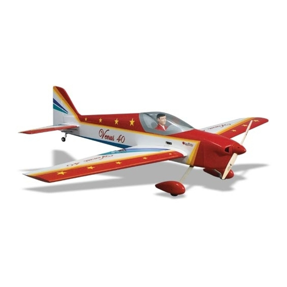
Wingspan: 55 in [1400mm]
Wing Area: 568 sq in [36.6 dm
Weight: 4.8 to 5.3 lbs [2180 to 2410g]
Wing Loading: 19.5 to 21.5 oz/sq ft [59 to 66 g/dm
Length: 54 in [1370mm]
Radio: 4-Channel (5 servos)
Engine: .40 - .51 cu in [6.5 - 8.5cc] two-stroke, .52 – .70 cu in
[8.5 - 11.5cc] four-stroke
Great Planes
®
Model Manufacturing Co. guarantees this kit to be free from defects in both material and workmanship at the date of purchase.
This warranty does not cover any component parts damaged by use or modification. In no case shall Great Planes' liability exceed the
original cost of the purchased kit. Further, Great Planes reserves the right to change or modify this warranty without notice.
In that Great Planes has no control over the final assembly or material used for final assembly, no liability shall be assumed nor accepted for
any damage resulting from the use by the user of the final user-assembled product. By the act of using the user-assembled product, the user
accepts all resulting liability.
If the buyer is not prepared to accept the liability associated with the use of this product, the buyer is advised to return this kit
immediately in new and unused condition to the place of purchase.
READ THROUGH THIS MANUAL BEFORE STARTING
CONSTRUCTION. IT CONTAINS IMPORTANT INSTRUCTIONS
AND WARNINGS CONCERNING THE ASSEMBLY AND
USE OF THIS MODEL.
GPMZ0238 for GPMA1025 V1.1
INSTRUCTION MANUAL
2
]
2
]
™
WARRANTY
1610 Interstate Drive Champaign, IL 61822
(217) 398-8970, Ext. 2
airsupport@greatplanes.com
Entire Contents © Copyright 2002
Advertisement
Table of Contents

Related Manuals for GREAT PLANES Venus 40arf


Summary of Contents for GREAT PLANES Venus 40arf
-
Page 1: Instruction Manual
Further, Great Planes reserves the right to change or modify this warranty without notice. In that Great Planes has no control over the final assembly or material used for final assembly, no liability shall be assumed nor accepted for any damage resulting from the use by the user of the final user-assembled product. -
Page 2: Table Of Contents
Great Planes Venus 40 ARF visit the web site listed below Optional Supplies & Tools ..........3 and select the Great Planes Venus 40 ARF. If there is new IMPORTANT BUILDING NOTES ........4 technical information or changes to this model a “tech ORDERING REPLACEMENT PARTS ......5... -
Page 3: Additional Items Required
Hardware & Accessories Here is a list of optional tools mentioned in the manual that will help you build the Great Planes Venus 40 ARF. This is the list of hardware and accessories required to finish the Venus 40 ARF. Order numbers are provided in Easy Fueler ™... -
Page 4: Important Building Notes
Frequently you can study photos in following steps 6-Minute epoxy (GPMR6045) to get another view of the same parts. Epoxy brushes (GPMR8060) Mixing sticks (GPMR8055) • The Great Planes Venus 40 ARF is factory-covered with Denatured alcohol (for epoxy clean up) Top Flite ® MonoKote ®... -
Page 5: Ordering Replacement Parts
ORDERING REPLACEMENT PARTS To order replacement parts for the Great Planes Venus 40 ARF, use the order numbers in the Replacement Parts List that follows. Replacement parts are available only as listed. Not all parts are available separately (an aileron cannot be purchased separately, but is only available with the wing kit). -
Page 6: Kit Contents
KIT CONTENTS Kit Contents (Photographed) Stab CA Hinge Material 17 Fiberglass Cowl Elevators 10 Engine Mount 18 Fuel Tank Fuselage & Belly Pan 11 Dihedral Brace 19 Wheel Pants Canopy 12 Hardware Bag 20 Foam Wheels 13 Wing Bolt Plate 21 Aluminum Landing Gear Rudder 14 Wing Dowels... -
Page 7: Preparations
PREPARATIONS 1. If you have not done so already, remove the major parts of the kit from the box (wings, fuselage, cowl, tail parts, etc.) and inspect them for damage. If any parts are damaged or missing, contact Product Support at the address or telephone number listed in the front cover. - Page 8 8. Feel through the MonoKote on the bottom surface of the wing and find the opening for the aileron servo. Cut the covering 1/8" [3.2mm] inside the opening. Use a sealing iron or trim seal tool to seal the covering to the edges of the opening.
-
Page 9: Join The Wing
dihedral angle on the wing joiner is pointing towards the bottom of the wing. You may need to sand the joiner slightly to obtain a perfect fit. 2. The following are critical steps in the construction of your model. You want to make sure you take as much time as necessary to glue the two wings together correctly. -
Page 10: Mount The Wing On The Fuselage
MonoKote on the top and bottom of the wing and seal with a sealing iron. 3. Test fit the wing to the fuse and bolt it in position using two 1/4-20 x 2" [51mm] nylon bolts. If necessary, enlarge or adjust the wing bolt holes in the wing so the wing bolts will align with the blind nuts. - Page 11 Tip that follows to cut the covering from the wing. Use care to cut only into the covering and not into the wood. 8. Flip the wing over. Use a 1/4" [6.4mm] drill bit through the pre-drilled wing bolt holes to drill through the wing bolt HOW TO CUT COVERING FROM BALSA plate as shown.
-
Page 12: Assemble The Fuselage
11. Use a hobby knife with a sharp #11 blade to trim the covering on the belly pan 1/16" [1.6mm] away from the 2. Fit the stab into the fuse. Center the trailing edge by edge. Seal the MonoKote down with a sealing iron. taking accurate measurements as shown in “X”=“X”... - Page 13 use a trim iron to iron the covering to the stab before the epoxy hardens. Do not disturb the model until the epoxy has fully hardened. 5. Fold a piece of masking tape over the end of the string and draw an arrow on it. Slide the tape along the string and align the arrow with one corner of the stab as shown in the photo.
- Page 14 13. Use a Groove Tube or a sharpened 3/32" [2.4mm] brass tube to cut a groove on the leading edge of the rudder to accommodate the tail wheel wire. 11. Position the tail wheel assembly in place and mark 14. Cut six CA hinges for the elevators and three for the the location of the two mounting holes.
-
Page 15: Engine Installation
It would be a good idea to use some Great Planes Pro Thread Locking Compound on the engine mount bolts. 1. Cut the engine mount template from the back cover page. -
Page 16: Radio Installation
Install the engine (less muffler) and connect the fuel carburetor line to the carburetor or remote needle valve. Use a Great Planes Aluminum Fuel Line Plug to plug the fill fuel line. If you wish, you could install a Great Planes Easy Fueler ™... - Page 17 Place the two wheel collars as horns with six 2-56 x 5/8" [16mm] bolts and the control horn shown, put a drop of Great Planes Pro Thread Locking back plates. Compound in the wheel collar screw hole and tighten the...
-
Page 18: Installing The Cowl
Installing the Cowl full range of carburetor rotation with the servo rotation. Use some Great Planes Pro Thread Locking Compound on the SHCS to prevent it from coming loose with vibration. 1. Draw a line 1/2" [12mm] away from the firewall, parallel to the firewall. - Page 19 valve. Install the engine’s muffler. Use paper strips to mark the location of the needle valve, engine glow plug access and muffler. Remove the muffler and needle valve. 3. Draw a line on the cowl using a Top Flite Panel Line Pen 1/4"...
-
Page 20: Installing The Landing Gear
Use Install the Landing Gear some Great Planes Pro Thread Locking Compound on the nuts to prevent them from loosening with vibration. Make sure you center the wheel within the wheel pant opening. -
Page 21: Get The Model Ready To Fly
If, after you have become accustomed to the way diagram. If any of the controls respond in the wrong the Great Planes Venus 40 ARF flies, you would like to direction, use the servo reversing in the transmitter to change the throws to suit your taste, that is fine. -
Page 22: Balance The Model (C.g.)
2. With the wing attached to the fuselage, all parts of the model installed (ready to fly) and an empty fuel tank, place the model upside-down on a Great Planes CG Machine ™ , or At this stage the model should be in ready-to-fly condition lift it upside-down at the balance point you marked. -
Page 23: Preflight
We use a Top Flite Precision Magnetic Prop Balancer ™ sleeves, ties, scarves, long hair or loose objects such as (TOPQ5700) in the workshop and keep a Great Planes pencils or screwdrivers that may fall out of shirt or jacket Fingertip Prop Balancer (GPMQ5000) in our flight box. -
Page 24: Ama Safety Code (Excerpt)
Use a “chicken stick” or electric starter to start the engine. 3. I will perform my initial turn after takeoff away from the pit Do not use your fingers to flip the propeller. Make certain or spectator areas, and I will not thereafter fly over pit or the glow plug clip or connector is secure so that it will not spectator areas, unless beyond my control. -
Page 25: Flying
For this reason, the fuel mixture should be richened so the engine runs at about 200 rpm Take it easy with the Great Planes Venus 40 ARF for the below peak speed. By running the engine slightly rich, you... - Page 26 (always ready on the right rudder to counteract torque) and climb out to make another attempt. The Great Planes Venus 40 ARF is a very “clean” design and so it takes some space to bleed off speed. When you’re...
- Page 27 One leading cause of crashes is flying an airplane with its control throws set differently from those recommended in the instructions. The Great Planes Accu-Throw lets you quickly and easily measure actual throws first, so you can make necessary corrections before you fly. Large, no-slip rubber feet provide a firm grip on covered surfaces without denting or marring the finish.
-
Page 28: Engine Spacing Template
Engine Spacing Template Engine Mount Template...
Need help?
Do you have a question about the Venus 40arf and is the answer not in the manual?
Questions and answers