Table of Contents
Advertisement
Quick Links
Advertisement
Table of Contents

Related Manuals for Comelit 49134


Summary of Contents for Comelit 49134
-
Page 1: Digital Video Recorder
4 INPUTS STANDALONE H264 HEXAPLEX DIGITAL VIDEO RECORDER ART. 49134 Please read this manual thoroughly before use and keep it for future reference. Via Don Arrigoni, 5 24020 Rovetta S. Lorenzo (Bergamo) http://www.comelit.it – E mail: export.department@comelit.it... -
Page 2: Explanation Of Graphical Symbols
WARNING TO REDUCE THE RISK OF FIRE OR ELECTRIC SHOCK, DO NOT EXPOSE THIS PRODUCT TO RAIN OR MOISTURE. DO NOT INSERT ANY METALLIC OBJECT THROUGH THE VENTILATION GRILLS OR OTHER OPENINGS ON THE EQUIPMENT. CAUTION Explanation of graphical symbols The lightning flash with arrowhead symbol, within an equilateral triangle, is intended to alert the user to the presence of uninsulated “dangerous voltage”... - Page 3 FCC COMPLIANCE STATEMENT FCC INFORMATIONS: THIS EQUIPMENT HAS BEEN TESTED AND FOUND TO COMPLY WITH THE LIMITS FOR CLASS A DIGITAL DEVICE, PURSUANT TO PART 15 OF THE FCC RULES. THESE LIMITS ARE DESIGNED TO PROVIDE REASONABLE PROTECTION AGAINST HARMFUL INTERFERENCE IN A RESIDENTIAL INSTALLATION.
-
Page 4: Important Safeguards
IMPORTANT SAFEGUARDS READ AND KEEP THESE INSTRUCTIONS Please read this manual thoroughly before use and keep it for future reference. CLEANING Unplug this equipment from the wall outlet before cleaning it. Use a mild household detergent, never use strong solvent. Clean the unit with a slightly damp soft cloth. -
Page 5: Table Of Contents
Table of Contents 1. Product Overview································································································· Features············································································································ 2. Panels And Remote Controller············································································ 2.1 Front Panel······································································································· 2.2 Back Panel········································································································ 2.3 Remote Controller···························································································· Installations··········································································································· 3.1 Basic Connections···························································································· 3.2 Optional Connections······················································································· 4. Main Screen And Basic Operations···································································· 4.1 Text Input········································································································· 4.2 Login And Logout····························································································... - Page 6 6.10.2 Advanced Network Setup······································································ 7. PTZ Control·········································································································· 8. Search/Playback/Archive (Administrator/Supervisor) ···································· 8.1 Search By Time································································································ 8.2 Search By Event / Log Display········································································ 8.3 Search Archived Files······················································································ 8.4 Playback/Archive For Search By Time···························································· 8.5 Playback/Archive For Search By Event··························································· 8.6 Playback For Archived Files············································································...
-
Page 7: Product Overview
1. Product Overview The H.264 digital video/audio recorders are designed for a surveillance system and are a combination of a hard disk recorder, a video multiplexer and a web server. To achieve the highest inter-connectivity and inter-operability, this series of digital video/audio recorders are all based on industry-leading front-end to back-end surveillance infrastructure. -
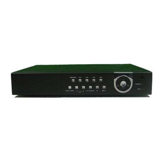
Page 8: Panels And Remote Controller
2. Panels and Remote Controller 2.1 Front Panel 1. LEDs Indicators for POWER and HDD access. 2. Remote IR PORT 5. Alpha-numeric buttons (1-4, *, #) Press these buttons for camera selection in most of the circumstances. These buttons can also be used to enter text and number in the way similar to most of the mobile phones. - Page 9 15. Left/Right buttons (◄,►) In PTZ control, press these buttons to pan the camera. In playback mode, press these buttons for fast backward/forward. In the other screens, press these buttons to move the cursor or focus window. 16. Up button (▲) Press this button to move the cursor or focus window in most circumstances.
-
Page 10: Panel
2.2 Back Panel 1. Video Input Connectors (CH1 - CH4) Connect system cameras to these BNC connectors. 2. Call Monitor Output Connector (CALL OUT) Connect CCTV monitor to this BNC connector for call monitor display. 3. Main Monitor Output Connectors (MAIN OUT) Connect CCTV monitor to the BNC connector for main monitor display. - Page 11 according as per Alarm Setup as described in Section 6.3. 11. Ethernet Connector (LAN) Connect this DVR to a 10/100Base-T Ethernet network through this port. 13. Power Cord Inlet (DC 12V) Connect DC 12V-5A power source. 14. USB connector (USB) Connect to USB 2.0 compatible storage device, such as USB 2.0 disk drive, DVD+RW, card reader, etc.
-
Page 12: Remote Controller
2.3 Remote Controller The remote controller is an accessory to ease the user’s operations. You can do all the operations by the remote controller instead of the buttons on the front panel. The effective distance is about 10 meters without any obstacle. The Buttons Each of these buttons corresponds to one of those buttons on the front panel. - Page 13 Main monitor Connect the main monitor output connector (BNC) to a surveillance monitor or connect the VGA output connector to a VGA monitor. The CCTV/VGA monitor displays selected live or recorded cameras in any available split window format. Hard disk drive Make sure to install one SATA hard disk (Max.
-
Page 14: Connections
3.2 Optional Connections Audio input Connect the audio input connector to the audio line-out from system cameras or other audio source. Please make sure to associate the audio input with the camera in Camera Setup as described in Section 6.2. Audio output Connect the audio output connector to the audio line-in of the speakers. -
Page 15: Main Screen And Basic Operations
4. Main Screen And Basic Operations The quad screen, as shown above, is the main screen after system startup. There are two types of split window screens, including Full Screen and Quad. The system will remember the last one before normal shutdown (as described in Section 5.6) of the system. -
Page 16: Text Input
4.1 Text Input (with remote control) There are certain circumstances that the system requires the user to enter text, such as system login, camera title setup and so on. Please follow the steps below to enter text: (1) Press ENTER to edit the highlighted option. The flashing cursor will be shown to indicate the editing point. -
Page 17: Login And Logout
4.2 Login And Logout There are three password levels in the system, including Administrator (highest), Supervisor and Operator (lowest). If the user does not login the system, he/she will be treated as “Guest” and can only view live video display. The system allows up to 18 user accounts. - Page 18 SEARCH (Administrator/Supervisor) In quad display, press this button to display the search menus. The system will remember the last one the user chose. Press this button to force manual recording. To stop manual recording, press it again. All cameras will be recorded as if the scheduled record is A/V and REC icon will be shown on the lower-right corner of the screen if manual recording is ON.
-
Page 19: Zoom
4.4 Digital Zoom The system supports X2/X4 Digital Zoom function. To use this function, press X2 button in full screen display to enter Digital Zoom mode. There will be a zoom window shown in the video window as shown. The zoom window (a) will always be shown at zoom factor X1, (b) can be shown or hidden at zoom factor X2 and (c) will never be shown at zoom factor X4. -
Page 20: Display
5. Menu Display In quad display, press MENU to call up Menu display as shown. There are a variety of displays under Menu display. In Menu display and all the subsequent displays, the items enabled are shown in black-colored text and those disabled in white-colored text. -
Page 21: Video Adjustment
5.2 Video Adjustment In Menu display, press ▲▼ to change the highlighted option to Video Adjustment and then press ENTER to call up Video Adjustment display as shown. There are 4 items which can be adjusted, including Brightness, Contrast, Hue, and Saturation. The operations are as below: ▲▼... -
Page 22: 5.3 Vga Display
5.3 VGA Display In Menu display, press ▲▼ to change the highlighted option to VGA Display and then press ENTER to call up VGA Display dialog as shown. There are 5 items which can be adjusted, including Resolution (1280x1024, 1024x768, 800x600, 640x480), Brightness, Contrast, Hue, and Saturation. - Page 23 The operations are as below: ▲▼◄► Press these buttons to select the items. Press this button to escape from this screen and return to previous display. Connect/Disconnect – If the backup device is disconnected (as shown in Current Status), please plug the device in the backup ports (USB) and/or insert a DVD for DVD device and then press ENTER to command the system to connect with it.
- Page 24 Some USB 2.0 Devices Tested USB-Storage Enclosures 5.25” – Macpower’s Alumni Prefect USB 2.0 - PF-U2MS USB-Disk Storage – Transcend’s JetFlash 150/V60 Series Apacer’s Handy Steno AH220 Pretec’s i-Disk Wave 512M-Black Kingston’s DataTraveler USB Flash Driver(DTI/512FE) SanDisk’s Cruzer micro USB Flash Driver Sony’s MICRO VAULT Classic Series DVD Writer –...
-
Page 25: Software Upgrade (Administrator)
5.5 Software Upgrade (Administrator) In Menu display, press ▲▼ to change the highlighted option to Software Upgrade and then press ENTER to call up Software Upgrade display as shown. The operations are as below: ▲▼◄► Press these buttons to select the items. Press this button to escape from this screen and return to Menu display. -
Page 26: System Shutdown (Administrator)
5.6 System Shutdown (Administrator) In Menu display, press ▲▼ to change the highlighted option to Shutdown and then press ENTER to shutdown the system. A confirmation dialog will be shown on the screen, press ENTER to confirm the shutdown. The system will save all the files and all the states and then display a power-off message in the rolling screen message area. -
Page 27: Pre-Camera Setup
6.1 Pre-Camera Setup In Setup Menu display, press ▲▼ to change the highlighted option to Pre-Camera and then press ENTER to call up Pre-Camera Setup display as shown. There are up to 4 cameras which can be connected to the system. The Pre-Camera Setup allows the administrator to define some fundamental attributes for all the installed cameras. -
Page 28: Setup
6.2 Camera Setup In Setup Menu display, press ▲▼ to change the highlighted option to Camera and then press ENTER to call up Camera Setup display as shown. The Camera Setup allows the administrator to define the attributes for each camera. There are up to 4 cameras which can be connected to the system. - Page 29 Motion Detection – whether the motion detection of this camera is enabled or not. Press ENTER or +/- to check/uncheck this item. The default setting is “ˇ ˇ ˇ ˇ ” - checked. Motion Settings.. – used to setup the motion settings for this camera. Press ENTER in Settings.. to call up Motion Setup display for the camera.
-
Page 30: Setup
6.2.1 Video Loss Setup In Camera Setup, press ENTER to call up Video Loss Setup of the selected camera as shown when the highlighted option is Video Loss Settings.. of the camera to setup. The Video Loss Setup allows the administrator to define how the system responds to the detected video loss for the camera. The general operations are as below: ▲▼... - Page 31 E-mail – to send the event e-mail to remote station or not. The e-mail will be sent to the predefined receivers at the moment when the event is triggered. Press ENTER or +/- to check/uncheck this item. The default setting is “– – – – ” - unchecked. 6.2.2 Motion Setup In Camera Setup, press ENTER to call up Motion Setup as shown when the highlighted option is Motion Settings..
-
Page 32: Motion Setup
Following is a brief description for each item and its specific operations: Duration – response duration to define at most how long (in seconds) the Alarm Out relay and the Buzzer will keep being triggered after motion is detected for this camera. However, the Alarm Out relay and the Buzzer will be reset immediately once the camera returns to normal. - Page 33 Following is a brief description for the operations: Numeric Press these buttons to select the camera. ▲▼◄► Press these buttons to move the mask window. Press these buttons to resize the mask window. ENTER Press this button to set/reset the area under the mask window. MODE Press this button to set/reset the whole video area.
- Page 34 6.3 Alarm Setup In Setup Menu display, press ▲▼ to change the highlighted option to Alarm and then press ENTER to call up Alarm Setup display as shown. The Alarm Setup allows the administrator to define the attributes for each alarm input and the actions if it’s triggered. There are up to 4 alarm inputs which can be connected to the system.
-
Page 35: Setup
Goto Preset – to define the preset position to go to for the Focus Camera if this alarm input is triggered and the Focus Camera is a PTZ camera. For more details about preset locations, please refer to Chapter 7 PTZ Control. - Page 36 The general operations are as below: ▲▼◄► Press these buttons to select the items. Press this button to escape from this screen and return to Setup Menu display. If the Save dialog is shown, press ENTER to exit and save, ESC to exit without saving. Following is a brief description for each item and its specific operations: Total Pages –...
-
Page 37: Setup
6.5 Scheduled Record Setup In Setup Menu display, press ▲▼ to change the highlighted option to Scheduled Record and then press ENTER to call up Scheduled Record Setup as shown. The Scheduled Record Setup allows the administrator to define when and how to record for the system. -
Page 38: Setup
Motion – record mode (No, Video or Audio/Video) when motion is detected for certain camera. Press +/- buttons to change the value. Normal – normal record mode, including No, V (Video only) or A/V (Audio/Video). Press +/- buttons to change the value. 6.6 HDD Setup In Setup Menu display, press ▲▼... -
Page 39: Format/Clear
Auto Overwrite – automatic overwrite of the recorded video/audio from HDD#1 when the Alarm/Normal Record disk drive capacity reaches the end of the last HDD. If Auto Overwrite is disabled and the Alarm/Normal Record disk drive capacity reaches the end, the system will not overwrite the recorded video/audio and hence not record Alarm/Normal video/audio, until the user presses the Alarm Reset button. - Page 40 The general operations are as below: MODE => Format Press this button to format the HDD. A confirmation dialog will be shown on the screen, press ENTER to confirm or ESC to cancel. Please note that it would take about 40 seconds to format a brand new HDD.
-
Page 41: Setup
6.7 Password Setup In Setup Menu display, press ▲▼ to change the highlighted option to Password and then press ENTER to call up Password Setup as shown. The Password Setup allows the administrator to add new users, delete existing ones and/or modify the user’s name, password and/or level. - Page 42 Level – the password level (Administrator, Supervisor or Operator) for this user. Press +/- buttons to change the level. 6.8 System Setup In Setup Menu display, press ▲▼ to change the highlighted option to System and then press ENTER to call up System Setup as shown. The System Setup allows the administrator to set the system time, time zone, time synchronization, language, etc.
-
Page 43: Setup
Date – system date. Press +/- buttons to modify each of these items. Time – system time. Press +/- buttons to modify each of these items. Display Format – format used for the system time displayed on the lower-left corner of the main screen. -
Page 44: Setup
Data Bit – press +/- buttons to change the value. Stop Bit – press +/- buttons to change the value. Parity – (Odd, Even, or None). Press +/- buttons to change the value. DVR/Camera ID – for PTZ => the device ID for this digital video/audio recorder must not conflict with the other devices connected in the same control port. - Page 45 IP Address – Ethernet IP address for the system. To get the static IP address, please contact your local ISP (Internet Service Provider). Please follow the Text Input method described in Section to modify these items. Net Mask – Net Mask for the IP address. Please follow the Text Input method described in Section 4.1 to modify these items.
- Page 46 6.10.1 E-mail Setup In Network Setup, press ENTER to call up E-mail Setup as shown when the highlighted option is E-mail. The E-mail Setup allows the administrator to set e-mail related parameters. When an event occurs and E-mail is enabled for the corresponding action, an e-mail will be sent based on the parameters set here.
-
Page 47: Advanced Network Setup
Mail To #1-5 – the receivers’ e-mail addresses. The system can send the e-mails originated from the triggered events to up to 5 different receivers. Please follow the Text Input method described Section 4.1 to modify these items. Attachment – attached picture for the e-mail sent. The value could be (N/A, Original picture, QCIF picture). -
Page 48: Ptz Control
7. PTZ Control The digital video/audio recorder supports a variety of PTZ cameras. The user can easily control the PTZ cameras through the operations described in this Chapter if the PTZ cameras have been connected and setup correctly. Please refer to Section 3.2 Optional Connections for the connections. - Page 49 Miscellaneous function specific operations: Active function Operations Descriptions Focus Focus far/near ENTER Auto focus Iris Iris increase/decrease Auto Pan (3) Auto pan speed is shown in parenthesis Increase/decrease speed ENTER Start/stop Auto Pan Set start position Set end position SEQ (5 sec.) SEQ dwell time is shown in parenthesis.
-
Page 50: Search By Time
8.1 Search By Time The screen for Search By Time is shown on the right side: The Status field will show the ‘Recorded from’ time based on the selected Video/Audio before searching - alarm partition if any of Alarm, Motion, or Video Loss, is checked and normal partition if Normal is checked. - Page 51 8.2 Search By Event / Log Display The screen for Search By Event - Log display, is shown below: There are four different types of event logs, including Alarm, Motion, Video Loss and System. Up to 1000 most recent event logs can be stored in the system. The general operations are as below: ▲▼◄►...
-
Page 52: Search Archived Files
Source ID – the source which triggered the event. For Alarm, it’s the alarm input number; for Motion and Video Loss, it’s the camera number. It’s used to filter the events to be shown in the log list. Press ENTER or +/- to check/uncheck each item. Log List –... - Page 53 Archived File List – the archived files in the selected Disk Storage. Please select the file and then press ENTER to enter Archived File Playback display of the selected file in this list or press Play Button ( ) to playback it directly. Please refer to Section 8.6 Playback For Archived for the detailed operations.
- Page 54 Following is a brief description for the operations in Backup display: ▲▼◄► Press these buttons to select the items. Copy Button ( Press this button to start backup (copy) or apply the revised settings if it’s copying and return to the previous display. There will be a Copy icon on the lower-right corner indicating that the selected video/audio is being archived to the storage device.
-
Page 55: Playback For Archived Files
End Time – (Year, Month, Date, Hour, Minute) for the recorded video/audio for the backup without playback of Search By Time. The files will be backup from the start time to the end time entered here when the user press the COPY button to start copying. Press +/- buttons to modify each item. - Page 56 Before Logging On Before accessing this unit through web browser, please make sure the followings (For most PCs, only step 3 & 6 is needed!): 1. The unit is connected to the network correctly and the configurations are all setup correctly. Please refer to Section 6.10 Network Setup for the detailed configurations.
- Page 57 The video images can be displayed in several types of quad screens, including 1/4/9/16-window. The focus window is surrounded by a frame border. In addition to the video windows, there are different icons on the lower corner and the right corner of the screen for status display and control. (The “.L” following the camera title stands for Live display, “.P”...
- Page 58 Click on this icon to freeze/unfreeze the video images for all the video windows. Click on this icon to enable/mute the audio input from the PC, button down for enable, button up for mute. If enabled, the audio input from the PC will be sent to the DVR. The default setting is ‘mute’. Click on this icon to enable/mute the audio output from the camera for the focus window, button down for enable, button up for mute.
- Page 59 Alarm Out Alarm outputs 1-2 (GREEN for normal state, RED for triggered state) for the DVR. For Administrator, click on any of these icons to control the corresponding alarm output from normal to triggered or from triggered back to normal. Click on this icon to call up Search-by-time dialog.
- Page 60 Following is a brief description for each item: Device Name – any meaningful name for the (DVR) device. Address – IP address or URL domain name for the (DVR) device. It should be the same as the IP address (for Static IP) or URL (for PPPoE) in Network Setup for the (DVR) device. Control Port –...
- Page 61 System Requirements of Remote PC It is recommended to access the digital video/audio recorder using a PC that meets the following system requirements. If you use a PC that does not meet the following system requirements, it may cause problems such as slow imaging or the browser unable to operate. IBM PC/AT compatible.
- Page 62 10. PDA/Mobile Phone Remote Access The digital video/audio recorder can also be remotely accessed by using a web browser installed on a PDA or mobile phone that (1) supports xHTML and MJPEG file format and (2) has screen resolution at 320x240 or above. Please enter the domain name or IP address of the digital video/audio recorder in the Location/Address field of the web browser and the remote login display will be shown.
- Page 63 Appendix A--MS-Windows HemPlayer There are several MS-Windows utility programs in the bundled CD, HemPlayer, KCtrl Simulator and AVI Converter. The HemPlayer is meant to play archived/backed up files on local PC. The AVI Converter utility converts H.264 files to standard *.AVI files. Please insert the CD in the CD-ROM or DVD-ROM drive in your PC and then double click on Setup.exe vcredist_x86.exe...
- Page 64 The user may print the whole player screen (including the current video image) or the current video image by selecting File menu and then select Print or Print Video respectively. KCtrl Simulator To run the Keyboard Control Simulator under MS-Windows, please select Start->Programs->Hyper Electronics Mappers->KCtrlSimulator and the screen will be shown as below.
- Page 65 AVI Converter To run the H.264 to AVI Conversion Utility under MS-Windows, please select Start->Programs->Hyper Electronics Mappers-> AVI Converter or double-click on the file AVI_Converter.EXE, and the screen will be shown as below. Please select the source files –.H264 files archived from DVR, remote I.E., HemPlayer, select the target directory to save the converted files and then click on OK to do the conversion.
-
Page 66: Motion Detection Setup
Menu Search Escape Sequence Fold tools Fast backward Fast forward Step forward Unfold tools Play/Pause Stop Copy Alarm reset Live/Playback Full screen Volume Page up Page down Close Motion detection setup Move the cursor to Menu -> -> Setup -> ->... - Page 67 PTZ setup The function is as follows in the PTZ controls the appearance Go to Figure down Zoom Figure up Preset Focus Auto Focus Iris position Auto pan Speed Mark Video adjustment icons This camera default All camera default Default Common icons Down Enter...
-
Page 68: System Setup
Appendix C – Specifications System O.S. Embedded Linux 2.6 Multiplex Sixfold operation - simultaneous record, live, playback, backup, control, & remote access Certification FCC, CE, LVDS, etc. Video Format NTSC/EIA or PAL/CCIR Input 4-CH, BNC, 1Vp-p/75ohm Main monitor BNC x 1, 1Vp-p/75ohm VGA D-SUB 15-pin connector x 1 Call monitor BNC x 1, 1Vp-p/75ohm... -
Page 69: E-Mail Setup
Network Ethernet 1 RJ-45 10/100BaseT Ethernet connector Remote setup, monitoring, backup, alarm notification, & remote software upgrade E-mail Alarm notification to stationary or mobile devices Video 1/4 quad & SEQ mode Audio Bidirectional Protocol TCP/IP, HTTP, PPPoE, DHCP, DDNS, TSP Remote users Up to 5 users simultaneously Bandwidth... - Page 70 Appendix D – Recording Table NTSC Recording Time (in Hour) - For Reference Only System Storage (GB): 200 Average Recording Rate (IPS) Resolution Quality Picture Size (KB)* 120 60 32.2 720x480 (Full D1) 27.7 21.0 18.4 14.0 11.3 1443 1984 514 1029 1543 3086 720x240...
- Page 71 PAL Recording Time (in Hour) - For Reference Only System Storage (GB): 200 Average Recording Rate (IPS) Resolution Quality Picture Size (KB)* 100 50 12.5 720x576 42.0 36.0 (Full D1) 27.3 21.3 18.3 14.7 10.0 1389 1903 946 1478 2955 720x288 21.0 18.0...
- Page 72 Via Don Arrigoni, 5 24020 Rovetta S. Lorenzo (Bergamo) http://www.comelit.it – E mail: export.department@comelit.it...
Need help?
Do you have a question about the 49134 and is the answer not in the manual?
Questions and answers