
Related Manuals for Comelit SDVR040A


Summary of Contents for Comelit SDVR040A
-
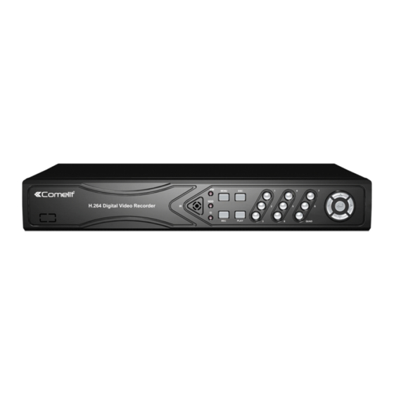
Page 1: Digital Video Recorder
4-8-16 INPUTS H264 STAND-ALONE DIGITAL VIDEO RECORDER ART. SDVR040A SDVR080A SDVR160A Please read this manual thoroughly before use and keep it for future reference... -
Page 2: Table Of Contents
Contents Chapter One Product Description ......................2 1.1 General Description ........................2 1.2 Technical Parameters ......................... 2 1.3 Open Case And Connect Cable……………….……..............3 1.3.1 Open case inspection ………....................3 1.3.2 HDD Installation........................3 Chapter Two Structure Appearance Description ..................4 2.1 Panel Description ........................4 2.2 Product Interface Description .................... -
Page 3: Chapter One Product Description
3.9.3 System Log ........................22 3.10 System Logout ........................22 ESEE user manual ……………....................23 Chapter one Product Description General Description This equipment is designed specifically for the field of a number of digital security surveillance products, which uses an Embedded Processor Init (MPU) and operating systems, combined with the field of the latest IT technologies, such as video and audio encode/decode, high-capacity hard disk recorder, TCP / IP network technology, code in FLASH, making system operation more stable. -
Page 4: Open Case And Connect Cable
Alarm Input 4 ch 4 ch 4 ch Alarm Output RS485 HardDisk 1 SATA 2 SATA 2 SATA Interface Network RJ45 10M/100M self-adaptive Ethernet interface USB Interface 2USB2.0 high-speed interface Power 12 VDC Open Case And Connect Cables 1.3.1 Open-case inspection First of all, please check if there is apparent damage of the packing as soon as you received the products. -
Page 5: Chapter Two Structure Appearance Description
Chapter Two: Structure Appearance Description Panel Description 1. POWER led 9. PTZ: PTZ key 2. 1 ~ 4: CH1 ~ CH4 Single-Screen keys 10. ESC: Exit key 3. QUAD key 11. MENU: Menu key 12. ▲▼◄►: Direction key 4. State led, reserved 5. - Page 6 1. HDD led 9. PLAY: Playback key 2. State led, reserved 10. ESC: Exit key 3. 1 ~ 8: CH1 ~ CH8 Single-Screen keys 11. MENU: Menu key 4. ▲▼◄►: Direction key : Confirm key 5. POWER led 13. N.C. 6.
-
Page 7: Product Interface Description
Product Interface Description 4 channels DVR Rear Panel 1. VIDEO IN: CH1 – CH4 video input 2. OUT V: analog video output 3. OUT A: audio output 4. AUDIO IN 1-2: audio input 5. VGA: VGA video output 6. ALARM: alarm input / output 7. -
Page 8: Remote Control Description
7. POWER key 8. ALARM: alarm input / output 9. HDMI: HDMI video output 10. VGA: VGA video output 11. NET: RJ45 network interface 12. USB interface 13. RS485 14. DC12V power supply 15. Fan Remote Control Description POWER Power switch Device button: after press"... -
Page 9: Chapter Three Description For Operation System
the same number. Chapter Three: Description of Operation System Turn ON / OFF Confirm that AC voltage accessible matches with DVR. Ensure that the DVR power outlet connect with a good middle ground grounding. After switching power, the device started, 【POWER】 light is on. -
Page 10: Esc Menu
b) After input the information, click 【OK】 【CANCEL】 button or button【ESC】can safe or exit (5) Button: used to implement a specific function or enter the next setup menu, click【OK 】 key and the left mouse button. 3.3.3 ESC MENU Press 【MENU】, 【ESC】 or the right mouse button to exit the menu mode Click the right mouse button and return to the previous menu level. -
Page 11: Video Search
3.5.1 Video Search means selected, means Channel:to choose the target channel by clicking the check box. non-selected means selected, means Record mode:to choose the recode mode by clicking the check box. non-selected Search time:input the Starting and finishing time into edit box Search:... -
Page 12: Ptz Control
Manual record menu include several parts: Channel: ☑ ”means open; “□”means close. All on: start all the channel. All off: close all the channel. OK: confirm and exit Cancel: click cancel can exit the manual record interface and back to main menu. Remarks: the video which start by manual must be turned off by manual, otherwise the recording will be always continue. -
Page 13: Video Backup
3.8.2 Video backup Choose the channel, and record mode; setup the search time, then begin search the file. After choosing the needed file from list box, click backup and ok, wait for process bar until 100% and show backup success. Note:USB driver pen must be FAT32 format when backup the file. -
Page 14: General Setup
3.8.3.1 General setup Choose the "General setup" and turn into it's setup interface. Time: DVR preview time. Click “refresh” after setting, it will pop out " the recording will stop once you modify the time", and save the setting. Date Format: Y/M/D”、“D/M/Y”、“M/D/Y” Auto Logout: DVR will log off if there is no operation within 10 minutes, it needs login again. -
Page 15: Record Setup
Select “encond setup” in system setup. Channel :choose the right CH you need by clicking the select box Stream: choose the right stream you need : "main stream" or "sub stream " Encode mode:choose the right encode model you need : "video only "means only encoding for video ;... -
Page 16: Network Setup
Select “record setup” in system setup. Channel :chose the target channel by clicking the select box Weekday : chose the correspond day as user's need, "ALL" means record all date. Recording mode and time:in the time edit box, user can set different time with different recoding mode . -
Page 17: Screen Setup
Data port: this port number is used for device and mobile visit ; suggest to set the port above 2000. NOTE: To view images of DVRs art. SDVR040A, SDVR080A and SDVR160A from smartphones (iOS or Android OS) please use the app "ESEENET+" which is freely downloadable from the relative stores (Apple Store and Play Store). -
Page 18: Video Detection
Select “screen setup” from “system setup” menu Channel:chose the target channel by clicking select box. Camera title:user can edit the channel title from the edit box. “ ☑ ” means display channel title, “□”means non-display. OSD Alpha: user can adjusted the OSD menu transparency as needed. OSD time:“... -
Page 19: Ptz Setup
Copy to : select the channel and click "copy to" & ''ok " to copy the same setting to other channel. Or user can choose copy to "all" to make all channel in same stetting . Click button "cancel", the setup information will be non-saved but exit. -
Page 20: System Tools
In "system setup" menu , choose "PTZ setup" to enter it's setting interface. Channel:chose the target channel by clicking select box. Work mode: select disable or able to stop the alarm or start the alarm. Alarm duration: set up alarm duration time. Recording channel: select the target channel to make recording after alarm is triggered. -
Page 21: Hdd Management
click" user management ". Add user: input a new user name in the edit box and set up the operational authority. Choose in the right check box, “ ☑ ” means the users can use it, “□” users cannot use it. Click the "set password " to set the new password, or it can be the default password. -
Page 22: Factory Setting
In " management tool", click "system maintenance", enter setting interface Auto reboot: setting automatic reboot time, it can set" Saturday to Sunday" . "Never" means do not reboot automatically Firmware upgrade: copy firmware to the root USB disk, insert USB, select the USB storage device, then click "start"... -
Page 23: System Version
info 3.9.1 HDD info The list box shows current HDD status info 3.9.2 System version Device name, device model, H/W version, S/W version could be checked here 3.9.3 System log Choose log type which need to check from list box, and input log time in the edit box, then click" search", log detail will showed below, you can turn the page by click "... - Page 24 3.10 System logout In main menu, click "system logout", popup setting interface User logout: Logout current user. After logout, if you want to use the device again, need to login System reboot: It will reboot when click "OK" Esee User Manual Connect DVR with network, make sure network working fine Enter router to enable UPNP.As below picture, it is TP-LINK router.
- Page 25 IP address: Default 192.168.1.114 (User input correct IP according IP actual situation, if in 1 network segment, input 192.168.1.114, if in 0 network segment, input 192.168.0.114 ).If no IP conflict, do not need to change 114 to other IP Subnet mask: In order to distinguish subnet segment, default 255.255.255.0 Default gateway: Default 192.168.1.1 (Change according to actual situation).
- Page 26 Remote Video Viewer After connecting, remote video viewer includes: preview window, PTZ control, preview mode, stream option, channel on/off, setting, configuration, playback, user logout, as below : Open preview: In preview window, click left mouse, choose target channel, (If channel frame is red,...
- Page 27 2 – verify that on the device, nearby label showing the model, is present the label with the univocal Technical code for the service registration. In case it was not present, contact Comelit support 3 – connect to the site http://www.comelitdns.com...
Need help?
Do you have a question about the SDVR040A and is the answer not in the manual?
Questions and answers