Table of Contents
Advertisement
Quick Links
Advertisement
Table of Contents

Related Manuals for Comelit 49808


Summary of Contents for Comelit 49808
-
Page 1: Digital Video Recorder
8-16 INPUTS H.264 STANDALONE DIGITAL VIDEO RECORDER ART. 49808-49816 Please read this manual thoroughly before use and keep it for future reference. Via Don Arrigoni, 5 24020 Rovetta S. Lorenzo (Bergamo) http://www.comelit.eu – e-mail: export.department@comelit.it... - Page 3 Digital Video Recorder art. 49808-49816 WARNINGS AND CAUTIONS WARNING TO REDUCE THE RISK OF FIRE OR ELECTRIC SHOCK, DO NOT EXPOSE THIS PRODUCT TO RAIN OR MOISTURE. DO NOT INSERT ANY METALLIC OBJECT THROUGH THE VENTILATION GRILLS OR OTHER OPENINGS ON THE EQUIPMENT.
- Page 4 User’s Manual FCC COMPLIANCE STATEMENT FCC INFORMATIONS: THIS EQUIPMENT HAS BEEN TESTED AND FOUND TO COMPLY WITH THE LIMITS FOR CLASS A DIGITAL DEVICE, PURSUANT TO PART 15 OF THE FCC RULES. THESE LIMITS ARE DESIGNED TO PROVIDE REASONABLE PROTECTION AGAINST HARMFUL INTERFERENCE IN A RESIDENTIAL INSTALLATION.
-
Page 5: Important Safeguards
Digital Video Recorder art. 49808-49816 Important Safeguards 1. Read Instructions 14. Damage requiring Service All the safety and operating instructions should be read before the Unplug this equipment from the wall outlet and refer servicing to appliance is operated. qualified service personnel under the following conditions: A. -
Page 6: Table Of Contents
User’s Manual Table of Contents Chapter 1 — Introduction ......................1 Feature........................... 1 Technical Overview........................ 1 Chapter 2 — Installation......................3 Package Contents........................3 Required Installation Tools ....................3 Video Input......................... 3 Video Loop Through ......................3 RS485 Port ........................4 Alarm Input/Output ...................... - Page 7 Digital Video Recorder art. 49808-49816 Network..........................17 Notification ........................20 Devices Setup ........................21 Camera ..........................21 Audio..........................22 Alarm-Out Screen ......................23 Display ..........................24 Remote Control ....................... 26 Recording Setup ........................26 Record ..........................26 Schedule.......................... 28 Pre-Event......................... 30 Event Setup .........................
- Page 8 User’s Manual Search Example I ......................59 Search Example II ......................59 WebGuard..........................60 Web Monitoring Mode ..................... 61 Web Search Mode ......................62 Time Overlap ........................64 Map of Screens ........................65 Connector Pin Outs......................66 I/O Connector Pin Outs ....................66 RS485 Connector Pin Outs .....................
- Page 9 Digital Video Recorder art. 49808-49816 Figure 34 — Remote Control setup screen..................... 26 Figure 35 — Record menu........................26 Figure 36 — Record Settings screen...................... 27 Figure 37 — Panic Record screen......................28 Figure 38 — Schedule setup screen....................... 28 Figure 39 —...
-
Page 11: Chapter 1 - Introduction
Digital Video Recorder art. 49808-49816 Chapter 1 — Introduction Feature Your color digital video recorder (DVR) provides recording capabilities for eight or 16 camera inputs. It provides exceptional picture quality in both live and playback modes, and offers the following features: 8 or 16 Composite Video Input Connectors Compatible with Color (NTSC or PAL) and B&W (CCIR and EIA-170) Video Sources... -
Page 12: Figure 1 - Typical Dvr Installation
User’s Manual Figure 1 — Typical DVR installation. NOTE: This manual covers the 8- and 16-channel digital video recorders. The DVRs are identical except for the number of cameras and alarms that can be connected and the number of cameras that can be displayed. For simplicity, the illustrations and descriptions in this manual refer to the 16-camera model. -
Page 13: Chapter 2 - Installation
Digital Video Recorder art. 49808-49816 Chapter 2 — Installation Package Contents The package contains the following: Digital Video Recorder Power Cord User’s Manual (This Document) RAS Software CD and User’s Manual Rack-mount Kit Assembly Screws for Adding Hard Disk Drives... -
Page 14: Rs485 Port
User’s Manual If you would like to connect your video source to another device, you can use the Loop BNC connectors. NOTE: The Loop BNC connectors are auto terminated. Do NOT connect a cable to the Loop BNC unless it is connected to a terminated device because it will cause poor quality video. -
Page 15: Audio In/Out
Digital Video Recorder art. 49808-49816 Audio In/Out Your DVR can record audio from up to four sources. Connect the audio sources to Audio In 1, Audio In 2, Audio In 3 and Audio In 4 as needed using RCA jacks. -
Page 16: Chapter 3 - Configuration
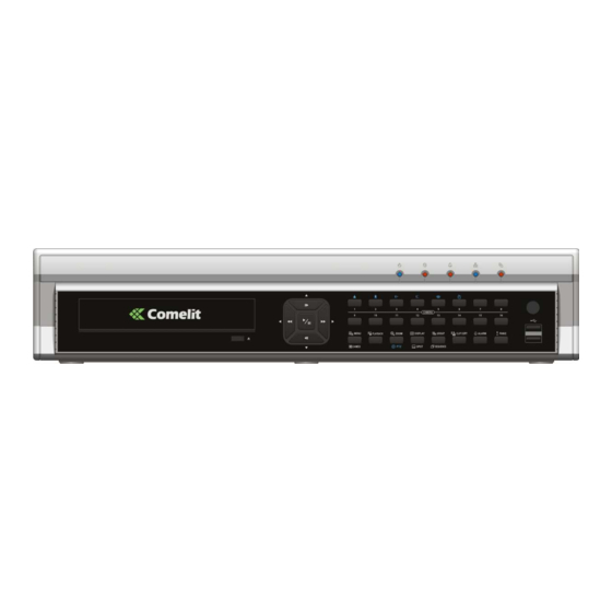
User’s Manual Chapter 3 — Configuration NOTE: Your DVR should be completely installed before proceeding. Refer to Chapter 2 — Installation. Front Panel Controls Figure 3 — 16-Channel DVR front panel. Power LED HDD LED Alarm Out LED Network LED Clip Copy LED Camera Buttons Play/Pause Button... -
Page 17: Power Led
Digital Video Recorder art. 49808-49816 Figure 4 — Infrared remote control. NOTE: For simplicity, the button descriptions in this manual refer to the front panel buttons. Power LED The Power LED is lit when the unit is On. HDD LED The HDD LED flickers when the DVR is recording or searching video on the hard disk drive. -
Page 18: Camera Buttons (1 To 16)
User’s Manual Camera Buttons (1 to 16) Pressing the individual camera buttons will cause the selected camera to display full screen. Buttons 1 to 9 are also used to enter passwords. In the PTZ mode, pressing the button 1 zooms in the screen and the button 2 zooms out the screen, pressing the button 3 focuses near and button 4 focuses far, and pressing the button 5 moves to the preset and button 6 saves the preset. -
Page 19: Zoom/Ptz Button
Digital Video Recorder art. 49808-49816 ZOOM/PTZ Button Pressing the ZOOM/PTZ button zooms in the current image in double on the screen. You can use the arrow buttons to move the rectangle to another area. Pressing the (Play/Pause) button zooms in the image in rectangle. -
Page 20: Id Button On Remote Control
User’s Manual ID Button on Remote Control If a DVR System ID is set to 0, the infrared remote control will control that DVR without any additional operations. (Refer to the System Information setup screen in this chapter for further information on setting the System ID.) If the system ID is 1 to 16, you must to press the button on the remote control and then press the number button (1 to 16) in order to control that DVR. -
Page 21: Setup Screen
Digital Video Recorder art. 49808-49816 Setup Screen Figure 7 — Setup screen. Press the button or move the mouse pointer to the top of the screen and then select (Setup) in the Live MENU Monitoring menu to enter the setup screen. -
Page 22: Figure 9 - Information Setup Screen
User’s Manual In the Information screen, you can name the site location, assign a System ID number, select the language the screens are displayed in, display software version number, upgrade the software, show the System Log, display recorded time data, and clear all data. Highlight the Site box and press the button. -
Page 23: Date/Time
Digital Video Recorder art. 49808-49816 Highlight Show System Log… and press the button to display the System Log. The System Log screen lists system activities (up to 5,000 from the latest) that have occurred along with the time and date. The icon will be displayed in the last column for system activities of the remote site. -
Page 24: Storage
User’s Manual You can set up holidays by highlighting + and pressing the button. The current date appears. Highlight the month and day and change them by using the Up and Down arrow buttons. Press the button to add the date. -
Page 25: User
Digital Video Recorder art. 49808-49816 Highlight the box in the Format column for the desired storage device and press the button. You will be able to format the device for recording. When selecting Not Using from Use As and highlighting the Format button, the device will not be used for recording. -
Page 26: Figure 15 - User Setup Screen
User’s Manual The +/- column is used to collapse and expand user groups. If there is a + or – in this column, it indicates the item is a Group Name. If there is a – in front of the Group Name, it indicates that the group has been “expanded”... -
Page 27: Shutdown
Digital Video Recorder art. 49808-49816 NOTE: In addition to using the front panel buttons or the infrared remote control, you can use the virtual keyboard to assign the password. To display the virtual keyboard click the button using the mouse (not supplied). -
Page 28: Figure 19 - Lan (Manual) Setup Screen
User’s Manual The DVR supports two-way audio communication between a local system and a PC running RAS. Highlighting the box beside Remote Audio Channel and pressing the button allows you to select the audio channel that sends audio to the remote site. Selecting Select From RAS will send audio of the channel selected from RAS. NOTE: Depending on network conditions, audio might be interrupted or out of synchronization during transmission. -
Page 29: Figure 20 - Dvrns Setup Screen
Digital Video Recorder art. 49808-49816 Selecting DHCP from the Type and highlighting Save button reads the current IP address of the DVR configured by DHCP (Dynamic Host Configuration Protocol) network. Selecting ADSL (with PPPoE) allows you to set up the ADSL network. -
Page 30: Notification
User’s Manual Highlight the box beside DVR Name and press the button. A virtual keyboard appears allowing you to enter the DVR name to be registered on the DVRNS server. Highlight the Check box and press the button to check whether or not the name you entered can be used. NOTE: The DVR name you entered should be checked by selecting Check, otherwise the DVRNS changes will not be saved. -
Page 31: Devices Setup
Digital Video Recorder art. 49808-49816 Highlight the box beside Authentication and press the button. An Authentication screen appears. Highlight Use and press the button to toggle between On and Off. Highlight the box beside User/Password and press the button. A virtual keyboard appears allowing you to enter the user ID and password. -
Page 32: Audio
User’s Manual You can turn the camera number On or Off, and you can change the Title of each camera using the virtual keyboard. You can also determine which cameras will display on the monitors by selecting Normal, Covert 1 or Covert 2 from a drop-down list in the Use column. -
Page 33: Alarm-Out Screen
Digital Video Recorder art. 49808-49816 The DVR can record up to four audio inputs. Highlight the box beside the input and press the button. A list of cameras appears, and you can select which camera you want associated with that audio input. -
Page 34: Display
User’s Manual box allows you to delete an alarm output schedule. You will be asked to confirm whether or not you really wish to delete the schedule. Display Highlight Display in the Devices menu and press the button. The Display screen allows you to select what information will be displayed on the monitor. -
Page 35: Figure 32 - Spot Monitor Screen
Digital Video Recorder art. 49808-49816 You can define the screen layout in a variety of formats and set the DVR to sequence through the different screen layouts (pages) so that all the cameras will be displayed. You can also set up the DVR to display one camera or a group of cameras all the time while cycling through the remaining cameras in a “cameo”... -
Page 36: Remote Control
User’s Manual Use the arrow buttons on the setup screen to move the VGA screen position in the direction you want. Selecting the default button at the center cancels the screen positioning operation and reloads the default position. Remote Control Highlight Remote Control in the Devices menu and press the button. -
Page 37: Figure 36 - Record Settings Screen
Digital Video Recorder art. 49808-49816 Highlighting Recycle and pressing the button toggles between On and Off. In the Recycle mode, the DVR records over the oldest video data once all available storage space has been used. When Recycle is turned off, the DVR stops recording once all available storage space has been used. -
Page 38: Schedule
User’s Manual Highlighting Use Panic Recording and pressing the button toggles between On and Off. Highlight the Panic Recording – Duration box and set the duration of panic recording. Panic recording will stop automatically after the preset duration as long as the PANIC button is not pressed to stop the panic recording. -
Page 39: Figure 39 - Schedule - Settings (Advanced Mode) Setup Screen
Digital Video Recorder art. 49808-49816 Highlight the box under the Range heading and press the button to change the time range that the scheduled recording will take place. The smallest time segment you can use is 15 minutes. Highlight the box under the Mode heading and press the button to change the recording mode that will be used. -
Page 40: Pre-Event
User’s Manual Highlighting boxes under Dwell and pressing the button allows you to set the length of time you would like to record for the associated event. (Advanced Mode Only) Pre-Event Highlight Pre-Event in the Record menu and press the button, and the Pre-Event setup screen appears. -
Page 41: Figure 43 - Alarm-In Actions 1 Screen
Digital Video Recorder art. 49808-49816 You can set up the DVR to start panic recording whenever it senses an input on one of its alarm input connectors. Highlight the box beside Panic Record and press the button. A list of Alarm Inputs appears, and you can select which alarm input you want associated with panic recording. -
Page 42: Motion Detection
User’s Manual Motion Detection Highlight Motion Detection in the Event menu and press the button. The Motion Detection setup screen appears. Your DVR has built-in video motion detection. Video motion detection can be turned On or Off for each camera. Figure 45 —... -
Page 43: Figure 46 - Motion Detection Actions 1 Screen
Digital Video Recorder art. 49808-49816 NOTE: The record action for motion events will not be affected by the Motion Ignoring function. Highlighting Daytime Setup and pressing the button allows you to set up the Daytime range. Highlight the box beside Daytime and press the button. -
Page 44: Video Loss
User’s Manual Video Loss Highlight Video Loss in the Event menu and press the button. The Video Loss setup screen appears. Highlighting the box under the Video Loss Interval heading allows you to set the duration of a signal loss before the DVR will report a Video Loss. -
Page 45: Video Blind
Digital Video Recorder art. 49808-49816 Highlight the desired box under the PTZ heading, and press button. A list of PTZ presets appear. Select the preset position for each PTZ camera, where you want PTZ cameras to move to when the DVR detects video loss on the selected camera’s input. -
Page 46: Text-In
User’s Manual The DVR can be set to react to video blind differently for each camera. Each camera can be associated with another camera, trigger an Alarm-Out connector, sound the DVR’s internal buzzer, notify a number of different devices, move PTZ cameras to preset positions, and/or display a camera on a SPOT monitor. -
Page 47: Figure 54 - Text-In Settings Screen
Digital Video Recorder art. 49808-49816 The DVR can be set to react to text input from devices such as ATMs (Automated Teller Machines) and POS (Point of Sale; i.e., cash registers). This screen allows you to configure the DVR for each text-in device. -
Page 48: System Event
User’s Manual Highlight the box beside Time Out, and press the button. Set the length of time to wait for the new text string. The DVR will consider a transaction complete if no new text strings are entered between the last text input and the dwell time out. -
Page 49: Figure 58 - Health Check Screen
Digital Video Recorder art. 49808-49816 The DVR can be configured to run self-diagnostics and report the results. Highlighting the box beside System and pressing the button allows you to select the interval that you want the DVR to run self-diagnostics on the system. You can select from 1 hr. to 30 days or Never. -
Page 50: Event Status
User’s Manual The DVR can be set to react to system events. System events can be associated with an Alarm-Out connector, sound the DVR’s internal buzzer, and/or notify a number of different devices. Highlight the Alarm-Out box beside the desired event (Check Recording, Check Alarm-In, Disk Almost Full, Disk Full, Disk Bad, Disk Temperature, or Disk S.M.A.R.T.), and press the... - Page 51 Digital Video Recorder art. 49808-49816...
-
Page 52: Chapter 4 - Operation
User’s Manual Chapter 4 — Operation NOTE: This chapter assumes your DVR has been installed and configured. If it has not, please refer to Chapters 2 and 3. The DVR’s controls are similar to a VCR. As with a VCR, the main functions are recording and playing back video. However, you have much greater control over recording and playing back video. -
Page 53: Live Monitoring Menu
Digital Video Recorder art. 49808-49816 Live Monitoring Menu Freeze Selecting (Freeze) in the Live Monitoring menu will freeze the current image on the screen until you select again. It is the same as pressing the (Play/Pause) button. Pressing any button except for the... -
Page 54: Active Cameo Mode
User’s Manual Alarm Reset Selecting (Alarm Reset) in the Live Monitoring menu resets the DVR’s outputs including the internal buzzer during an alarm. It is the same as pressing the button. ALARM Panic Selecting (Panic) in the Live Monitoring menu starts panic recording of all cameras, and selecting again stops panic recording. -
Page 55: Figure 63 - Ptz Select Camera Menu
Digital Video Recorder art. 49808-49816 To use the front panel buttons, press the Left and Right arrow buttons to pan left and right. Press the Up and Down arrow buttons to tilt the camera up and down. Press the button to zoom in, and press the button to zoom out. -
Page 56: Event Monitoring
User’s Manual Event Monitoring When an event occurs, the DVR will display the camera associated with the event if Event Monitoring On is selected in the Display setup screen (OSD tab). How the cameras are displayed depends on the number of cameras associated with the event. If one camera is associated with the event, the DVR will display the camera full screen. -
Page 57: Recording Video
Digital Video Recorder art. 49808-49816 Full Screen Previous Group Next Group Figure 66 — Mouse Display menu. Full Screen Selecting (Full Screen) in the Mouse Display menu and choosing the camera number button displays the selected camera full screen. It is the same as pressing the individual camera buttons on the front panel or clicking the left mouse button on a camera image when in one of the multiview formats (i.e., 2x2, 3x3 or 4x4). -
Page 58: Panic Recording
User’s Manual Panic Recording Selecting (Panic) in the Live Monitoring menu or pressing the button starts panic recording of all cameras, PANIC and selecting or pressing the button again stops panic recording. If you set the Panic Recording Duration in the Panic Record setup screen, panic recording will stop automatically according to the preset duration as long as not selected or the button is not pressed. -
Page 59: Searching Video
Digital Video Recorder art. 49808-49816 CAMEO Button: Pressing and holding the button for three seconds or longer enters the cameo mode. The yellow outline surrounding the video indicates the active cameo, and pressing the arrow buttons moves the active cameo. -
Page 60: Search Menu
User’s Manual Search Menu Search Selecting (Search) in the Search menu displays the following Search menu. See the following Event Log Search, Record Table Search, Calendar Search, Motion Search and Text-In Search sections for details. Event Log Search: Selecting Event Log Search selects video from the event log. Record Table Search: Selecting Record Table Search selects using a recording table. -
Page 61: Event Log Search
Digital Video Recorder art. 49808-49816 Panic Selecting (Panic) in the Search menu starts panic recording of all cameras, and selecting again stops panic recording. It is the same as pressing the button. PANIC Data Source (Data Source) in the Search menu allows you to select the data source to be searched. Selecting Record... -
Page 62: Record Table Search
User’s Manual Highlight the box beside Motion and press the button. You can select the cameras for which you want any reports of motion detection. Highlight the box beside Video Loss and press the button. You can select the cameras for which you want any reports of lost video. -
Page 63: Calendar Search
Digital Video Recorder art. 49808-49816 There are three view modes. Standard view, Expanded view and Compact view. Standard view (default) displays combined recording information of all camera channels currently displayed on the screen. In the Standard view mode, selecting the icon located at the bottom switches to the Expanded view mode. -
Page 64: Motion Search
User’s Manual NOTE: It is possible that no recorded image displays on the current screen. Press the button and DISPLAY change the screen mode to 4x4. You will be able to easily see the camera have recorded video during target time. Motion Search The Motion Search…... -
Page 65: Text-In Search
Digital Video Recorder art. 49808-49816 Text-In Search The DVR maintains a log of each time there is Text Input. The Text-In Search screen displays this list. Use the arrow buttons to highlight the event for which you would like to see video. -
Page 66: Clip-Copy
User’s Manual Clip-Copy Video clips can be copied on an internal DVD RW drive, or external USB hard disk or flash drive. The copied video clips can be viewed on computers running Microsoft Windows 98, ME, 2000, XP or Vista. Refer to the Appendix – USB Hard Disk Drive Preparation for information on preparing the external drive for clip copy. -
Page 67: Print
Digital Video Recorder art. 49808-49816 Highlight Verify After Burning and press the button. This will toggle between On and Off. When this feature is On, you can verify that the data is written on the DVD RW properly. Highlight Use Site Name and press the button. -
Page 68: Appendix
User’s Manual Appendix USB Hard Disk Drive Preparation Preparing the USB hard disk drive in Windows 2000 NOTE: Preparing a USB hard disk drive under Windows XP and Window Vista is almost identical to Windows 2000. Connect the USB hard disk drive to your computer using the USB Cable. Turn on your computer. -
Page 69: Text-In Search Examples
Digital Video Recorder art. 49808-49816 Text-In Search Examples Search Example I 123456789012345678901234567890123456789012345678901234567890 Item Unit price amount ================================================== Coke 2.20 | 1(s) | $ 2.20 Fanta 2.20 | 1(s) | $ 2.20 Hotdog 3.50 | 3(s) | $ 10.50 Pepsi 1.95 | 1(s) | $ 1.95... -
Page 70: Webguard
User’s Manual For example, if you want to search for Coke with a Qty (Quantity) of more than 1 and Hotdog with an amount totaling over $8, the following search condition can be set. WebGuard WebGuard allows you to access a remote DVR, monitor live video images and search recorded video using Internet Explorer web browser anytime from virtually anywhere. -
Page 71: Web Monitoring Mode
Digital Video Recorder art. 49808-49816 NOTE: The port numbers for WEBWATCH, WEBSEARCH and Audio should be the same port numbers used for Remote Watch, Remote Search and Remote Audio set during Network setup. When running the updated WebGuard for the first time, Internet Explorer might occasionally load the information of the previous version. -
Page 72: Web Search Mode
User’s Manual ⑤ Click the screen format to select the desired display mode. When changing the screen format, the selected camera on the current screen will be located in the first cell of the new layout. ⑥ Click the camera button (1 to 16) to select the camera to be viewed. ⑦... - Page 73 Digital Video Recorder art. 49808-49816 ① Click the to log out the WebGuard program. ② Click the to access to the web monitoring mode. ③ Position the mouse pointer on the WebSearch logo to see the version of the WebGuard program.
-
Page 74: Time Overlap
User’s Manual ⑭ Selecting a camera on the screen and clicking the right mouse button displays the text menu screen. Change Camera Title: Changes the camera name. Enable Audio: Plays audio while playing back recorded video that has recorded audio. (Single-Screen Layout Only) Aspect Ratio: Changes the image aspect ratio. -
Page 75: Map Of Screens
Digital Video Recorder art. 49808-49816 Map of Screens... -
Page 76: Connector Pin Outs
User’s Manual Connector Pin Outs I/O Connector Pin Outs AI (1 to 16) Alarm Inputs 1 to 16 Chassis Ground (6 connectors) Relay Alarm Output (Normally Closed) Relay Common Relay Alarm Output (Normally Open) Alarm Reset In RS485 Connector Pin Outs Master Unit Slave Unit TX+/ RX+... -
Page 77: System Log Notices
Digital Video Recorder art. 49808-49816 System Log Notices Boot Up Panic On Shutdown Panic Off Restart Clear All Data Upgrade Clear Disk Upgrade Fail Format Disk Power Failure Disk Full Time Change Auto Deletion Time Zone Change Search Begin Time Sync... -
Page 78: Specifications
User’s Manual System Upgrade Related Clip Copy Related Description Description Remote upgrade is not authorized. Opening executable file failed. Saving remote package failed. Writing executable file failed. Remote upgrade is cancelled by the user. Creating image failed. USB device mounting failed. Burning failed. - Page 79 Digital Video Recorder art. 49808-49816 CONNECTORS Video Input Composite: 8 or 16 BNC Video Loop Composite: 8 or 16 BNC (Auto Terminating) Composite: 1 BNC Monitor Output VGA: 1 VGA SPOT (Composite): 1 BNC Audio In 4 RCA connector Audio Out...
- Page 80 Business users should contact their supplier and check the terms and conditions of the purchase contract. This product should not be mixed with other commercial wastes for disposal. Via Don Arrigoni, 5 24020 Rovetta S. Lorenzo (Bergamo) http://www.comelit.eu – e-mail: export.department@comelit.it V1.0...
Need help?
Do you have a question about the 49808 and is the answer not in the manual?
Questions and answers