Table of Contents
Advertisement
Quick Links
Advertisement
Table of Contents

Related Manuals for Comelit 49107


Summary of Contents for Comelit 49107
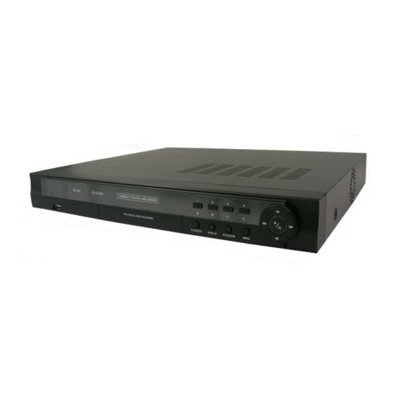
- Page 1 FOUR CHANNEL DIGITAL VIDEO RECORDER ART. 49107 Please read this manual thoroughly before use and keep it for future reference. Via Don Arrigoni, 5 24020 Rovetta S. Lorenzo (Bergamo) http://www.comelit.it – E mail: export.department@comelit.it...
- Page 3 Four-Channel Digital Video Recorder...
- Page 4 User’s Manual WARNINGS AND CAUTIONS WARNING TO REDUCE THE RISK OF FIRE OR ELECTRIC SHOCK, DO NOT EXPOSE THIS PRODUCT TO RAIN OR MOISTURE. DO NOT INSERT ANY METALLIC OBJECT THROUGH THE VENTILATION GRILLS OR OTHER OPENINGS ON THE EQUIPMENT. CAUTION Explanation of graphical symbols The lightning flash with arrowhead symbol, within an equilateral triangle, is intended...
- Page 5 Four-Channel Digital Video Recorder FCC COMPLIANCE STATEMENT. FCC INFORMATIONS: THIS EQUIPMENT HAS BEEN TESTED AND FOUND TO COMPLY WITH THE LIMITS FOR CLASS A DIGITAL DEVICE, PURSUANT TO PART 15 OF THE FCC RULES. THESE LIMITS ARE DESIGNED TO PROVIDE REASONABLE PROTECTION AGAINST HARMFUL INTERFERENCE IN A RESIDENTIAL INSTALLATION.
- Page 6 User’s Manual Important Safeguards 1. Read Instructions 13. Damage requiring Service All the safety and operating instructions should be read before the Unplug this equipment from the wall outlet and refer servicing to appliance is operated. qualified service personnel under the following conditions: A.
-
Page 7: Table Of Contents
Four-Channel Digital Video Recorder Table of Contents Chapter 1 — Introduction ..................1 Features ........................1 Package Contents ....................1 Rear Panel Connectors ..................1 Factory Reset ......................3 Front Panel Controls .....................3 Chapter 2 — Operation .....................4 Turning on the Power ....................4 Live Monitoring ......................5 Recording ......................5 Playback........................6 Searching ......................6... - Page 8 User’s Manual...
-
Page 9: Chapter 1 - Introduction
Four-Channel Digital Video Recorder Chapter 1 — Introduction FEATURES Your color digital video recorder (DVR) provides recording capabilities for 4 camera inputs. It provides exceptional picture quality in both live and playback modes, and offers the following features: 4 Composite Input Connectors Compatible with Color (NTSC or PAL) and B&W (CCIR and EIA-170) Video Sources Auto Detection for NTSC and PAL Auto Detection for VGA Monitor... - Page 10 User’s Manual Video In: Connect the coaxial cables from the video sources. Video Out: Connect a main monitor. VGA: Connect a VGA monitor. The VGA monitor is automatically detected when you connect it. Alarm In: Connect alarm-in devices. The threshold voltage for NC (Normally Closed) is above 4.3V and for NO (Normally Open) is below 0.3V, and it should be stable at least 0.5 seconds to be detected.
-
Page 11: Factory Reset
Four-Channel Digital Video Recorder FACTORY RESET To reset the unit, you will need a straightened paperclip: Turn the DVR off. Insert the straightened paperclip in the unlabeled hole to the right of the Alarm Output connector, and turn the DVR on. Hold the switch until the DVR turns on and live monitoring screen appears. -
Page 12: Chapter 2 - Operation
User’s Manual Chapter 2 — Operation TURNING ON THE POWER Connecting the power cord to the DVR turns on the unit. The unit will take approximately 30 seconds to initialize. The DVR provides five operation modes: live monitoring, recording, playback, searching and PTZ mode. When the DVR operates first, it displays quad screen and starts recording. -
Page 13: Live Monitoring
Four-Channel Digital Video Recorder LIVE MONITORING To Change Screen Mode Full-screen Pressing a camera button in quad screen mode displays that camera in full screen. Quad screen Pressing the DISPLAY button in full screen mode displays four cameras at once. Sequence screen Pressing the DISPLAY button in quad screen mode displays four cameras in... -
Page 14: Playback
User’s Manual To Enter Recording Mode Time-Lapse Recording Event Recording Main Menu RECORD Main Menu RECORD - Select in Record Mode. - Select in Record Mode. - Set up the recording speed and quality for - Set up the recording speed and quality for time-lapse recording. - Page 15 Four-Channel Digital Video Recorder To Enter Searching Mode Pressing the MENU button in the playback mode enters the Search mode and displays the Search Menu. Selecting Exit Search exits the search mode. Select the desired search mode in the search menu. Go To the First: Select to go to the first recorded image.
- Page 16 User’s Manual Clip Copy It allows you to copy recorded video clips to external storages. The copied video clips can be viewed on computers. Refer to Appendix – Clip Player. From/To: Set up to define a specific period of video to copy. You can simply sets the period of video to copy by using the PLAYBACK button on the front panel in the playback mode.
-
Page 17: Ptz Control
Four-Channel Digital Video Recorder PTZ CONTROL PTZ control is available for only PTZ cameras that allow pan, tilt, zoom, focus or preset etc. To Enter PTZ Mode Connect a PTZ device to the DVR and set up the PTZ device. Refer to Chapter 3 – Configuration Main Menu, PTZ for details. - Page 18 User’s Manual To Run Preset Pressing the MENU button in PTZ mode displays the PTZ menu. Move to Set Preset in the PTZ menu and select it by pressing the button displays the Set (Play/Pause) button. Pressing the Preset screen. Pressing the button again displays a virtual keyboard.
-
Page 19: Chapter 3 - Configuration
Four-Channel Digital Video Recorder Chapter 3 — Configuration OVERVIEW How to Enter Main Setup Menu Pressing the MENU button in the live monitoring mode enters a Main Setup menu. Entering a Main Setup menu is password protected. Enter the password by pressing the camera buttons or virtual keyboard (1 to 9), and a Main Setup screen appears. -
Page 20: Main Menu
User’s Manual How to Enter Characters Select the desired item and press button, and a virtual keyboard is displayed. Move to the desired character by pressing the arrow buttons, and enter the desired character by pressing the button and using space, (upper or lower case change),... - Page 21 Four-Channel Digital Video Recorder SYSTEM Language: Choose the desired language. OSD: Choose to enable or disable OSD (On Screen Display). None: Choose to not display OSD information. Camera: Choose to display camera title, recording status and PTZ icons on each camera screen. Status: Choose to display zoom, network connection, freeze, sequence and recycle icons, and date/time information on the bottom of the screen.
- Page 22 User’s Manual RECORD Recycle: Select to record over the oldest video data once all available storage space has been used. When it is not selected, the DVR stops recording once all available storage has been used. Resolution: Choose to set up the recording resolution. Event Record Dwell: Choose to set up the length of time to record for the associated event.
- Page 23 Four-Channel Digital Video Recorder EVENT The DVR can notify you when a motion is detected in a camera channel by sounding an alarm or beep or by sending an e-mail. No.: Select to set the video motion detection for entire cameras (No.) or an individual camera.
- Page 24 User’s Manual NETWORK Transfer Speed: Set up the transfer speed, and choose the unit of measure for the transfer speed between: bps (byte per second) and ips (image per second). Quality: Choose the quality for transferred image. NOTES: The higher Quality settings require higher Transfer Speed settings. The transfer speed you set is the maximum speed.
- Page 25 Four-Channel Digital Video Recorder Use DVR Name Service: Select to use DVR name service function. DVRNS Server: Enter the IP address or domain name of the DVRNS server. Port: Set up the port number of the DVRNS server. Use NAT: Select when using NAT. DVR Name: Enter the DVR name to be registered on the DVRNS server.
- Page 26 User’s Manual No.: Indicates a camera number. Product: Choose to select the model of installed PTZ device. ID: Choose to assign an ID to each PTZ device. Port: Choose to select the communication port. If the PTZ port is not set up, you will not be able to set up PTZ devices. Setup…: Choose to set up port speed, data bit, stop bit and parity of the connected device.
-
Page 27: Appendix
Four-Channel Digital Video Recorder Appendix WEBGUARD WebGuard allows you to access a remote DVR, monitor live video images and search recorded video using Internet Explorer web browser anytime from virtually anywhere. Computer system requirements for using the WebGuard program are: ®... - Page 28 User’s Manual NOTES: When running the updated WebGuard for the first time, Internet Explorer might occasionally load the information of the previous version. In this case, delete the temporary internet files by selecting Tools Internet Options General tab, and then run WebGuard again. You will need to get the appropriate IP address for the DVR you want to connect to and the WebGuard port number from your network administrator.
- Page 29 Four-Channel Digital Video Recorder ⑩ Save Image: Click to save the current image as a bitmap or JPEG file format. ⑪ Setup: Click to set up the image drawing mode and OSD display. You can adjust the display speed by changing the image drawing mode, and select OSD information to be displayed on the screen.
-
Page 30: Dvr Name Service (Dvrns)
User’s Manual ⑧ Time-lapse Search: Click to enter the time-lapse search mode which allows you to search for recorded data by time and then play back images found within the time parameters. The Timetable window located at the bottom displays the time information for the image of the date selected on the calendar. -
Page 31: Clip Player
Four-Channel Digital Video Recorder System Configuration STEP 1 (DVR DVRNS Server): Register the unit name and IP address of the DVR during the NETWORK – DVRNS setup. This unit name and IP address will be registered on the DVRNS server directly. STEP 2 (WebGuard DVRNS Server): Request the IP address of the DVR using the... - Page 32 User’s Manual The ClipPlayer Screen displays the clip images. : Select to go to the beginning of the video clip. : Select to play the video clip in fast forward. : Select to play the video clip in fast reverse. : Select to go to the end of the video clip.
-
Page 33: Time Overlap
Four-Channel Digital Video Recorder TIME OVERLAP If the DVR’s time and date have been reset to a time that is earlier than the existing recorded video, it is possible for the DVR to have more than one video stream in the same time range. In this case, you can search overlapping video streams individually by selecting a specific segment. -
Page 34: Error Code Notices
User’s Manual ERROR CODE NOTICES SYSTEM UPGRADE RELATED CLIP COPY RELATED Number Description Number Description Unknown error. Unknown error. File version error. Device error. Operating system version error. Mounting failed. Software version error. No media. Kernel version error. Invalid media. Upgrade device mounting failed. -
Page 35: Connector Pin Outs
Four-Channel Digital Video Recorder CONNECTOR PIN OUTS I/O Connector Output AI (1 to 4) Alarm Inputs 1 to 4 GND (Chassis Ground) Alarm Reset In Alarm Out (Normally Closed) Common Alarm Out (Normally Open) Input RS485 Connector Master Unit Slave Unit −... -
Page 36: Specifications
User’s Manual SPECIFICATIONS VIDEO Signal Format NTSC or PAL (Auto detect) Video Input Composite: 4 inputs, 1 Vp-p, auto-terminating, 75 Ohms Composite: One (BNC), 1 Vp-p, 75 Ohms Monitor Outputs VGA: One (Auto detect) Composite: 720x480 (NTSC), 720x576(PAL) Video Resolution VGA: 720x480@60Hz (NTSC), 720x576@50Hz (PAL) Playback/Record Speed 120/120ips (NTSC), 100/100ips (PAL) - Page 37 WEEE (Waste Electrical & Electronic Equipment) Correct Disposal of This Product (Applicable in the European Union and other European countries with separate collection systems) This marking shown on the product or its literature, indicates that it should not be disposed with other household wastes at the end of its working life. To prevent possible harm to the environment or human health from uncontrolled waste disposal, please separate this from other types of wastes and recycle it responsibly to promote the sustainable reuse of material resources.
- Page 38 User’s Manual V1.3...
- Page 39 Four-Channel Digital Video Recorder V1.3...
- Page 40 User’s Manual Via Don Arrigoni, 5 24020 Rovetta S. Lorenzo (Bergamo) http://www.comelit.it – E mail: export.department@comelit.it V1.3...
Need help?
Do you have a question about the 49107 and is the answer not in the manual?
Questions and answers