
Subscribe to Our Youtube Channel
Related Manuals for Comelit SDVR004A


Summary of Contents for Comelit SDVR004A
-
Page 1: Digital Video Recorder
4-8-16 INPUTS H264 STAND-ALONE DIGITAL VIDEO RECORDER ART. SDVR004A SDVR194B SDVR198B SDVR196B Via Don Arrigoni, 5 24020 Rovetta S. Lorenzo (Bergamo) http://www.comelitgroup.com e-mail:export.department@comelit.it... - Page 2 CAUTION! RISK OF ELECTRIC SHOCK. PLEASE DO NOT REMOVE COVER WHEN POWER CONNECTED. NO USER SERVICEABLE PARTS INSIDE. REFER SERVICING TO QUALIFIED SERVICE PERSONNEL. WARNING TO PREVENT FIRE OR ELECTRIC SHOCK HAZARD, DO NOT EXPOSE THIS APPLIANCE TO RAIN OR MOISTURE. NOTE: this equipment has been tested and found to comply with the limits for a Class “A”...
-
Page 3: Limitation Of Liability
LIMITATION OF LIABILITY This users’ manual is supplied ‘as is’, with no warranties, be it expressed or implied, including, but not limited to, the implied warranties of merchantability, suitability for any exact purpose, or non-infringement of any third party’s rights. This publication may include technical inaccuracies or typos. - Page 4 Installation of the unit near consumer electronics devices, such as stereo receiver/amplifiers and televisions, is permitted as long as the air surrounding the terminal does not exceed the above mentioned temperature range. Handle hard disk drives with care. It is possible to damage hard drives if they are moved while their motors are still running. To allow the hard drive to spin down and park its heads, wait at least 10 seconds after disconnecting power before moving the unit.
-
Page 5: Copyright Statement
CARING FOR THE ENVIRONMENT BY RECYCLING When you see this symbol on a product, do not dispose of the product with residential or commercial waste. Recycling your Electrical Equipment Please do not dispose of this product with your residential or commercial waste. -
Page 6: Table Of Contents
Table of Contents LIMITATION OF LIABILITY .................... 2 DISCLAIMER OF WARRANTY ..................2 SAFETY INSTRUCTIONS ..................... 2 COPYRIGHT STATEMENT ................... 4 Table of Contents ......................5 1.YOUR DVR AT A GLANCE ..................8 2.Contents of the Box....................9 2.1 Getting Started Check-List ................9 3. - Page 7 5.3.6 Audio ....................34 5.3.7 Pack Time..................... 34 5.3.8 Record Mode ..................34 5.4 Video ......................35 5.4.1 Channel ....................36 5.4.2 Name ....................36 5.4.3 Position ....................36 5.4.4 Live ....................... 36 5.4.5 Audio ....................36 5.4.6 Color ..................... 36 5.4.7 Record Time ..................
- Page 8 8.1 Windows Mobile ..................... 58 8.2 Symbian S60 3rd and 5 Phone ..............59 8.3 Apple iPhone ....................64 8.4 Android Mobile ....................69 Troubleshooting ......................75 Appendix 1 Setting up Internet Connections for Remote Access ......... 77 Appendix 2 Compatibility Table for HDDs ..............77 Appendix 3 List of Compatible Portable USB DVD Recorders ........
-
Page 9: Your Dvr At A Glance
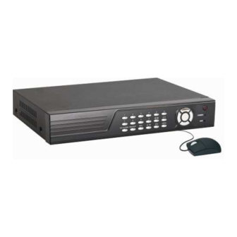
1. . . . YOUR DVR AT A GLANCE Product Overview Model 4 CH 8 CH 16 CH Video Format PAL/NTSC Video Compression H.264 Baseline Compression Video Input / BNC: 16 IN / 1 OUT / BNC: 4 IN / 1 OUT BNC: 8 IN / 1 OUT Output 1 SPOT / 1 HDMI... -
Page 10: Contents Of The Box
phone*. The video may be stored at a remote location for safety. (*Some limitations apply to web- and phone-based features, please see the related sections for detailed description.) Please get acquainted with the parts and accessories as well as the ways to use the appliance as described in this instruction manual. - Page 11 buttons Use arrow buttons to move among the menu items. Press Enter ( ) to confirm your choice. On live view the [ ] button is used as PTZ control key. Power LED, Record LED, Net LED LED lights indicate your connection to the power supply, recording status and net status. These buttons have the following functions: Menu ( ): access tool bar / hide tool bar / exit menu / exit sub menu.
-
Page 12: Back Panel (Please Take Actual Machine Model As Quasi)
3.2 Back Panel (please take actual machine model as quasi) Art. SDVR194B Art. SDVR004A Art. SDVR198B Art. SDVR196B 1. USB connectors Use these USB ports to connect the mouse and backup devices (flash drive, DVD recorder). Note: for some machine model USB port is on the lateral panel or on the front panel. - Page 13 5. Video Output Connector Video output for connecting monitor or TV, BNC (1Vp-p, 75 ) 6. VGA Connector For connecting VGA/LCD monitor 7. Ethernet Connector RJ-45 10/100 Base-T Ethernet network 8. Alarm Input Connectors ( ) (optional) 4/8ch: ALARM IN 1-4, 16ch: ALARM IN 1-16 For connecting to external sensor device Each alarm has one input pin on the terminal block of the rear panel.
-
Page 14: Remote Control
3.3 Remote Control In device operation, the enter key on the remote control or the front panel has the same function as a mouse left click. The buttons on the remote control correspond 1-1 with the buttons on the front panel. 1 Stop ( ): stop playback ■... -
Page 15: Mouse Control
3.4 Mouse Control You can use a mouse to operate the DVR as well. The mouse operates just like a mouse on a Windows PC. Please connect the mouse to the USB connector in the back panel and please note that you can hot-plug the mouse. -
Page 16: Hardware Installation
3.5 Hardware Installation It is recommended that the installations described below are carried out by qualified personnel. 3.5.1 Basic Connections Cameras Connect each of the cameras’ outputs to the video input socket in the rear panel of the DVR using appropriate cables. The video input interface is a standard BNC connector, 1Vp-p, 75 . -
Page 17: Installing Hard Disk Drive
3.5.2 Installing Hard Disk Drive Before you can record onto your HDD, it should be formatted by the DVR system, because standard PC formatting is not compatible. It can be done in the Maintenance Tab of the Tool Bar Main Menu. Please refer to Section 5.2.5 for the detailed description of this process. -
Page 18: Ptz Control Connections (Optional)
3.5.3 PTZ Control Connections (optional) Connect the PTZ control jacks to the corresponding RS485 A and B interfaces on the rear panel. For detailed description of PTZ protocols, baud rates and IDs please refer to the setup section in the PTZ manual. 4. -
Page 19: The Main Screen
4.1 The Main Screen The standard layout is four (nine or sixteen, depending on the device) windows evenly distributed over the screen. From the main screen you can access menu options and switch among channel views, displaying either all channel feeds simultaneously or bringing forth a full-screen view of a selected channel. -
Page 20: Tool Bar (Please Take Actual Machine Model As Quasi)
double-click right key of mouse on live view to display tool bar, it will appear the login window if the password is enabled. You can login from the LOGIN window as shown as previous fig. Select user name and user password via numeric keyboard. -
Page 21: Tool Bar Menu Options
(depending on devise). AUTO SEQUENCE: click “AUTO SEQUENCE” on the tool bar to enable auto sequencing, the channels with images will be in sequence: channel 1-channel 2-channel 3-channel 4-channel 1…… (4-CH DVR) / channel 1-channel 2-channel 3-channel 4-channel 5-channel 6-channel 7-channel 8-channel 1…… (8-CH DVR) /channel 1-channel 2-channel 3-channel 4-……-channel 14-channel 15-channel 16-channel 1……... - Page 22 into the setting interface; Or press the [►l l] button to enter into the setting interface. There are two methods of searching for recordings. Method 1: playback by date Date input: adjust the checking date and time and press【Enter】to input the number directly to adjust the year, month, date.
- Page 23 2. After moving the cursor up or down and selecting the files, left click to enter into playback interface. It will playback a single channel in full screen. 3. If the [RECORD TIME] section is marked as “ON” under the [VIDEO DISPLAY]section, it will show the date/time when playing back recorded file.
-
Page 24: Video Backup
Playback Control In the playback mode you can see the playback control panel as well as the date and time of the played file. Options for the playback control panel are described below: Fast rewind, the available speeds are 2x, 4x, 8x, 16x, 32x and 64x. Slow forward, the available speeds are 1/2x, 1/4x and 1/8x. -
Page 25: Playing Backed Up Video On Your Pc
Press 【Enter】 to confirm your selection. A checkmark “√” will appear at the end of the filename after you make your selection. Press【Enter】again and the “√”will disappear, thus cancelling your selection. You can start exporting the selected recording files by pressing【Backup】. Note: 1. -
Page 26: Ptz Control (Optional)
3) Click “ ” to capture a still picture. Click “ ” to enter into the “Settings” menu interface to set up the path for saving captured images. Click [Browser] to change the path for captured images. For example, select the folder “Desktop” and click [OK] to save the path. 4)Right click to open the shortcut menu window. - Page 27 A. Connection 1) Connect the control line of the speed dome camera to the RS-485 interface of the DVR. Make sure that A and B are matching. 2) Connect the video line of the speed dome camera to video input of DVR. 3) Activate the speed dome camera.
-
Page 28: Channel Status Display
<Menu CTRL> calls the menu of the high-speed dome after starting. After entering into the menu of high-speed dome, use [IRIS+] to confirm and use [IRIS-] to cancel. Left click to move the cursor up or down. Note: operating functions need to be supported by head end equipment and matched with the protocol. -
Page 29: Menu Options
5.1.1 Menu Options In order to modify/adjust system configuration, you need to enter the System Menu by pressing the Setting Page button in the Tool Menu. You will see the dialog window with settings for all systems and options available in your DVR. The settings are subdivided into 5 subsections, each with its own tab: Record, Video, System, Network, Alarm and PTZ (optional). -
Page 30: System
Several tabs have options that are positioned on more than one window, and you can navigate between them by pressing the “ ” button. 5.2 System Move the cursor to select “SYSTEM” (the icon will be highlighted when selected) and press 【ENTER】to enter into the system setup interface. -
Page 31: User Management
DST: Daylight Saving Time. “On” means DST is enabled. You can setup the start time and end time of DST. Note: you must press to save after you modify the time and date, your modifications will not be saved if you exit directly. 5.2.4 User Management Click [System settings →System →... - Page 32 REMOTE PERMISSION: it is a very important function for remote operation. Administrator can set every user’s remote permission, such as: PTZ Control, Record/Capture, Playback/Download, Setting, Mute On/Mute Off. VIEW PERMISSION: it is a very important function to set different view permission for different user.
-
Page 33: Hdd
After the password verification is set up (marked with “ON”) you can setup seven user password as well as an administrator password. If password function is enabled, you have to input password before logging in. Note: when password is enabled, you should login system as admin to manage user. -
Page 34: Maintenance
5.2.7 Maintenance Click [System settings → System → Maintenance] to enter [Maintenance] menu. SYSTEM UPDATE: create a new root directory called “dvrupgrade” on a thumb driver, copy the update file to it and then insert it into USB port. Press [Enter] to upgrade the firmware and it will display the process of the system upgrade. -
Page 35: Record
5.3.2 Record “ENABLE” indicates that the channel is enabled for recording. 5.3.3 Bit-rate There are three options: GOOD, NORMAL and LOW, corresponding to HIGHEST, HIGH and NORMAL data stream standard. The bit rate of each channel for recording can be adjusted independently. -
Page 36: Video
SCHEDULE: this setup function allows you to create a schedule for recording tasks throughout the week, so that only certain selected events are actually recorded on the HDD. For example, you may set up the system to record non-stop throughout the business hours, making it an alarm-triggered recoding at lunch time (that means no recording will be performed unless an alarm event happens), night time being set to motion detection recording with certain hours made more secure with the combined alarm and motion detection triggered recording,... -
Page 37: Channel
5.4.1 Channel You can select one channel to set up. 5.4.2 Name User can modify the name of the camera for each channel. Please note that the name of each channel supports up to nine character or four Chinese characters. 5.4.3 Position Name location is optional. -
Page 38: Margin
5.4.8 Margin Click [System settings →Video → Margin] to enter [Video margin setup] menu. You can move the entire video screen up, down, left and right using this option. 5.4.9 Video Setup Click [System settings →Video → Video Setup] to enter [Video Setup] menu. VGA: options include 1024x768 (VGA) and 1280x1024 (VGA) resolutions. -
Page 39: Ddns Setup
MEDIA PORT: transfers video data between client and device. WEB PORT: sets up the port of IE browser via HTTP. The default number for the WEB port is 8090 but model dependent. SETUP PORT: this port is fixed and you can’t modify it, the value is 8000. DNS: press [Enter] and input numbers for the DNS. -
Page 40: Email Setup
DDNS: options are “ON/OFF”. If there is a DDNS server, select “ON”. SERVER: there are some options: 3322, dyndns, perfecteyes... HOST NAME: input the name of the host server. USER NAME: input the name of the user. PASSWORD: input the password. 5.5.3 Email Setup Move the cursor to EMAIL and press [Enter] to enter the interface. -
Page 41: Ip Access Setup
SERVER PORT: mobile monitoring port. Input the correct mobile port and press [ ] to confirm. The setting range is between 1024 and 65535. The default value is 10510. NETWORK TYPE: select from different mobile network including 3G, 2.5G, 2.75G and WIFI; press [ ] to choose a new network. -
Page 42: Duration
“OFF”, “5s” , “ 10s” , “ 30s” and “60s” . If you choose “OFF”, the alarm will not be triggered in any case. 5.6.2 DURATION This function sets the duration of the recording time after alarm recording is activated. Options include “30s, 1min, 2min and 5min”. -
Page 43: Motion Detection
I/O ALARM:eEach channel corresponds to an I/O status, which means when an alarm is triggered, it will activate the corresponding channel to start alarm recording. N.O.: Normally Open type. It means that in the normal state, the sensor device is kept under constant low voltage. -
Page 44: Ptz (Optional)
Each channel has a corresponding regional motion detecting setting, move the cursor to corresponding 【 setting】 and press 【 Enter】 to enter regional setting interface. The blue area means motion detection is activated, transparent block means motion detection is not activated. Press the direction key on remote control to move the cursor along the small pane: position of cursor is indicated by green frame. -
Page 45: Data Bit
5.7.4 PTZ Data Bit Options include 5, 6, 7 and 8.The default setting for DATA BIT is 8. 5.7.5 PTZ Stop Bit Options include 1 and 2. The default setting is 1. 5.7.6 PTZ Parity Options include None, Odd, Even, Mark and Space. The default setting is none. 5.7.7 PTZ Address Select the PTZ device ID. -
Page 46: Connection Setting
(3) Click “Customization level” to enter into the security setting. Set the ActiveX control and pluggable unit. Select the following options √ ActiveX control auto-prompting √ Run the script of the ActiveX control which is marked to be that can safely implement the script. - Page 47 connecting and setting method for the local area network. Step 1: right click on “Network neighborhood” and click “Attribute” in the ejected menu to open the “Network connection”. Step 2: double click to open “Local connection”. Step 3: click “Attribute”. Step 4: double click “Internet protocol (TCP/IP)”.
-
Page 48: Control Download And Installation
Step 5: examine the IP address, subnet mask and default gateway on the PC. Step 6: set the corresponding IP address, subnet mask, and default gateway on the DVR (refer to 5.5.5 Network Setup). If the subnet mask and default gateway on DVR are the same with those of the PC, then the IP address must be in the same network section but cannot be the same with the used one. -
Page 49: Operation Interface
Select English interface from the top left side. Input correct password if password is enabled to enter the system. The password is the same as the one set in DVR. USER ID: input user name. The administrator has all authorities, but common user has been limited authorities by administrator. -
Page 50: Other Operation
Capture picture, save in local disk, system save default path is “c:\DVR\BACKUP\”. Quick-start to record video on all channels. The left upper corner of each channel has normal recording video symbol Click icon to switch between single screen /quad /nine /16 split /full screen... -
Page 51: Instruction Of Toolbar
The highlighted date indicates that video was recorded on that day. Click on a date to search the recording file list of that day. For example, the above fig. shows that June, 12th, 13 have recorded video when it shows on bold, and current search date is June 12 Select channel and type at the bottom of the calendar. - Page 52 B. Record Setting Click [Record Setting] to enter into the menu interface, user can select “on/off” for each channel, and adjust recording parameters (audio, pack time, REC mode and REC schedule) remotely via net-viewer. C. Alarm Setting Click [Alarm Setting]-[Device Alarm] to enter into setup interface. Click [Alarm Setting]-[Channel Alarm] to enter into setup interface.
- Page 53 D. PTZ Setting Click [PTZ Setting] to access setup interface. User can setup PTZ parameters remotely using the same methods as in the local DVR setup. E. Network Setting Click [Network Setting] - [Network] to enter setup interface. The menu allows user to set a lower bandwidth for Internet video transmission.
- Page 54 Click [Network Setting] - [Email] to enter setup interface. User can setup network parameters using the same methods as in the local DVR setup. F. System Setting Click [Advanced Setting] - [System Setting] to enter setup interface. The menu allows user to set daylight saving time.
- Page 55 G. System info Click [System info] - [Version info] to enter setup interface. Here user can check the device’s ID and software version. Click [System info] - [HDD info] to enter setup interface. Here user can check HDD state, total size of HDD and free size of HDD.
- Page 56 H. . . . Remote upgrade Click [Remote upgrade] to enter remote upgrade interface. Then click remote upgrade button in the middle. H. User Manager Click [User Manager] - [ADD or DEL] to enter setup interface. This interface could only been seen by administrator when password is available.
-
Page 57: Local Setting
Click [User Manager] - [Modify password or PRI] to enter setup interface. This interface could only be seen by administrator when password is available. Administrator can change password, local authority and remote authority. 6.5.7 Local Setting Click [Local Setting] to enter setup interface. User can setup the save path for local setting. “Record save path”... -
Page 58: Logout
6.5.8 Logout Click [Logout] to log out of the system. 7. Wap Connection The digital video recorder can also be remotely accessed by using a web browser installed on a mobile phone that support xHTML and MJPEG file format and has screen resolution at 320x240 or above. -
Page 59: Mobile Phone Support
5. Now you can get picture from the monitor channel. The picture will refresh in several seconds automatically if you had chosen a refresh time in setting page. While you have chosen manual as refresh mode, it won’t refresh automatically until you click “refresh”. The monitor channel, the picture size and refresh time is decided by setting page. -
Page 60: Symbian S60 3Rd And 5 Phone
In the following screen, input the User Name, Password, Server (IP address for your DVR) and Port (default 10510). Next, choose the channel Count for streaming data from the drop-down menu and choose the Default Channel when connecting. Choose a Record Name for your favorite files. - Page 61 Please see a sample installation process shown below: After the installation is complete, please locate the Mobile Eye icon “ ” in the list of applications on your mobile phone. In order to start working with the CCTV feed on your Symbian mobile phone, you will have to configure the program by entering the preferred network access point, IP address of the DVR, mobile phone port, username and password.
- Page 62 In the Setting screen, enter the following data: Select Default Point: choose the network through which you connect to the Internet. The options are: “None”, “WAP over GPRS”, and mobile service providers operating in your country. If you choose “None”, then after pressing the button you will be offered a list of available networks to choose from.
- Page 63 Control buttons: Select channels. If your system supports 8-channels, use functional button switch between channel buttons 1-4 and 5-8. PTZ camera direction controls PTZ camera Zoom, Focus and Iris controls Functional buttons: When highlighting these buttons, the name of the corresponding function will be displayed in the status information line (the first tag name).
- Page 64 List of Symbian Supported Mobile Phones Please review the list of Symbian mobile phones tested for compatibility with the remote access to DVR. LG-KT610 Nokia N71 LG KS10 Nokia N73 LG-KT615 Nokia N75 Nokia 3250 Nokia N76 Nokia 5320 XpressMusic Nokia N77 Nokia 5500 Sport Nokia N78...
-
Page 65: Apple Iphone
8.3 Apple iPhone 1) Installation Open iPhone App store “ ” as follows: Fig 1 ① Click“ ”button and search for “MobileEye” or “MobileEye+”. Are free applications. Fig 2 ② Click “ ” and you will see following screen. - Page 66 Fig 3 ③ Click “ ” as shown in Fig 3. It will display the screen shown in Fig 4. Click the “install” button shown in Fig 4 “ ” and it will display the screen shown in Fig 5. Input your Apple account password, then click “...
- Page 67 Fig 6 “ ”Loading: indicates that the “MobileEye” software is downloading ……. When the ”status, the MobileEye software has finished installing. “ ” process bar display“ After installing “MobileEye”, the iphone screen will display the screen shown in Fig7. Fig 7 2) How to use MobileEye ⑴...
- Page 68 Fig 8 (2) Press the setting button show as above. The screen will look like the one shown in Fig 9. Fig 9 (3) You have two ways to enable the view screen. a.When you press the “Server Access” button, it will display like Fig 10.
- Page 69 After you enter the Setting menu, the window below is shown: ①Server ID: Device ID number ②User ID:Admin ③Password: The Admin password of DVR b. When you press the “Direct Access”, it will display like Fig 11. After you enter the Setting menu, the window below is shown: ①Server IP: DVR Internet address.
-
Page 70: Android Mobile
①PTZ arrow control(up down left right) ②PTZ lens control(zoom+, zoom-), (focus+, focus-), (iris+, iris-). ③Select the live view channel. ④Shortcut key, including pause, capture, full screen, next channel grouping and settings. ⑤Exit 8.4 Android Mobile 1). Install the program 1. Copy the setup software “Mobile Eye-Android.apk” or “Mobile Eye+-Android.apk”to your computer. - Page 71 Select option “Application Installer” and click the left mouse, then the user can find the setup file; install “Mobile Eye-Android.apk” on your mobile telephone according to the following method.
- Page 72 Please ensure that if asked, you allow the application access to the internet. When application has finished installing, your phone may show the following screen.
- Page 73 2). System explanation Mobile Eye application mainly allows: live video surveillance, channel switching, full screen viewing, PTZ control, focus, and image capture, save as favorite and exit function. 2.1) System main interface After the installation, select the “Mobile Eye” icon in the application, see below picture: Below is displayed the main start page of the application: Switch channel...
- Page 74 2.2) System setting interface Press the [setting] button to access the parameters settings. You will need to use this for the first time you use the system and later if you want to change the parameters of the system. Save as favorite: save settings for future usage User name: the device ID which is set on DVR [phone surveillance] Password: the user password which is set on DVR [phone surveillance] Server: the public IP address or dynamic domain name of DVR...
- Page 75 See below for more details: :press this icon to connect to the DVR : press this icon to open the settings menu : change live view channel. :use the arrows to move the PTZ up, down, left and right. : these icons operate the zoom, focus and iris. :this function will capture the current viewed image.
-
Page 76: Troubleshooting
Troubleshooting This basic troubleshooting guide will help you identify general malfunctions and offer steps for quick resolution of such. If the failure or malfunction can't be solved by following these steps, please contact a qualified technician. 1. DVR is not working after starting. What happened? ? ? ? Check the adaptor input. - Page 77 6. What if there is no sound when monitoring? Check the sound box or speaker functions. Also check for possible short circuiting problems. Audio source may be connected to the video channel. You can click to full-screen to check. The hardware of DVR could be defective. 7.
-
Page 78: Appendix 1 Setting Up Internet Connections For Remote Access
Appendix 1 Setting up Internet Connections for Remote Access This section will explain the ways to connect your DVR to the internet using static and dynamic IP addresses. To connect to the internet, you will need to use a modem and a router. As a network device, your DVR should have its own address called an Internet Protocol (IP) address. -
Page 79: Appendix 3 List Of Compatible Portable Usb Dvd Recorders
Appendix 3 List of Compatible Portable USB DVD Recorders Please find below the list of tested portable USB DVD recorders found to be compatible with the DVR. If for backing up your data from the DVR, you wish to use a DVD recorder not found on this list, please test it for compatibility. - Page 80 5. Select “Allow” to download multiple file and the interface will show as follow. 6. Select “Continue” to continue installing extensions and the interface will show as follow. 7. Click “Install’ and the interface will show as follow. If it Note: if the web page still can not open, you can press the icon”...
-
Page 81: Appendix 6 How To Use Auto Id
8. Fill in your correct user name and password to login. Appendix 6 How to use Auto ID "Plug n play" Quick Guide 1.The ID number of the product has been set up in the factory .Click [tool bar]- [system setting]-[user],The screen will display user manager menu, and you will see the ID number. - Page 82 4. When the network is connected, input http://www.ipremoteview.com in the address field of the IE. Then input the ID of the DVR into the product number as below. 5. After the connection succeed. It will switch to the Web Application Manage page, as follow.
- Page 83 Note: please refer to the Section 6.4 Control Download and Installation for the operations thereafter. Via Don Arrigoni, 5 24020 Rovetta S. Lorenzo (Bergamo) http://www.comelitgroup.com e-mail:export.department@comelit.it...
Need help?
Do you have a question about the SDVR004A and is the answer not in the manual?
Questions and answers