
Subscribe to Our Youtube Channel
Related Manuals for ATV 4, 9, &16-ChannelTalon Triplex Color Multiplexers

Summary of Contents for ATV 4, 9, &16-ChannelTalon Triplex Color Multiplexers
- Page 1 4, 9, &16-Channel Talon Triplex Color Multiplexers Installation and Operating Instructions...
- Page 2 ISSUE 1 – MARCH 2003 LIMITATION OF LIABILITY THE INFORMATION IN THIS PUBLICATION IS BELIEVED TO BE ACCURATE IN ALL RESPECTS, HOWEVER, WE CANNOT ASSUME RESPONSIBILITY FOR ANY CONSEQUENCES RESULTING FROM THE USE THEREOF. THE INFORMATION CONTAINED HEREIN IS SUBJECT TO CHANGE WITHOUT NOTICE. REVISIONS OR NEW EDITIONS TO THIS PUBLICATION MAY BE ISSUED TO INCORPORATE SUCH CHANGES.
-
Page 3: Warnings And Cautions
WARNINGS AND CAUTIONS TO REDUCE THE RISK OF FIRE OR ELECTRIC SHOCK, DO NOT EXPOSE THIS PRODUCT TO RAIN OR MOISTURE. DO NOT INSERT ANY METALLIC OBJECTS THROUGH THE VENTILATION GRILLS OR OTHER OPENINGS ON THE EQUIPMENT. CAUTION EXPLANATION OF GRAPHICAL SYMBOLS The lightning flash with arrowhead symbol, within an equilateral triangle, is intended to alert the user to the presence of uninsulated “dangerous voltage”... -
Page 4: Fcc Compliance Statement
FCC COMPLIANCE STATEMENT FCC INFORMATION : THIS EQUIPMENT HAS BEEN TESTED AND FOUND TO COMPLY WITH THE LIMITS FOR A CLASS A DIGITAL DEVICE, PURSUANT TO PART 15 OF THE FCC RULES. THESE LIMITS ARE DESIGNED TO PROVIDE REASONABLE PROTECTION AGAINST HARMFUL INTERFERENCE WHEN THE EQUIPMENT IS OPERATED IN A COMMERCIAL ENVIRONMENT. - Page 5 IMPORTANT SAFEGUARDS READ AND RETAIN INSTRUCTIONS 10. LIGHTNING Read the instruction manual before operating the For protection of the equipment during a lightning storm equipment. Retain the manual for future reference. or when it is left unattended and unused for long periods of time, unplug the unit from the wall outlet.
- Page 6 (This page intentionally left blank.)
-
Page 7: Table Of Contents
TABLE OF CONTENTS INTRODUCTION ..........................1 Features ............................1 Technical Overview........................1 PRODUCT OVERVIEW........................3 Front Panel Buttons ........................3 DISPLAY..........................3 PIP ............................3 SEQUENCE..........................3 FREEZE........................... 3 ROTATE ..........................3 ZOOM ............................4 ACCEPT / CANCEL / ARROW Buttons.................. 4 PLAYBACK.......................... - Page 8 Setup Menu ..........................11 Time Date Setup........................12 Camera Access Setup......................13 Camera Title Setup........................ 14 Camera Sequence Setup ...................... 14 Alarm Setup ........................... 15 Alarm History List ........................21 Motion Detection Setup ......................24 Playback & Recording Setup ....................27 Camera Picture Adjustment ....................
-
Page 9: Introduction
CHAPTER 1 INTRODUCTION Features • Compatible with standard color cameras and other video sources • Switchable between NTSC and PAL • Able to decode tapes from many other brands of multiplexers • Multiple user-selectable formats for displaying camera images. • Multiple monitor outputs allow simultaneous multi-camera and full-screen viewing. - Page 10 The multiplexer plays back video tapes recorded with many other multiplexers. These include but are not limited to: Dedicated Micros, Robot, Kalatel, and Pelco. Multiplexers can be “daisy chained” and addressed and controlled by a single control panel. The multiplexer can also be addressed by a computer using either an RS-232 or RS-485 connection.
-
Page 11: Product Overview
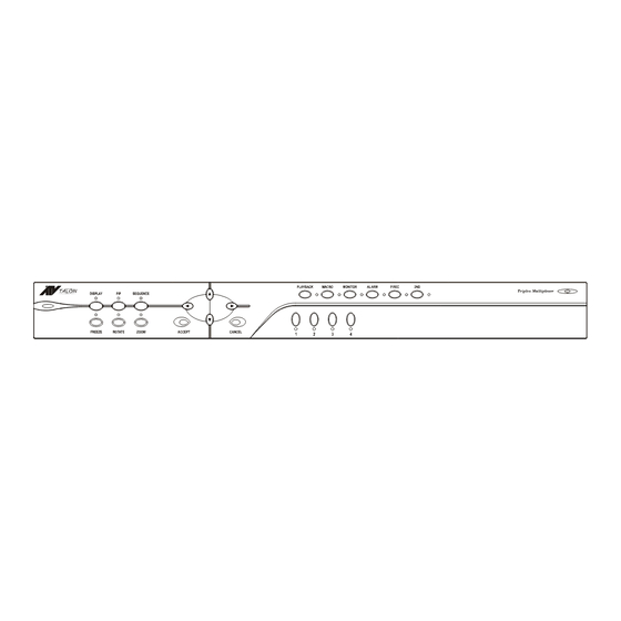
CHAPTER 2 PRODUCT OVERVIEW This manual is to be used for all three models of the Triplex Color Multiplexers. The features are the same with the exception of camera connection capability. This manual was written based on the 16-channel unit. Note that some screens or option are not available for the 9 or 4- channel units due to reduced camera connections. -
Page 12: Zoom
ZOOM The ZOOM function expands the selected portion of a full frame camera image in live mode. Pressing the ACCEPT button increases the magnification factor up to 32x. Pressing the CANCEL button decreases the magnification from the zoomed image down to the original image. -
Page 13: 2Nd
The 2ND button is used to reset alarms and select user defined modes. CAMERA 1 – 16 Buttons The Camera buttons are used to select cameras for viewing or as numbers in programming configurations. Back Panel Connections The connections on the back of the multiplexer are explained below. The only difference between the 4, 9, and 16-channel unit back panel connections are the number of camera inputs and outputs. -
Page 14: Rs-485 (In And Out)
RS-485 (IN and OUT) The RS-485 S-Video connectors are used for remote control operations. DC12V The DC12V connection is the main power supply input for the multiplexer. Setting for NTSC or PAL Operation Upon initial setup, the multiplexer should be set to the NTSC or PAL configuration. When changing the operation setting, all other unit settings return to the default configuration. -
Page 15: Installation
CHAPTER 3 INSTALLATION System Configuration The Triplex Multiplexer is only one part of a complete system that controls cameras, monitors, recording devices, alarm equipment, and other accessory items. The following figure illustrates the connections feeding off a 16-channel multiplexer for a complete security system solution. Camera Connections The multiplexer supports 4, 9 or 16 camera inputs depending on the model. -
Page 16: Connecting Recording Devices
Connecting Recording Devices The multiplexer has both BNC and S-VIDEO connections for use with a recording device such as a VCR or DVR (Digital Video Recorder). The figures below show examples of one VCR connected to the multiplexer for use in both recording and playback, and two VCRs being used to allow simultaneous recording and viewing of video. -
Page 17: Alarm Connections
Alarm Connections The 50-pin ALARM IN/OUT connector features 16 alarm inputs, 16 alarm outputs, RS-232 connections, VCR trigger pulse, and various alarm settings. A sub-board is supplied with the multiplexer to simplify connections. The board connects to the 50-pin connector via a ribbon cable. -
Page 18: Menu Setup And Operation
CHAPTER 4 MENU SETUP AND OPERATION Accessing the TOP and BOTTOM Menus The multiplexers use On-Screen Display (OSD) menus. Navigation through the menus is possible through the front panel buttons, an optional mouse attached to the unit, or through a remote control device. -
Page 19: Live
Switches to a 9-camera display on the screen (not available on 4-ch model) Switches to a 16-camera display on the screen (not available on 4 or 9-ch models) User Def The four User Defined options switch the view on the screen to the user- selected options stored in four different settings. -
Page 20: Time Date Setup
Time Date Setup The Time Date Setup screen is used to format the multiplexer’s time and date settings and to setup the daylight savings time option. The NEXT option at the bottom of the screen leads to the Daylight Savings Time setup screen. The EXIT option saves the settings and exits the Time &... -
Page 21: Camera Access Setup
Daylight Savings: If you are in an area that does not have Daylight Savings Time, set this option to OFF. When you set this to ON, you must set the start and stop dates and times. Start: Set the month and day (date) for the beginning of daylight savings time in your area. Stop: Set the month and day (date) for the ending of daylight savings time in your area. -
Page 22: Camera Title Setup
Camera Title Setup The Camera Title Setup screen allows the user to enter a title for each camera. The maximum length of the title is 24 characters, including spaces. To set the camera title, select the desired camera so the image appears in the display window. -
Page 23: Alarm Setup
To change the camera or dwell setting, use the arrow keys on the front panel (or the mouse) to move the cursor to the option to be changed. Use the ACCEPT button to decrease and the CANCEL button to increase the number selection. The Page Dwell Time is the length of time each group of cameras will display. - Page 24 Alarm I/O Setup The Alarm In setting options are NO (Normally Open), NC (Normally Closed), or OFF. The Alarm Out setting options are AH (Active High) or AL (Active Low) TTL output. The Exit option saves the changes and returns to the Alarm Setup menu. Alarm Action Setup There are two screens for the Alarm Action Setup as shown below.
- Page 25 Spot Monitor 1 – 4: When set to ON, the Spot Monitor displays the camera with an alarm condition. When there are multiple alarms, cameras with alarms display sequentially. When set to OFF, the Spot Monitor’s display does not change during an alarm condition.
- Page 26 Motion Action Setup There are two screens for the Motion Action Setup as shown below. The Next and Back buttons toggle between the two screens. The Exit button saves the settings and returns to the main Alarm Setup menu. Buzzer: When set to ON, the multiplexer’s internal buzzer sounds upon a motion alarm condition.
- Page 27 Video Loss Action Setup The Video Loss Action Setup screen allows the user to set up the action the multiplexer takes when there is a video loss condition. Buzzer: When set to ON, the multiplexer’s internal buzzer sounds upon a video loss condition.
- Page 28 Buzzer: When set to ON, the multiplexer’s internal buzzer sounds upon a manual alarm condition. Alarm Screen: When set to ON, the screen display changes to the one defined in the Alarm Screen Format menu during a manual alarm condition. Network Relay: When set to ON, the multiplexer sends the alarm information to an external relay box via the network during a manual alarm condition.
-
Page 29: Alarm History List
PC. The diagram on the following page shows the connections The print feature also requires a “Download.exe” program to be loaded onto the PC. NOTE: Contact ATV at 888-288-7644 or go to their website at: www.atvideo.com 1. Implement the “Download.exe” file and click the icon named “Print Program”. - Page 30 PERSONNAL COMPUTER D-SUN CONNECTOR (9-PIN) After connecting the multiplexer to the PC and downloading the “exe” file from ATV’s website, perform the following steps: 1. Execute the “Download.exe” file. 2. When the screen shown below on the left appears, test the connection from the PC to the multiplexer by checking the “Enter Key”...
- Page 31 Print Program Window Alarm History Window...
-
Page 32: Motion Detection Setup
Motion Detection Setup The Motion Detection Setup menu is used to set the motion detection feature ON or OFF. Three additional submenu’s provide further setting options for the index, scheduling, and sensor options. The All Motion Detection option is a global switch that turns the motion detection function ON or OFF for all cameras. - Page 33 The Motion Detection Index List displays the priorities assigned to the cameras. This screen is for viewing only and does not allow editing options. Motion Detection Schedule Setup The multiplexer can be set to detect or ignore motion based on a schedule. This feature allows the motion detection to ignore certain cameras with high activity during normal business hours yet detect generate an alarm condition when the office is closed and activity needs to be monitored.
- Page 34 On / Off: This turns the motion detection option for the selected mode either ON or OFF. Update / Master: When set to the Update option, the multiplexer compares the current field with the previous field. When set to the Master option, the multiplexer compares a master image to continuous video.
-
Page 35: Playback & Recording Setup
For Normal Motion Detection: • Set: Highlights the grid area. (A click of the mouse on this option produces no action.) • Dot / Line / All: Determines how many targets will be turned ON or OFF. DOT = single target, LINE = row of targets, ALL = all of the targets. •... - Page 36 VCR System Setup The VCR System Setup screen provides optional settings when connecting a VCR with the multiplexer. VCR Input: A VCR connects to the multiplexer using the BNC or SVHS connections. Set the VCR Input option to the type of connection used. External Trigger: Set to OFF when not using the VCR synchronizing trigger pulse.
-
Page 37: Camera Picture Adjustment
Recording Index Setup Normally the multiplexer gives the same priority to all cameras. However, you can set the recording index to give higher priority to specific cameras. The screen shown above is used to set the priority of each camera for recording (up to 128 index positions). -
Page 38: Macro Setup
Contrast: The contrast adjustment range is –100 to +153. Brightness: The brightness adjustment range is –127 to +126. Tint: The tint adjustment range is –127 to +126. (Not available for PAL operation.) Color: The color adjustment range is –103 to +114. Sharpness: The sharpness setting ranges from Nominal to 5. -
Page 39: Unit Setup
Macro Schedule Setup The Macro Schedule feature allows the user to schedule up to 20 events that use a recorded macro. Select the Event option (01 through 20) and set the ON/OFF option to ON to activate it. Select the Macro number (01 through 16) to correspond to the event, then set the hour, minute, and day(s) of the week the event is to occur. -
Page 40: Password Setup
Mouse Setup: The sensitivity of the mouse operation can be changed using the Mouse Setup option. The range is: MIN (-009) to MAX (+009). Master / Slave: When installed as part of a network, this setting determines whether the unit is a master or slave unit in the network. Network Type: The multiplexer can be set to RS-232, RS-422, or RS-485 when connected to a network. -
Page 41: Pop-Up Menu
Select CANCEL to exit the Administrator Password screen at any time and return to a live display. User Change Password: When set to ON, a password will be required to make screen configuration changes or to access items on the Pop-Up menu. ADMIN / User 1 –... -
Page 42: Vcr Camera Change
VCR Camera Change The VCR Camera Change option on the Pop Up menu is only available when the unit is in the VCR Playback mode. Like the Live Camera Change, the VCR Camera Change option allows the user to assign any camera to a cameo view. The following screen shows options for the 16 channel unit. -
Page 43: Priority
Priority When Priority is set to ON for a camera, it will display in real time while the refresh rate of the remaining displayed cameras will slow down. Histogram HEQ1 to 4 - Each Histogram Equalizer button increases image contrast. HEQ1 has the weakest equalization and HEQ4 has the strongest. -
Page 44: Utilities
Utilities The Utilities option on the Pop Up menu brings up another Pop Up menu with additional options. User Screen Change The User Screen Change option has four user defined display formats that can be setup in various viewing formats. Selecting the UserDef1 – UserDef4 option button brings up a screen format window. - Page 45 OSD Change The OSD Setup screen allows the user to select the text that is to appear on the screen and to select the color. Border Line is the border around the images. “Lv” stands for Live. “Pb” stands for Playback. The Camera Number, Camera Title, and Time & Date text can be set to On or Off.
- Page 46 The multiplexer can play back tapes that were recorded using multiplexers designed by different manufacturers. The Playback Format option allows the user to select from the settings: OWN, ATV, Dedicated Micros, Robot (Sensormatic), Pelco, and Kalatel (Impac). PB Picture Adjust The PB Picture Adjust option only appears on the Utilities Pop Up menu when the multiplexer is in the VCR Playback mode.
-
Page 47: Appendix A - Troubleshooting
APPENDIX A - TROUBLESHOOTING Problem Check No Video (black screen) Check power connections No Video (one camera) Check camera power and coaxial cable No Video (jumbled colors) Make certain the multiplexer is set correctly for your system (NTSC or PAL) Fuzzy Image (one camera) Check camera focus Bad video (one camera) -
Page 48: Appendix B - Remote Control Operation
APPENDIX B - REMOTE CONTROL OPERATION RS-232 Remote Control Interface The multiplexer has a built-in RS-232 serial interface which supports remote control operation through simple ASCII commands. The commands provide access to the front panel button operations just like the IR remote control. The multiplexer serial interface is fixed at 9600 baud, 8-bit, 1 stop bit, and no parity. -
Page 49: Time / Date Commands
– Panic recorder buzzer on/off k : 0 = off, 1 = on LPBO n VCR playback options n : 0 = OWN, 1 = ATV, 2 = DM, 3 = ROBOT, 4 = PELCO 5 = KALATEL Camera Commands LBLE n Camera label enable. -
Page 50: Other Commands
ABUZ n,m Alarm buzzer on/off n : 0 = External alarm, 1 = Manual alarm, 2 = Vloss alarm, 3 = Motion alarm m : 0 = off, 1 = on ASCR n,m Alarm screen on/off n : 0 = External alarm, 1 = Manual alarm, 2 = Vloss alarm, 3 = Motion alarm m : 0 = off, 1 = on AMSG n,m... -
Page 51: Appendix C - Factory Default Settings
APPENDIX C - FACTORY DEFAULT SETTINGS Setting Default Configuration Date Format US (MM/DD/YY) Time Format 24-hour Clock Source Internal clock Daylight Savings Camera Access All cameras ON Cameras to Record All cameras ON Page Dwell Time 3 seconds Sequence Dwell Time 3 seconds Alarm Reset Button Alarm Screen Format... - Page 52 Setting Default Configuration Motion Alarm Link Vloss Buzzer Vloss Screen Vloss Network Relay Vloss Message Latch Vloss Spot Monitor Output Vloss Hold Time 20 seconds Manual Alarm Buzzer Manual Alarm Screen Manual Alarm Network Relay Manual Alarm Message Latch Manual Alarm Recording INT (Interleaving) Manual Alarm Spot Monitor Output Manual Alarm Hold Time...
- Page 53 Setting Default Configuration Camera Brightness Camera Color Camera Tint Language English Mouse Key Lock Camera Number Offset Mouse Setup Master / Slave Slave Network Type RS-485 Baud Rate 9600 Unit Address Protocol Setup Menu Password User Change Password Password Code ADMIN –...
-
Page 54: Appendix D - Specifications
APPENDIX D - SPECIFICATIONS Operating Defaults Display Format 4x4 multi-screen format Operation Mode Live Video Format NTSC / PAL Standard Video Level Camera Inputs / Outputs 1.0V p-p, 75 ohms Loop through Output 1.0V p-p, 75 ohms VCR Input: Composite 1.0V p-p, 75 ohms VCR Input: S-Video Luma 1.0V p-p, 75 ohms... - Page 55 Dimensions Unit size (D x W x H) 12.2” x 17” x 1.73” 310mm x 432mm x 44mm Unit Weight 5.31 Ibs (2.4 Kgs) Operating Environment Ambient Temperature 32° to 95° F (0° to 35° C) Ambient Humidity 10% to 90% non-condensing...
- Page 56 Advanced Technology Video, Inc. 1601 WALLACE DRIVE STE 102 CARROLLTON, TX 75006 Tel: 425-885-7000 Toll Free: 888-288-7644 Fax: 425-881-7014 4, 9, &16-Channel www.atvideo.com Talon Triplex Color Multiplexers 50301591B...
Need help?
Do you have a question about the 4, 9, &16-ChannelTalon Triplex Color Multiplexers and is the answer not in the manual?
Questions and answers