Table of Contents
Advertisement
Quick Links
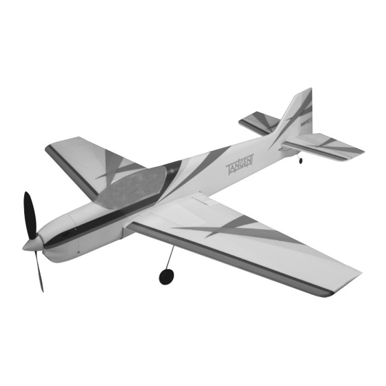
Electric-Powered Park-Flyer Pattern Plane
INSTRUCTIONS FOR FINAL ASSEMBLY
Specifications:
The Wattage Tangent EP is distributed exclusively by
Wing Span: 31.5 Inches
Global Hobby Distributors 18480 Bandilier Circle,
Wing Area: 183 Square Inches
Fountain Valley, CA 92708
Length: 31 Inches
Weight RTF: 15 - 17 Ounces
Functions: Ailerons, Elevator, Rudder and Throttle
Power: 370 Motor w/3.67:1 Gear Box & 7.5 x 5 Propeller
Radio: 4 Channel Micro w/3 Servos & 15 AMP ESC
All contents copyright © 2002, Global Hobby
Distributors Version V2.0 May 2002
Kit Product Number 128417
1
Visit our website at http://watt-age.globalhobby.com for information on other Wattage products
Advertisement
Table of Contents

Related Manuals for WattAge Tangent


Summary of Contents for WattAge Tangent
-
Page 1: Specifications
Power: 370 Motor w/3.67:1 Gear Box & 7.5 x 5 Propeller Radio: 4 Channel Micro w/3 Servos & 15 AMP ESC All contents copyright © 2002, Global Hobby Distributors Version V2.0 May 2002 Kit Product Number 128417 Visit our website at http://watt-age.globalhobby.com for information on other Wattage products... -
Page 2: Table Of Contents
In no case shall Wattage's liability exceed the original cost of the purchased kit. In that Wattage has no control over the final assembly or material used for final assembly, no liability shall be assumed for any damage resulting from the use by the user of the final user-assembled product. -
Page 3: Introduction
INTRODUCTION Thank you for purchasing the new Wattage Tangent EP pattern plane. Before completing the final assembly of your new airplane, please carefully read through this instruction manual in its entirety. Doing so will ensure your success the first time around! Wattage Tangent EP Features: 370 Size Motor w/3.67:1 Gear Box and 7.5 x 5 Nylon Propeller... -
Page 4: Section 1: Our Recommendations
SECTION 1: OUR RECOMMENDATIONS This section describes the items you will need to purchase for your new Tangent EP. These suggestions are not set in stone, but they should provide you with a good starting point. IMPORTANT When choosing accessories for your Tangent EP, such as servos, ESC, and receiver, it's very important to take the weight of these items into consideration. -
Page 5: Section 2: Tools And Supplies Required
3M 3/4" Wide Clear Plastic Tape - Available at Most Hardware Stores IMPORTANT The part numbers listed for the Hitec receiver, Cirrus servos and Wattage ESC are compatible with Hitec and JR (receiver is compatible with Hitec only) radio control systems. These items are also available with connectors that are compatible with Futaba and Airtronics radio control systems. -
Page 6: Section 3: Kit Contents
SECTION 3: KIT CONTENTS We have organized the parts as they come out of the box for easier identification during assembly. Before you begin assembly, group the parts like we list them below. This will ensure that you have all of the parts before you begin assembly and it will also help you become familiar with each part. -
Page 7: Section 4: Replacement Parts
WARNING The Tangent EP includes a foam wing, stabilizer and rudder. It is very important that you use no solvents, Cyanoacrylate (C/A) glue, or paint that can damage foam. If any of these chemicals comes in contact with the foam parts, the parts will be destroyed and will not be covered under warranty. -
Page 8: Section 6: Wing Assembly And Mounting
SECTION 6: WING ASSEMBLY & MOUNTING YOU'LL NEED THE FOLLOWING PARTS: (1) 3mm Plywood Plate - Rounded w/Cutout (1) Fiberglass Fuselage (1) Left & Right Wing Panels (3) 3mm x 15mmm x 20mm Plywood Plates (2) 180mm Balsa Support Rails (1) Center Section Reinforcement Board (1) 30mm Fiberglass Dowel (1) Trailing Edge Reinforcement Board... - Page 9 Trim the ends of the tape flush with the wing using a modeling knife. Using the same technique, apply a strip of clear plastic tape over the center section joint on the bottom of the wing. Visit our website at http://watt-age.globalhobby.com for information on other Wattage products...
- Page 10 Apply two long strips of clear plastic tape to the bottom of the wing. Apply the strips of tape down the middle of the wing, perpendicular to the center section joint, from wing tip to wing tip. These strips of tape help strengthen the wing. Do not omit this procedure.
- Page 11 1/8" in front of the trailing edge reinforcement board. IMPORTANT It's very important to the integrity of the wing that the reinforcement board be adhered to the wing along its entire surface. Visit our website at http://watt-age.globalhobby.com for information on other Wattage products...
- Page 12 Step 5: Installing the Battery Tray & Belly Pan Support Rails Using a ruler and a pencil, measure back 3/16" from the leading edge of the wing, at the centerline, and draw a mark. Using 220 grit sandpaper with a sanding block, carefully sand the front of the wing straight across, back to the mark you drew.
- Page 13 U-shaped cutout in the plywood plate. IMPORTANT Make sure to drill the hole straight and not at an angle. Visit our website at http://watt-age.globalhobby.com for information on other Wattage products...
- Page 14 Test-fit the 30mm long fiberglass dowel into the hole. The dowel should be pushed into the hole deep enough so that 3/8" of it is beyond the leading edge. It is also important that the dowel be straight and not angled up, down or side to side. When satisfied with the alignment, glue the dowel into place using a generous amount of 5 minute epoxy.
- Page 15 When satisfied with the fit, mix a small quantity of 5 minute epoxy and use it to glue the plywood plate into place, being careful not to get any epoxy between the wing and/or plywood plate and the fuselage. Visit our website at http://watt-age.globalhobby.com for information on other Wattage products...
- Page 16 After the epoxy has cured, set the belly pan onto the wing and push it down firmly into place. Check the fit of the belly pan. To do this, align both the front and back of the belly pan with the sides and bottom of the fuselage.
-
Page 17: Section 7: Stabilizer Assembly And Installation
Remove the protective backing from the strip of white self-adhesive tape and apply the tape to the bottom of the stabilizer, over the dowel. Trim the ends of the tape even with the ends of the stabilizer using a modeling knife. Visit our website at http://watt-age.globalhobby.com for information on other Wattage products... - Page 18 Step 2: Installing the Elevator Joiner Wire Place the prebent elevator joiner wire onto the bottom of the elevator halves. Center the wire over the middle of the elevator halves, making sure that the front of the wire is even with the beveled leading edges of the elevators.
- Page 19 Using a ruler and a pencil, measure and draw a centerline mark on the top of the stabilizer, at the trailing edge. Using a builder's triangle and a pencil, draw a centerline mark on the top of the stabilizer, at the leading edge. Visit our website at http://watt-age.globalhobby.com for information on other Wattage products...
- Page 20 Using a ruler and a pencil, measure out 1/4" from the centerline mark at the leading edge and draw a mark. Do this on both sides of the centerline mark as shown. Slide the stabilizer into the mounting slot in the fuselage and temporarily align it. The mark you drew on the trailing edge of the stabilizer should be aligned with the centerline of the rudder post and the two marks you drew on top of the leading edge should be lined up with the sides of the fuselage.
- Page 21 After the epoxy sets up, turn the fuselage over and repeat the same procedures on the bottom of the stabilizer. WARNING Do not omit the procedures above. These small fillets greatly strengthen the overall integrity of the glue joints. Visit our website at http://watt-age.globalhobby.com for information on other Wattage products...
-
Page 22: Section 8: Rudder And Tail Wheel Installation
SECTION 8: RUDDER & TAIL WHEEL INSTALLATION YOU'LL NEED THE FOLLOWING PARTS: (2) 2mm x 5mm Wood Screws (1) Rudder (1) Tail Wheel Assembly (2) Nylon Hinges YOU'LL NEED THE FOLLOWING TOOLS AND SUPPLIES: Kwik Bond 5 Minute Epoxy Pencil Lightweight Oil or Vaseline 220 Grit Sandpaper w/Sanding Block # 0 Phillips Head Screwdriver... - Page 23 Step 2: Installing the Tail Wheel Assembly Using a modeling knife, carefully cut a thin slot in the bottom of the rudder, deep enough for the tail wheel tiller arm to be pushed down into. Visit our website at http://watt-age.globalhobby.com for information on other Wattage products...
-
Page 24: Section 9: Gear Box And Cowling Installation
Place the tail wheel bracket onto the bottom of the fuselage. To align the assembly, the tail wheel tiller arm should fit down into the slot you cut in the rudder, the pivot point of the tiller arm should be even with the rudder hinge line and the bracket should be centered in the middle of the fuselage. - Page 25 Using a rotary tool with a sanding drum attachment, carefully cut out the air-intake and air-exit holes in the front and sides of the cowling as shown. Visit our website at http://watt-age.globalhobby.com for information on other Wattage products...
-
Page 26: Section 10: Control System Installation
Slide the cowling onto the fuselage and check the fit. The top, bottom and sides of the cowling should be even with the top, bottom and sides of the fuselage, and the front of the cowling should not touch the gear box assembly. When satisfied with the alignment, secure the cowling into place using two 2.5mm x 12mm wood screws. - Page 27 Mount the servos using the servo mounting screws provided with your servos. To make it easier to install the screws, use the tip of your modeling knife to make small pilot holes in the radio tray. Visit our website at http://watt-age.globalhobby.com for information on other Wattage products...
- Page 28 Step 3: Installing the Elevator Pushrod Assembly Using a rotary tool with a cutting wheel, carefully cut a 7/8" long by 1/8" wide slot in the right side of the fuselage for the elevator pushrod to exit. The middle of the slot should be 1/2"...
- Page 29 Double-check that the elevator is still centered. If it is out of adjustment, remove the clevis and readjust it until you are satisfied with the alignment. Unplug and turn off your radio system. Visit our website at http://watt-age.globalhobby.com for information on other Wattage products...
- Page 30 Step 3: Installing the Rudder Pushrod Assembly The rudder pushrod assembly is installed in the same manner as the elevator pushrod assembly, although the rudder pushrod exit slot should be cut in the left side of the fuselage, 5/8" below the stabilizer and 2-3/4" in front of the rudder hinge line.
- Page 31 If you're using a CS-10 servo, this is the second hole out from the center of the servo horn. Make a Z-Bend in each pushrod wire at the mark you drew. Use wire cutters to remove the excess wire. Visit our website at http://watt-age.globalhobby.com for information on other Wattage products...
-
Page 32: Section 11: Main Landing Gear Installation
220 Grit Sandpaper w/Sanding Block If you plan on strictly flying your Tangent EP off of grass we suggest not installing the main gear assembly. The main gear is not necessary for landing on grass and will only cause complication. - Page 33 After the epoxy has set up, repeat the previous procedures to install the second landing gear assembly on the other half of the wing. Visit our website at http://watt-age.globalhobby.com for information on other Wattage products...
-
Page 34: Section 12: Final Assembly
Step 4: Installing the Wheels Wrap one rubber band over the center of each plastic wheel. Center each rubber band, then glue them to the wheels using a couple of drops of thin C/A. Push one nylon wheel retainer into the molded hole in the center of each nylon main gear wheel. Push one wheel retainer/wheel assembly firmly onto the end of each landing gear axle. - Page 35 Mix a small quantity of 5 minute epoxy and use it to glue the canopy cover into place. Remove any excess epoxy using a paper towel and rubbing alcohol, and hold the canopy cover in place until the epoxy sets up. Visit our website at http://watt-age.globalhobby.com for information on other Wattage products...
- Page 36 Step 3: Installing the Receiver The locations of the radio equipment shown in the next few steps is only approximate. This is how our test airplanes were set up. The locations of your radio equipment could differ and should be dependent on what type of equipment you use and where you balance your airplane.
- Page 37 If any air bubbles form in the decal you can "prick" the bubbles with a straight pin to release the air. Repeat the steps above to apply the remaining decals. Rub each decal down thoroughly to adhere it into place. Visit our website at http://watt-age.globalhobby.com for information on other Wattage products...
-
Page 38: Section 13: Balancing The Tangent Ep
C.G. back until you are comfortable with the flight characteristics of the airplane. Balance the Tangent EP with the flight battery installed. Measure and draw two marks on the top of the wing, 2-7/8" back from the leading edge, at the fuselage sides. -
Page 39: Section 15: Control Throws
SECTION 15: CONTROL THROWS We recommend setting up the Tangent EP using the control throws listed below. These control throws are suggested for initial test-flying because they will allow the airplane to fly smoother and make it easier to control. - Page 40 Check every glue joint in the airplane to ensure that everything is tight and well-bonded. Double-check the balance of the airplane. Do this with the flight battery installed. Check the control surfaces. They should move in the correct direction and not bind. Check to ensure that the control surfaces are moving the proper amount.
-
Page 41: Section 17: Flying The Tangent Ep
In the Air In the air the Tangent EP is smooth and predictable. At full power, the motor and gear box produce enough torque to pull the airplane through just about any maneuver you want. You'll find that the airplane is responsive to control inputs and handles light winds with ease. -
Page 42: Section 18: Trim Chart
SECTION 18: TRIM CHART After you have test-flown and done the initial trim changes to the aircraft, use the Trim Chart below to begin trimming your airplane. Following and adhering to this chart will result in the ability to diagnose trim problems and correct those problems using the simple adjustments shown below. -
Page 43: Product Evaluation Sheet
2 - 4 5 - 7 8 - 10 10 or More Please List any Other Modeling Interests or any Additional Information about This Product: ______________________ _____________________________________________________________________________________ _____________________________________________________________________________________ _____________________________________________________________________________________ _____________________________________________________________________________________ Visit our website at http://watt-age.globalhobby.com for information on other Wattage products... - Page 44 _____________________________ _____________________________ Post Office will not deliver _____________________________ without proper postage (Return Address Here) Global Hobby Distributors Attn: Global Services 18480 Bandilier Circle Fountain Valley CA 92728-8610 Fold along dotted line Need help or have any questions? Call us at 1-714-963-0329 or send us an email to service@globalhobby.net...
Need help?
Do you have a question about the Tangent and is the answer not in the manual?
Questions and answers