Table of Contents
Advertisement
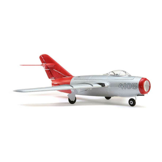
A Sport-Scale Model of the Famous Soviet-Designed Mikoyan-Gurevich MiG-15
INSTRUCTIONS FOR FINAL ASSEMBLY
The Wattage MiG-15 EDF is distributed exclusively by
Global Hobby Distributors 18480 Bandilier Circle,
Fountain Valley, CA 92708
All contents copyright © 2002, Global Hobby
Distributors Version V1.0 October 2002
Kit Product Number 128342
IMPORTANT
The Wattage MiG-15 EDF is not intended for inexperienced pilots. It is in no way a trainer. If you are
not comfortable flying low-wing sport models, we strongly suggest returning the MiG-15 EDF (brand new, in the box
with all original packaging) to the place of purchase. If you are comfortable flying low-wing sport aircraft, and even if
this is your first EDF, you should find the Wattage MiG-15 EDF a pleasure to fly.
Need help or have any questions? Call us at 1-714-963-0329 or send us an Email at service@globalhobby.net
Specifications:
Wing Span: 29.5 Inches
Wing Area: 163 Square Inches
Length: 28 Inches
Weight RTF: 19 Ounces
Functions: Ailerons, Elevator & Throttle (Steering Optional)
Power: Modified 380 Motor w/6 Blade Powerfan 400
Radio Required: 4Ch Micro w/3 Micro Servos (4 w/Optional Steering)
ESC Required: 15-30 AMP Depending on Number of Servos Used
Battery Required: 10C 1100Mah 2/3A NiMH or 10C 500Mah 2/3AR
1
Advertisement
Table of Contents

Related Manuals for WattAge MiG-15 EDF


Summary of Contents for WattAge MiG-15 EDF
- Page 1 Battery Required: 10C 1100Mah 2/3A NiMH or 10C 500Mah 2/3AR IMPORTANT The Wattage MiG-15 EDF is not intended for inexperienced pilots. It is in no way a trainer. If you are not comfortable flying low-wing sport models, we strongly suggest returning the MiG-15 EDF (brand new, in the box with all original packaging) to the place of purchase.
-
Page 2: Table Of Contents
In no case shall Wattage's liability exceed the original cost of the purchased kit. In that Wattage has no control over the final assembly or material used for final assembly, no liability shall be assumed for any damage resulting from the use by the user of the final user-assembled product. -
Page 3: Introduction
INTRODUCTION Thank you for purchasing the new Wattage MiG-15 EDF. Before completing the final assembly of your new airplane, please carefully read through this instruction manual in its entirety. Doing so will ensure your success the first time around! Wattage MiG-15 EDF Special Features:... -
Page 4: Section 1: Our Recommendations
ESC. Also, some 15 - 20 Amp ESCs don't support the use of more than three servos. If you choose to install the optional nose gear steering on your MiG-15 EDF, you will then be using four servos. Check the specifications of the ESC you choose to make sure it will support the use of four servos. - Page 5 OUR RECOMMENDATIONS, CONTINUED..We've provided some special tips for you to keep in mind when assembling your MiG-15 EDF. These tips are provided to make your flights with your MiG-15 EDF successful. Please don't overlook this valuable information. If you don't follow these special tips, we can't guarantee your success.
-
Page 6: Section 2: Tools And Supplies Required
Hitec crystal. SECTION 2: TOOLS AND SUPPLIES REQUIRED The tools and supplies listed below will be necessary to finish the assembly of your MiG-15 EDF. We suggest having these items onhand before beginning assembly. Kwik Bond 5 Minute Epoxy # 887560... -
Page 7: Section 3: Kit Contents
WARNING The MiG-15 EDF is constructed of foam. It is very important that you use no solvents, Cyanoacrylate (C/A) glue, or paint that can damage foam. If any of these chemicals comes in contact with the foam parts, the parts will be destroyed and will not be covered under warranty. -
Page 8: Section 4: Motor & Edf Fan Unit Assembly
SECTION 4: MOTOR & EDF FAN UNIT ASSEMBLY YOU'LL NEED THE FOLLOWING PARTS FROM THE KIT: (1) Impeller Nut (1) 380 Modified Motor (1) Ducted Fan Shroud (2) M2 x 4 Machine Screws (3) Noise-Suppression Capacitors (1) Impeller Fan (1) Threaded Shaft Adapter w/Set Screw YOU'LL NEED THE FOLLOWING TOOLS AND SUPPLIES: Pacer Z-42 Threadlocker 220 Grit Sandpaper w/Sanding Block... -
Page 9: Section 5: Fuselage Assembly
Carefully examine the fan shroud for any mold flashing. If any is present, carefully cut it away using a modeling knife. Slide the motor into the fan shroud and line up the holes in the front of the motor with the matching holes in the shroud. Install and tighten the two M2 x 4 machine screws to secure the motor into place. - Page 10 Using a modeling knife, carefully cut a groove in the inside of the right fuselage half, 2-1/2" behind the front of the cockpit cutout, from the base of the cockpit area to the top of the battery area in the bottom of the fuselage. The groove should be deep enough for the battery wires you plan on using to lay flush with the surface of the intake duct.
- Page 11 Special Tip: Hold the fuselage halves firmly together around the fan assembly. While holding the fuselage halves together, carefully spin the impeller using your finger. The impeller should spin freely and not touch the sides of the shroud. If the impeller does touch the sides of the shroud, the shroud may be distorted. If this is the case release some pressure on the fuselage halves and recheck the impeller.
-
Page 12: Section 6: Wing Panel Installation
Slide the motor wires and the servo extension lead through the hole and test-fit the radio tray into the fuselage. The tray should fit tightly and the lip around the edge of the tray should be pushed down firmly against the top of the fuselage. You may need to sand the inside edges of the fuselage lightly, using 220 grit sandpaper, so that the radio tray will fit properly. - Page 13 Step 2: Cutting Out the Aileron Servo Mounting Holes Using a ruler and a pencil, measure back 1-3/8" from the leading edge of one wing panel (at the root) and draw a mark on the bottom of the wing at this location. This mark shows the distance the servo's output shaft should be located behind the leading edge of the wing.
- Page 14 Using a modeling knife, very carefully cut a thin slot through the wing mounting platform, between the two marks you drew, being careful to make the cut along the bottom edge of the wing mounting platform. IMPORTANT Be careful to make the cut straight into the wing mounting platform.
-
Page 15: Section 7: Horizontal & Vertical Stabilizer Installation
While holding the wing panel aligned, turn the assembly over and carefully trace around the edges of the fiberglass wing joiner plate using a pencil. Remove the wing panel and lightly sand the surface of the wing inside the outline you drew to remove the paint. Also lightly sand the gluing surface of the fiberglass wing joiner plate. - Page 16 Using a ruler and a modeling knife, make a second cut through the elevator 1/8" out from the first cut, then carefully remove this section. You will be left with a 1/8" gap between the elevator and stabilizer, as shown. IMPORTANT Do not cut in toward the root section of the stabilizer.
- Page 17 We suggest applying a strip of clear plastic tape over the top of each elevator hinge line. This will strengthen the elevator hinge lines, especially over time. Using a modeling knife, trim the loose ends of the plastic tape even with the ends of the stabilizer panels. To install the prebent elevator joiner wire, first deflect one elevator up at a 90º...
- Page 18 After the epoxy fully cures, carefully glue back into place the two stabilizer pieces that you cut off previously. Again, make sure not to get any epoxy on the elevator joiner wire and make sure that the two pieces are flat when you glue them into place.
- Page 19 Remove the horizontal stabilizer and lightly sand the area between the lines you drew to remove as much paint from the area as possible. Mix a small quantity of 5 minute epoxy and apply a generous amount between the lines you drew on the top and bottom of the stabilizer only.
-
Page 20: Section 8: Control Systems Installation
SECTION 8: CONTROL SYSTEMS INSTALLATION YOU'LL NEED THE FOLLOWING PARTS FROM THE KIT: (3) Nylon Clevises (1) Prepainted Tape Strip (1) Prepainted Servo Mounting Board (3) Nylon Control Horns (3) Nylon Control Horn Backplates (1) Prepainted Servo Mounting Board - 2 Parts (3) M1.5 x 150 Threaded Wires YOU'LL NEED THE FOLLOWING TOOLS AND SUPPLIES: # 0 Phillips Head Screwdriver... - Page 21 Carefully push the aileron servo wire through the tunnel you cut in the servo mounting hole and out through the base of the groove you cut in the side of the fuselage. When pulling the wire up through the groove, be careful not to tear the top of the wing.
- Page 22 Step 2: Installing the Elevator Servo Install the elevator servo mounting board and elevator servo to the vertical stabilizer using the same techniques as used when installing the aileron servos. The servo should be installed on the left side of the vertical stabilizer and the servo output shaft should be toward the front of the airplane.
- Page 23 Special Tip: Before the next procedure, follow this tip to make it easier to install the control horn backplate: because the aileron is thick, we cut a shallow recess in the bottom of the aileron (the same size as the control horn backplate) so that the backplate could be attached firmly without crushing the foam.
-
Page 24: Section 9: Esc & Receiver Installation
Attach the servo horn to the Z-Bend, then attach the servo horn to the servo, making sure it's centered. The pushrod should be toward the top of the servo arm, as shown. Install and tighten the servo horn retaining screw, provided with your servo, to secure the servo horn into place. - Page 25 Carefully solder the positive and negative motor wires to your ESC, being careful that the polarity is correct. Make sure to use heat-shrink tubing to insulate the solder joints. Important Tip: We strongly suggest removing the motor plugs that are likely preinstalled on your ESC and soldering the motor wires directly to the motor wires on your ESC.
-
Page 26: Section 10: Canopy & Nose Cone Installation
SECTION 10: CANOPY & NOSE CONE INSTALLATION YOU'LL NEED THE FOLLOWING PARTS FROM THE KIT: (1) Clear Canopy (2) Prepainted Canopy Mounting Board (1) Nose Cone (2) M2 x 5 Wood Screws YOU'LL NEED THE FOLLOWING TOOLS AND SUPPLIES: # 0 Phillips Head Screwdriver Paper Towels Excel Modeling Knife Rubbing Alcohol... -
Page 27: Section 11: Flight Battery Installation
Test-fit the nose cone onto the fuselage, making sure it's centered and follows the contour of the fuselage. Notice that the nose cone and the front of the fuselage are not round. Rotate the nose cone until it fits properly without any distortion. - Page 28 Using a modeling knife, carefully cut one hole in the front and one in the back of the battery tray. These holes serve several purposes: they allow the battery to sit lower in the tray, they allow air to pass through the tray to cool the battery, and they allow a space for the battery wires from the ESC to enter the battery tray.
- Page 29 Test-fit the battery tray into the fuselage. The tray should fit tightly and the lip around the edge of the tray should be pushed down firmly against the fuselage. The battery tray is curved to match the contour of the fuselage.
- Page 30 This completes the assembly of the Wattage MiG-15 EDF. At this time you should apply the decals and decide if you want to install the optional landing gear assembly and steerable nose gear. This section is detailed beginning on the next page.
-
Page 31: Section 12: Optional Landing Gear Installation
SECTION 12: OPTIONAL LANDING GEAR INSTALLATION YOU'LL NEED THE FOLLOWING PARTS FROM THE KIT: (3) Lightweight Wheels (1) Nose Gear Bushing Assembly (1) Nose Gear Steering Arm Assembly w/Set Screw (2) Main Gear Wire Struts (1) Nose Gear Wire Strut (4) Wheel Collars w/Set Screws (4) M3 x 8 Wood Screws (2) Nylon Main Gear Mounting Plates... - Page 32 Using a 1/16" diameter drill bit, drill one pilot hole through each side of both nylon mounting plates to accept the four M2 x 5 wood screws. Again, be careful not to drill through the top of the wing. Install and tighten two M2 x 5 wood screws in each nylon mounting plate.
- Page 33 After drilling the hole through the fuselage, remove the plywood mounting plate and install the nose gear bushing assembly to it, using the flat washer and hex nut included. Tighten the hex nut securely to hold the assembly firmly to the mounting plate. Test-fit the mounting plate assembly into the recess you cut in the fuselage.
- Page 34 Step 3: Installing the Steering Servo & Linkage Using a piece of double-sided tape, mount your steering servo to the side of the battery tray, keeping it as far down and forward in the tray as possible. Make sure that the servo output shaft is toward the back of the servo tray, as shown.
-
Page 35: Section 13: Balancing The Mig-15 Edf
SECTION 14: CONTROL THROWS We recommend setting up the MiG-15 EDF using the control throws listed below. These control throws are suggested for initial test-flying because they will allow the airplane to fly smoother and make it easier to control. -
Page 36: Section 15: Preflight Check & Safety
Once you're familiar with the flight characteristics of the airplane, you might want to increase the control throws to the sport- flying settings listed below. These control throws will make the airplane more responsive and allow you to do basic aerobatics with ease. -
Page 37: Section 16: Flying The Mig-15 Edf
READ THIS BEFORE FLYING YOUR MiG-15 EDF FOR THE FIRST TIME Before flying your MiG-15 EDF for the first time, please refer back to page # 5 and re-read the special tips we've provided you. All of these tips are important, but the most important tips are the fourth one about topping off your flight battery before every flight and the last one about getting used to the fact that this is not a propeller-driven aircraft, so it will behave differently in the air. -
Page 38: Section 17: Replacement Parts
We suggest ordering directly from your local dealer. If your dealer does not stock Wattage products, you can order directly from us at the address shown below:... -
Page 39: Product Evaluation Sheet
Global Hobby Distributors will not disclose the information it collects to outside parties. Global Hobby Distributors does not sell, trade, or rent your personal information to others. Your privacy is important to us. 128342 Kit: Wattage MiG-15 EDF # Was any of the assembly difficult for you? If yes, please explain. - Page 40 _____________________________ _____________________________ Post Office will not deliver _____________________________ without proper postage (Return Address Here) Global Hobby Distributors Attn: Global Services 18480 Bandilier Circle Fountain Valley CA 92728-8610 Fold along dotted line Visit our website at http://watt-age.globalhobby.com or for Customer Service at http://globalservices.globalhobby.com...
Need help?
Do you have a question about the MiG-15 EDF and is the answer not in the manual?
Questions and answers