Table of Contents
Advertisement
Quick Links
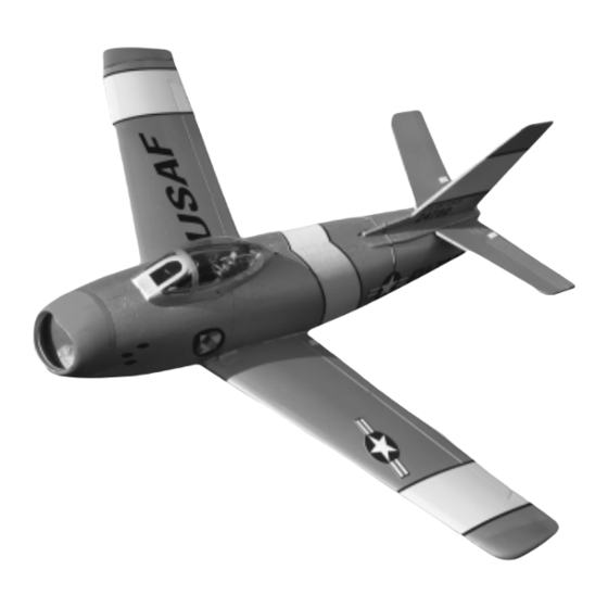
INSTRUCTIONS FOR FINAL ASSEMBLY
Specifications:
Wing Span: 29.5 Inches
Wing Area: 162.75 Square Inches
Length: 26 Inches
Weight RTF: 19.25 - 21 Ounces
Functions: Ailerons, Elevator (Elevons) and Throttle
Product Part Number 128380
Power: Modified 380 Motor w/6 Blade Power Fan 400
Radio: 4 Channel Micro w/2 Servos and Elevon Mixing
The Wattage F-86 Sabre EDF is distributed exclusively by Global Hobby Distributors 18480 Bandilier Circle, Fountain Valley, CA 92708
All contents copyright © 2002, Global Hobby Distributors Version V1.0 April 2002
1
Visit our website at http://watt-age.globalhobby.com for information on other Wattage products
Advertisement
Table of Contents

Related Manuals for WattAge F-86 Sabre EDF


Summary of Contents for WattAge F-86 Sabre EDF
-
Page 1: Specifications
Radio: 4 Channel Micro w/2 Servos and Elevon Mixing The Wattage F-86 Sabre EDF is distributed exclusively by Global Hobby Distributors 18480 Bandilier Circle, Fountain Valley, CA 92708 All contents copyright © 2002, Global Hobby Distributors Version V1.0 April 2002... -
Page 2: Table Of Contents
In no case shall Wattage's liability exceed the original cost of the purchased kit. In that Wattage has no control over the final assembly or material used for final assembly, no liability shall be assumed for any damage resulting from the use by the user of the final user-assembled product. -
Page 3: Introduction
INTRODUCTION Thank you for purchasing the new Wattage F-86 Sabre EDF. Before completing the final assembly of your new airplane, please carefully read through this instruction manual in its entirety. Doing so will ensure your success the first time around! -
Page 4: Section 1: Our Recommendations
SECTION 1: OUR RECOMMENDATIONS This section describes the items you will need to purchase for your new F-86 Sabre EDF. These suggestions are not set in stone, but they should provide you with a good starting point. IMPORTANT When choosing accessories for your F-86, such as servos, ESC, and receiver, it's very important to take the weight of these items into consideration. -
Page 5: Section 2: Tools And Supplies Required
Wattage 14 Gauge Hi-Temp Silicon Wire IMPORTANT The part numbers listed for the Hitec receiver, Cirrus servos, Cirrus servo extensions, Cirrus Elevon Mixer and Wattage ESC are compatible with Hitec and JR (receiver is compatible with Hitec only) radio control systems. These items are also available with connectors that are compatible with Futaba and Airtronics radio control systems. -
Page 6: Section 3: Kit Contents
(2) 2.5 x 10mm Wood Screws WARNING (3) Nylon Wing Skid Mounting Plates The F-86 Sabre EDF is constructed of foam. It is very important (3) Prebent Wing Skid Wires that you use no solvents, Cyanoacrylate (C/A) glue, or paint (2) Brass Pins that can damage foam. -
Page 7: Section 4: Motor Break-In
The terminal with the red dot next to it is the positive terminal. IMPORTANT The wires must be 18" long to reach the cockpit area and still have some extra left to work with. Visit our website at http://watt-age.globalhobby.com for information on other Wattage products... - Page 8 Step 2: Installing the Impeller Before the impeller is installed and run for the first time, you should check the impeller's balance. Usually our impellers will not need balancing, but it's a good idea to check. We suggest using a propeller balancer to do this. If the impeller is out-of-balance, apply a small piece of electrical tape to the back side of the "light blade."...
-
Page 9: Section 5: Ducted Fan Assembly
Very carefully push a small piece of wire between the impeller blades and into the motor (not far in) to prevent the motor from turning while tightening the impeller nut. Visit our website at http://watt-age.globalhobby.com for information on other Wattage products... -
Page 10: Section 6: Fuselage Assembly
SECTION 6: FUSELAGE ASSEMBLY YOU'LL NEED THE FOLLOWING PARTS: (1) Left & Right Fuselage Halves (1) Radio Tray YOU'LL NEED THE FOLLOWING TOOLS AND SUPPLIES: Kwik Bond 5 Minute Epoxy Paper Towels Excel Modeling Knife Rubbing Alcohol Scissors NHP Epoxy Mixing Sticks 220 Grit Sandpaper w/Sanding Block NHP Epoxy Mixing Cups Step 1: Test-Fitting the Ducted Fan Assembly... - Page 11 Using a pair of scissors, cut away the excess plastic from around the edge of the radio tray, making sure to leave a 1/8" lip to use as a mounting surface. Visit our website at http://watt-age.globalhobby.com for information on other Wattage products...
- Page 12 Using 220 grit sandpaper with a sanding block, sand the edges of the radio tray smooth and even. Using a modeling knife, carefully cut a small hole in the back of the radio tray big enough to allow the motor wires to pass through.
-
Page 13: Section 7: Wing Panel Assembly & Installation
Working with one wing panel for now, use a modeling knife and a ruler to carefully cut out the outer end of the aileron along the molded scribe line. Visit our website at http://watt-age.globalhobby.com for information on other Wattage products... - Page 14 Using a modeling knife and a ruler, carefully cut 1/16" off of the inboard section of the aileron. Cutting the inboard section of the aileron shorter will prevent the aileron from hitting the side of the fuselage when the wing panel is glued into place. Carefully flex the aileron up and down several times to free up the hinge line.
- Page 15 Fit the wing panel back into place and realign it. Remove any excess epoxy using a paper towel and rubbing alcohol, and hold the wing panel firmly in place until the epoxy sets up. Repeat the previous procedures to install the second wing panel. Visit our website at http://watt-age.globalhobby.com for information on other Wattage products...
-
Page 16: Section 8: Horizontal Stabilizer Installation
SECTION 8: HORIZONTAL STABILIZER INSTALLATION YOU'LL NEED THE FOLLOWING PARTS: (2) 1.5mm x 400mm Threaded Wires (1) Left & Right Horizontal Stabilizer Panels YOU'LL NEED THE FOLLOWING TOOLS AND SUPPLIES: Kwik Bond 5 Minute Epoxy 220 Grit Sandpaper w/Sanding Block Wire Cutters Paper Towels Excel Modeling Knife... - Page 17 Repeat the previous procedures to align and install the second stabilizer panel on the other side of the fuselage. Visit our website at http://watt-age.globalhobby.com for information on other Wattage products...
-
Page 18: Section 9: Control Systems Installation
SECTION 9: CONTROL SYSTEMS INSTALLATION YOU'LL NEED THE FOLLOWING PARTS: (2) Nylon Control Horns - w/Predrilled Holes (2) Fuselage Tape (4) Nylon Control Horn Backplates (2) 1.5mm x 150mm Threaded Wires (4) Nylon Clevises (2) 1.5mm x 400mm Threaded Wires (2) Nylon Control Horns - Plain YOU'LL NEED THE FOLLOWING TOOLS AND SUPPLIES: Wilhold Silicon Sealant... - Page 19 Reinstall the individual servo wires into the plastic plug (if you removed it earlier) and push the plug through the hole and into the radio compartment. The servo wire should lay in the molded channel. Visit our website at http://watt-age.globalhobby.com for information on other Wattage products...
- Page 20 Carefully remove the protective backing from one piece of fuselage tape. With the servo wire completely in the molded channel, apply the tape to the fuselage side, making sure to cover the entire length of the molded channel from the top of the wing to the base of the radio compartment.
- Page 21 1/4" out from the center of the servo horn. If you're using Cirrus CS-10 servos this will be the first hole in the servo arm. Visit our website at http://watt-age.globalhobby.com for information on other Wattage products...
- Page 22 Using Z-Bend pliers, make a Z-Bend in the pushrod wire at the mark you drew. Cut away the excess wire using a pair of wire cutters, making sure to leave about 1/8" of wire beyond the Z-Bend. Remove the servo horn from the servo. Using a 1/16" drill bit, enlarge the hole in the servo arm that is 1/4" out from the center of the servo horn.
-
Page 23: Section 10: Esc & Receiver Installation
The wires should be at least 5" long from the ESC to the plug. To minimize current loss, we also suggest using a Dean's Plug instead of the stock Tamiya connector that's likely preinstalled on your ESC. Visit our website at http://watt-age.globalhobby.com for information on other Wattage products... - Page 24 Carefully solder the motor wires to your ESC, being careful that the polarity is correct. Make sure to use heat shrink tubing to insulate the solder joints. Secure the ESC as far forward as possible to the base of the radio tray using a small piece of double-sided tape. Orientate the ESC so the battery wires are toward the back of the airplane.
-
Page 25: Section 11: Canopy & Nose Cone Installation
One piece goes on each side of the fuselage as shown. Use a modeling knife to cut away the portion of mounting board that sticks up past the top of the fuselage. Visit our website at http://watt-age.globalhobby.com for information on other Wattage products... - Page 26 Set the canopy into place and align it. When satisfied with the alignment, install and tighten two 2mm x 5mm wood screws, threaded through the canopy and into the mounting board, to hold the canopy in place. Use the tip of your modeling knife to make small pilot holes in the canopy and mounting board.
-
Page 27: Section 12: Flight Battery Installation
It's easier to cut the holes to the right size now then after the battery tray is glued into place. Visit our website at http://watt-age.globalhobby.com for information on other Wattage products... - Page 28 Carefully push the two brass pins through the front of the battery tray as shown. Space the pins equally apart and make sure that they are even with each other. Making a small pilot hole in the battery tray with the tip of your modeling knife will make it easier to push the pins into place.
- Page 29 The holes should only be large enough to slide over the two brass pins. Using a pair of scissors, cut out a 1/2" square piece of plastic left over from cutting out the battery cover. Visit our website at http://watt-age.globalhobby.com for information on other Wattage products...
-
Page 30: Section 13: Final Assembly
Carefully glue the piece of 1/2" square plastic (painted side up) to the top back of the battery cover, using a thin layer of 5 minute epoxy. The plastic piece should be centered and overhang the back edge of the battery cover by 1/4". IMPORTANT Don't forget to roughen the gluing surfaces using 220 grit sandpaper so that the epoxy sticks better to the plastic. - Page 31 If you ever want to remove the wing skids after the mounts have been glued to the airplane, you can simply squeeze the prebent loop together and pull the skids from the mounts. Visit our website at http://watt-age.globalhobby.com for information on other Wattage products...
- Page 32 Set one wing skid assembly onto the bottom of one wing panel. To align the assembly properly, the inside edge of the mounting plate should be 1-1/4" out from the wing glue joint and the back edge of the mounting plate should be 1/2" in front of the aileron hinge line.
-
Page 33: Section 14: Balancing The F-86 Sabre Edf
C.G. back until you are comfortable with the flight characteristics of the airplane. Balance the F-86 Sabre EDF with the flight battery installed. Measure and draw two marks on the top of the wing, 3-1/8" back from the leading edge, at the glue joints. -
Page 34: Section 15: Control Throws
SECTION 15: CONTROL THROWS We recommend setting up the F-86 Sabre EDF using the control throws listed below. These control throws are suggested for initial test-flying because they will allow the airplane to fly smoother and make it easier to control. -
Page 35: Section 17: Flying The F-86 Sabre Edf
Check every glue joint in the F-86 Sabre EDF to ensure that everything is tight and well-bonded. Double-check the balance of the airplane. Do this with the flight battery installed. Check the control surfaces. They should move in the correct direction and not bind. -
Page 36: Section 18: Replacement Parts
In the Air In the air the F-86 Sabre EDF is smooth, predictable and rock-steady. At full power, the airplane is fast and responsive to control inputs, and handles light winds with ease. Loops, rolls, Immelmann turns, cuban eights and other aerobatics are completed without much effort. -
Page 37: Section 10: Stabilizer Alignment Template
Using a pencil, trace the template onto a piece of cardstock. The box your kit came in works great for this. Using a pair of scissors, carefully cut out the template from the cardstock. Visit our website at http://watt-age.globalhobby.com for information on other Wattage products... - Page 38 Need help or have any questions? Call us at 1-714-963-0329 or send us an E-mail to service@globalhobby.net...
-
Page 39: Product Evaluation Sheet
2 - 4 5 - 7 8 - 10 10 or More Please List any Other Modeling Interests or any Additional Information about This Product: ______________________ _____________________________________________________________________________________ _____________________________________________________________________________________ _____________________________________________________________________________________ _____________________________________________________________________________________ Visit our website at http://watt-age.globalhobby.com for information on other Wattage products... - Page 40 _____________________________ _____________________________ Post Office will not deliver _____________________________ without proper postage (Return Address Here) Global Hobby Distributors Attn: Customer Service 18480 Bandilier Circle Fountain Valley CA 92728-8610 Fold along dotted line Need help or have any questions? Call us at 1-714-963-0329 or send us an E-mail to service@globalhobby.net...
Need help?
Do you have a question about the F-86 Sabre EDF and is the answer not in the manual?
Questions and answers