Table of Contents
Advertisement
Quick Links
INSTRUCTIONS FOR FINAL ASSEMBLY
The Wattage Cap 232 EP ARF is distributed
exclusively by Global Hobby Distributors 18480
Bandilier Circle, Fountain Valley, CA 92708
All contents copyright © 2002, Global Hobby
Distributors Version V3.0 June 2002
Kit Product Number 128407
Visit our website at http://watt-age.globalhobby.com for information on other Wattage products
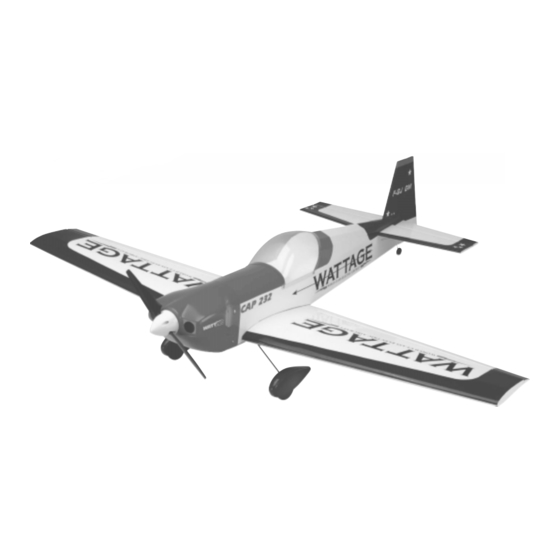
Specifications:
Wing Span: 36 Inches
Wing Area: 220 Square Inches
Length: 32 Inches
Weight RTF: 26 - 30 Ounces
Functions: Ailerons, Elevator, Rudder and Throttle
Power: Cobalt 400 Direct Drive w/7 x 4 Propeller
Radio: 4 Channel Micro w/3 Micro Servos & 30 AMP ESC
1
Advertisement
Table of Contents

Related Manuals for WattAge Cap 232 EP


Summary of Contents for WattAge Cap 232 EP
-
Page 1: Specifications
Power: Cobalt 400 Direct Drive w/7 x 4 Propeller Radio: 4 Channel Micro w/3 Micro Servos & 30 AMP ESC All contents copyright © 2002, Global Hobby Distributors Version V3.0 June 2002 Kit Product Number 128407 Visit our website at http://watt-age.globalhobby.com for information on other Wattage products... -
Page 2: Table Of Contents
In no case shall Wattage's liability exceed the original cost of the purchased kit. In that Wattage has no control over the final assembly or material used for final assembly, no liability shall be assumed for any damage resulting from the use by the user of the final user-assembled product. -
Page 3: Introduction
INTRODUCTION Thank you for purchasing the new Wattage Cap 232 EP. Before completing the final assembly of your new airplane, please carefully read through this instruction manual in its entirety. Doing so will ensure your success the first time around! -
Page 4: Section 1: Our Recommendations
SECTION 1: OUR RECOMMENDATIONS This section describes the items you will need to purchase for your new Cap 232 EP. These suggestions are not set in stone, but they should provide you with a good starting point. IMPORTANT When choosing accessories for your Cap 232, such as servos, ESC, and receiver, it's very important to take the weight of these items into consideration. -
Page 5: Section 2: Kit Contents
609.6mm 1/16" 1.6mm 3/8" 9.5mm 3" 76.2mm 30" 762.0mm 3/32" 2.4mm 1/2" 12.7mm 6" 152.4mm 36" 914.4mm 1/8" 3.2mm 5/8" 15.9mm 12" 304.8mm 5/32" 4.0mm 3/4" 19.0mm 18" 457.2mm Visit our website at http://watt-age.globalhobby.com for information on other Wattage products... -
Page 6: Section 4: Tools And Supplies Required
SECTION 5: REPLACEMENT PARTS Wattage stocks a complete line of replacement parts for your Cap 232 EP. Listed below are the replacement parts that are available along with their respective part numbers for easy ordering convenience. We suggest ordering directly from your local dealer. -
Page 7: Section 6: A Note About Covering
SECTION 7: BECOMING FAMILIAR WITH YOUR COBALT 400 MOTOR Your Wattage Cap 232 EP is powered by the Wattage Super Cobalt 400 Direct Drive motor. This motor is a high-quality alternative to lower power, closed end-bell motors, and more expensive specialty motors. The Super Cobalt 400 Direct Drive motor features a 3.2mm (1/8") shaft and a bolt pattern that can match either 05 or 400 size mounting dimensions. - Page 8 Step 1: Breaking In the Motor Motor break-in is not absolutely necessary, but taking time to break in the motor now will result in increased motor performance and longevity. You can either leave the motor secured to the fuselage during the break-in process or you can remove the motor and secure it to a test stand.
-
Page 9: Section 8: Mounting The Wing
Visit our website at http://watt-age.globalhobby.com for information on other Wattage products... -
Page 10: Section 9: Horizontal Stabilizer
Secure the wing into place using the 3mm x 20mm flange-head machine screw. Don't overtighten the screw. You don't want to crush the wing or distort the trailing edge. SECTION 9: HORIZONTAL STABILIZER YOU'LL NEED THE FOLLOWING PARTS: (1) Horizontal Stabilizer w/Elevator & Hinges YOU'LL NEED THE FOLLOWING TOOLS AND SUPPLIES: Kwik Bond 5 Minute Epoxy Masking Tape... - Page 11 When you are satisfied that the stabilizer is aligned, use a pencil to draw a couple of marks on each side of the stabilizer where it and the fuselage sides meet, then use a couple of pieces of masking tape to hold the stabilizer firmly in place. Visit our website at http://watt-age.globalhobby.com for information on other Wattage products...
-
Page 12: Section 10: Vertical Stabilizer
With the stabilizer held firmly in place, look from the front of the airplane at both the wing and the stabilizer. When aligned properly, the stabilizer should be parallel to the wing. C=C-1 IMPORTANT If the stabilizer is out of alignment, remove it and use 220 grit sandpaper with a sanding block to sand down the higher side of the stabilizer mounting platform, then reinstall the stabilizer and check the alignment once more. - Page 13 Push the stabilizer into place and realign it, double-checking all of your measurements once more before the epoxy sets up. Quickly remove any excess epoxy and hold the stabilizer in place until the epoxy has set up. Visit our website at http://watt-age.globalhobby.com for information on other Wattage products...
-
Page 14: Section 11: Hinging The Control Surfaces
SECTION 11: HINGING THE CONTROL SURFACES YOU'LL NEED THE FOLLOWING PARTS: (1) Prebent Tail Wheel Wire (2) 1mm Nylon Wheel Retainers (1) Tail Wheel YOU'LL NEED THE FOLLOWING TOOLS AND SUPPLIES: Kwik Bond Thin C/A Pencil Kwik Bond 5 Minute Epoxy 220 Grit Sandpaper w/Sanding Block Kwik Bond C/A Debonder Waxed Paper... - Page 15 Using a drill with a 1/16" drill bit, carefully drill a shallow hole into the leading edge of the rudder at the mark you drew. Make sure you drill the hole perpendicular to the leading edge. Visit our website at http://watt-age.globalhobby.com for information on other Wattage products...
- Page 16 Using a modeling knife, carefully cut a shallow groove in the leading edge from the base of the hole down to the bot- tom of the rudder. Test-fit the tail wheel wire into the hole and groove. When properly aligned, the wire should rest within the groove and the outer surface of the wire should be flush with the leading edge of the rudder.
-
Page 17: Section 12: Installing The Main Landing Gear
Make sure the straps do not hang over the edge of the hatch cover. Remove the straps and drill 1/16" pilot holes into the fuselage at the locations you marked. Visit our website at http://watt-age.globalhobby.com for information on other Wattage products... - Page 18 Install the straps using four 2.5mm x 10mm wood screws. Tighten the screws completely to secure the landing gear wires into place. Step 2: Installing the Wheels & Wheel Pants Slide one wheel pant partially onto one of the landing gear axles followed by one 3mm wheel spacer. IMPORTANT If you look inside the wheel pant you will see a piece of plywood glued to the side of the pant.
-
Page 19: Section 13: Servo Installation
It should face the leading edge of the wing. Run the servo lead out of the wing through the notch in the side of the tray. Visit our website at http://watt-age.globalhobby.com for information on other Wattage products... -
Page 20: Section 14: Pushrod Installation
SECTION 14: PUSHROD INSTALLATION YOU'LL NEED THE FOLLOWING PARTS: (2) Plywood Control Horns (2) 1mm x 450mm Pushrod Wires (2) 1mm x 120mm Pushrod Wires YOU'LL NEED THE FOLLOWING TOOLS AND SUPPLIES: Kwik Bond Thick C/A Excel Modeling Knife # 0 Phillips Head Screwdriver Ernst Airplane Stand Magnum Z-Bend Pliers Ruler... - Page 21 With both the servo horn and the elevator centered, use a pencil to draw a mark on the pushrod wire where it crosses the third hole out from the center of the servo horn. Visit our website at http://watt-age.globalhobby.com for information on other Wattage products...
- Page 22 Using Magnum Z-Bend Pliers, make a Z-bend in the pushrod wire at the mark you drew. Use wire cutters to remove the excess wire. Connect the servo arm to the Z-Bend and attach the servo horn to the servo output shaft, making sure that the servo horn is centered.
- Page 23 C/A dries completely. Step 5: Installing the Servo Horn Use a couple of pieces of masking tape, taped between the vertical stabilizer and the rudder, to hold the rudder centered. Visit our website at http://watt-age.globalhobby.com for information on other Wattage products...
- Page 24 Plug the rudder servo into the receiver. Plug the ESC into the receiver and the flight battery into the ESC . Turn on the radio system and center the servo using the trim lever on the transmitter. Place a "single arm" servo horn onto the rudder servo, making sure that the servo horn is centered and points toward the fuselage side.
- Page 25 Plug the aileron servo into the receiver. Plug the ESC into the receiver and the flight battery into the ESC. Turn on the radio system and center the servo using the trim lever on the transmitter. Visit our website at http://watt-age.globalhobby.com for information on other Wattage products...
- Page 26 Place a "dual arm" servo horn onto the aileron servo, making sure that the servo horn is centered. Each of the arms should have at least five holes in it. Use a couple of pieces of masking tape, taped between the wing and the ailerons, to hold the ailerons centered. With both the servo horn and the ailerons centered, use a pencil to draw a mark on each pushrod wire where it crosses the fourth hole out from the center of the servo horn.
-
Page 27: Section 15: Final Assembly
Slide the plastic spinner cone over the propeller and align it with the molded grooves in the backplate. Secure the spinner cone in place using two 2.5mm x 10mm wood screws. IMPORTANT Be careful not to overtighten the screws. Overtightening the screws could cause the spinner to crack. Visit our website at http://watt-age.globalhobby.com for information on other Wattage products... - Page 28 Step 2: Applying the Decals Using a clean cloth, wipe the airframe down completely to remove dust, debris and oil. Cut out each of the decals and apply them using the box cover photos for reference. If any air bubbles form under the decals you can "prick" the bubbles with a pin to release the air. Step 3: Installing the Receiver Plug the elevator and rudder servo leads into their proper slots in the receiver.
- Page 29 Reinstall the hatch cover, being careful not to overtighten the screws. Step 6: Opening the Air-Exit Hole Using a modeling knife, remove the covering from over the precut air-exit hole in the bottom of the fuselage. Visit our website at http://watt-age.globalhobby.com for information on other Wattage products...
-
Page 30: Section 16: Balancing The Cap 232 Ep
This location is recommended for initial test flying. The C.G. can be moved fore or aft up to 1/4", but it is not recommended that the C.G. be located any farther back than 2-1/2". Balance the Cap 232 EP with the flight battery installed. Install the wing onto the fuselage. -
Page 31: Section 18: Control Throws
SECTION 18: CONTROL THROWS We recommend setting up the Cap 232 EP using the control throws recommended in the pushrod installation steps. Those control throws are suggested for initial test flying. If you haven't set up the control throws yet, we have listed them here again. - Page 32 Check the condition of the transmitter batteries. They should be fully charged. Check every bolt and every glue joint in the Cap 232 EP to ensure that everything is tight and well-bonded. This should include all of the control surface hinges, too.
-
Page 33: Section 20: Flying The Cap 232 Ep
In the Air In the air the Cap 232 EP is smooth and predictable. At full power, the motor and propeller combination produce enough torque to pull the airplane through just about any maneuver you want. You'll find that the airplane is responsive to control inputs and handles light winds with ease. -
Page 34: Section 21: Trim Chart
SECTION 21: TRIM CHART After you have test-flown and done the initial trim changes to the aircraft, use the Trim Chart below to begin trimming your airplane. Following and adhering to this chart will result in the ability to diagnose trim problems and correct those problems using the simple adjustments shown below. -
Page 35: Product Evaluation Sheet
2 - 4 5 - 7 8 - 10 10 or More Please List any Other Modeling Interests or any Additional Information about This Product: ______________________ _____________________________________________________________________________________ _____________________________________________________________________________________ _____________________________________________________________________________________ _____________________________________________________________________________________ Visit our website at http://watt-age.globalhobby.com for information on other Wattage products... - Page 36 _____________________________ _____________________________ Post Office will not deliver _____________________________ without proper postage (Return Address Here) Global Hobby Distributors Attn: Global Services 18480 Bandilier Circle Fountain Valley CA 92728-8610 Fold along dotted line Need help or have any questions? Call us at 1-714-963-0329 or send us an email to service@globalhobby.net...
Need help?
Do you have a question about the Cap 232 EP and is the answer not in the manual?
Questions and answers