Table of Contents
Advertisement
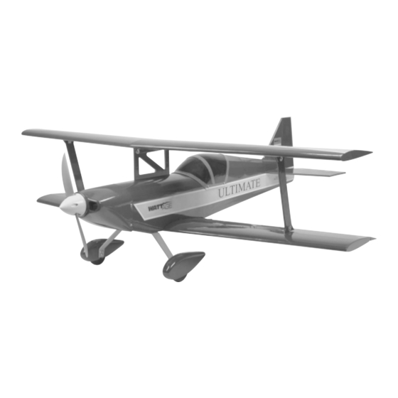
Electric-Powered Aerobatic Small-Field Flyer
Brought to You By:
INSTRUCTIONS FOR FINAL ASSEMBLY
The Wattage Ultimate Bipe EP is distributed
exclusively by Global Hobby Distributors
18480 Bandilier Circle, Fountain Valley, CA 92708
All contents copyright © 2003, Global Hobby
Distributors Version V1.0 March 2003
Kit Product Number 128401
IMPORTANT
The Wattage Ultimate Bipe EP is not intended for inexperienced pilots. It is in no way a trainer. If you
are not comfortable flying aerobatic sport aircraft, we strongly suggest returning the Ultimate Bipe EP (brand new, in
the box with all original packaging) to the place of purchase.
Visit our website at http://watt-age.globalhobby.com for information on other Wattage products
Specifications:
Wing Span: 29-7/8 Inches (Top & Bottom)
Wing Area: 300 Square Inches
Length: 30-1/2 Inches
Weight RTF: 31 - 35 Ounces
Wing Loading: 14 - 17 Ounces Per Square Inch
Functions: Ailerons, Elevator, Rudder & Throttle
Power: Cobalt 400 Direct Drive w/7 x 4 Propeller
Radio Required: 4Ch or More Micro w/3 Micro Servos
ESC Required: 30 Amp Micro
Battery Required: 7 Cell CP1300SCR
1
Advertisement
Table of Contents

Related Manuals for WattAge ULTIMATE


Summary of Contents for WattAge ULTIMATE
- Page 1 Battery Required: 7 Cell CP1300SCR IMPORTANT The Wattage Ultimate Bipe EP is not intended for inexperienced pilots. It is in no way a trainer. If you are not comfortable flying aerobatic sport aircraft, we strongly suggest returning the Ultimate Bipe EP (brand new, in the box with all original packaging) to the place of purchase.
-
Page 2: Table Of Contents
In no case shall Wattage's liability exceed the original cost of the purchased kit. In that Wattage has no control over the final assembly or material used for final assembly, no liability shall be assumed for any damage resulting from the use by the user of the final user-assembled product. -
Page 3: Introduction
INTRODUCTION Thank you for purchasing the new Wattage Ultimate Bipe EP. Before completing the final assembly of your new airplane, please carefully read through this instruction manual in its entirety. Doing so will ensure your success the first time around! -
Page 4: Section 1: Our Recommendations
This section describes our recommendations to help you in deciding which types of accessories to purchase for your new Ultimate Bipe EP. Please read through this entire section very carefully. We have provided you with tips and recommendations that, if followed, will result in a great flying airplane. Failure to follow our recommendations may result in a poor flying airplane. -
Page 5: Section 2: Tools And Supplies Required
Note that the Hitec 555 micro receiver uses a dual conversion FM Hitec crystal. SECTION 2: TOOLS AND SUPPLIES REQUIRED The tools and supplies listed below will be necessary to finish the assembly of your Ultimate Bipe EP. We suggest having these items onhand before beginning assembly. Ruler... -
Page 6: Section 3: Kit Contents
Strip (1) Decal Set We stock a complete line of replacement parts for your Wattage Ultimate Bipe EP. Please refer to page # 29 for more details and a replacement parts list. To convert inches into millimeters: Inches x 25.4 = mm To convert millimeters into inches: Millimeters / 25.4 = in... -
Page 7: Section 4: A Note About Covering
SECTION 5: BECOMING FAMILIAR WITH YOUR COBALT 400 MOTOR Your Wattage Ultimate Bipe EP is powered by the Wattage Super Cobalt 400 Direct Drive motor. This motor is a high-quality alternative to lower power, closed end-bell motors, and more expensive specialty motors. The Super Cobalt 400 Direct Drive motor features a 3.2mm (1/8") shaft and a bolt pattern that can match either 05 or 400 size mounting... -
Page 8: Section 6: Breaking In The Super Cobalt 400 Motor
SECTION 6: BREAKING IN THE SUPER COBALT 400 MOTOR Taking time to break in the motor now will result in increased motor performance and longevity. You can either leave the motor secured to the fuselage during the break-in process or you can remove the motor and secure it to a test stand. -
Page 9: Section 7: Hinging The Control Surfaces
Mix a small quantity of 5 minute epoxy. Apply a thin layer to the end of the aileron torque rod and pack more into the predrilled hole and the precut groove in the leading edge of the aileron. Visit our website at http://watt-age.globalhobby.com for information on other Wattage products... - Page 10 Slide the aileron and its hinges into the hinge slots in the trailing edge of the wing, making sure that the torque rod is firmly seated in the leading edge of the aileron. Adjust the aileron so that the tip of the aileron is even with the wing tip. While holding the aileron tightly against the wing, pivot the aileron down about 45º...
-
Page 11: Section 8: Stabilizer Installation
Set the wing into the wing saddle and secure it into place using the M4 x 20 machine screw. Visit our website at http://watt-age.globalhobby.com for information on other Wattage products... - Page 12 Using a modeling knife and a ruler, carefully cut out the section of the fuselage directly behind the horizontal stabilizer mounting slot. IMPORTANT Save the piece that you cut out. It will be glued back into place after mounting the stabilizer. Slide the stabilizer into the mounting slot and temporarily align it.
- Page 13 - two in the stabilizer and one in the fuselage. Remember, after allowing the C/A to fully cure, pull on the rudder to check the integrity of the hinges. Visit our website at http://watt-age.globalhobby.com for information on other Wattage products...
-
Page 14: Section 9: Landing Gear Installation
SECTION 9: LANDING GEAR INSTALLATION YOU'LL NEED THE FOLLOWING PARTS FROM THE KIT: (1) Aluminum Main Gear Strut (2) M3 x 25 Machine Screws (4) M3 Hex Nuts (2) Wheel Pants (2) Main Gear Wheels (2) M3 Lock Nuts (4) M2 x 5 Wood Screws (2) M3 x 10 Wood Screws YOU'LL NEED THE FOLLOWING TOOLS AND SUPPLIES: Kwik Bond Thin C/A... -
Page 15: Section 10: Control Systems Installation
Depending on the particular servo you're using, you may need to enlarge the holes slightly. IMPORTANT The elevator servo is installed in the left side of the servo tray, as shown. Visit our website at http://watt-age.globalhobby.com for information on other Wattage products... - Page 16 Slide one nylon pushrod snap-link onto one 17-3/4" long pushrod wire, then make an L-Bend in the very end of the wire, using needle nose pliers. Using a pair of needle nose pliers, carefully bend a "V" shape in the wire, as shown. The middle of the "V" should be 7/8"...
- Page 17 Install your rudder servo into the servo tray, making sure that the servo output shaft is toward the front of the fuselage. Visit our website at http://watt-age.globalhobby.com for information on other Wattage products...
- Page 18 Slide the remaining nylon pushrod snap-link onto the remaining 17-3/4" long pushrod wire and carefully make an L-Bend and a "V" shaped bend in the pushrod wire. For this pushrod though, the "V" shaped bend should be made away from the L-Bend, as shown. Insert the L-Bend into the outermost hole in the remaining nylon control horn so that the longer portion of the pushrod wire is toward the left side of the control horn, and hook the...
- Page 19 Remove the masking tape from the ailerons and center them by using a pair of pliers to carefully open or close the "V" in each pushrod wire. Visit our website at http://watt-age.globalhobby.com for information on other Wattage products...
- Page 20 Step 4: Installing the Receiver The locations of the radio equipment shown in the next few steps is only approximate. This is how our test airplanes were set up. The locations of your radio equipment could differ and should be dependent on what type of equipment you use and where you balance your airplane.
-
Page 21: Section 11: Top Wing & Strut Installation
Mount the bottom wing to the fuselage using the M3 x 20 machine screw provided. Visit our website at http://watt-age.globalhobby.com for information on other Wattage products... -
Page 22: Section 12: Final Assembly
Carefully mount the top wing to the center cabane strut using two M3 x 8 machine screws. IMPORTANT Make sure to use the two M3 x 8 machine screws and not two M3 x 6 machine screws. Airplane pictured upside down for photo clarity. Mount the two outer wing struts to the mounting brackets using four M3 x 6 machine screws. - Page 23 This hot air must exit the fuselage to prevent the motor, ESC and flight battery from overheating. Do not omit this procedure. Visit our website at http://watt-age.globalhobby.com for information on other Wattage products...
-
Page 24: Section 13: Balancing The Ultimate Bipe Ep
C/G back until you are comfortable with the flight characteristics of the airplane. Balance the Ultimate Bipe EP with the flight battery installed. Measure and draw two marks on the bottom of the TOP wing, 2-3/4" back from the leading edge, measured at the centerline of the wing. -
Page 25: Section 15: Control Throws
SECTION 15: CONTROL THROWS We recommend setting up the Ultimate Bipe EP using the control throws listed below. These control throws are suggested for initial test-flying because they will allow the airplane to fly smoother and make it easier to control. - Page 26 PREFLIGHT CHECK & SAFETY CONTINUED..Check the condition of the transmitter batteries. They should be fully charged. Check every bolt and every glue joint in the airplane to ensure that everything is tight and well-bonded. Double-check that all of the control horns are tight. Double-check the balance of the airplane.
-
Page 27: Section 17: Flying The Ultimate Bipe Ep
SECTION 17: FLYING THE ULTIMATE BIPE EP The Ultimate Bipe EP is designed for those pilots who are experienced at flying sport models. It is not a trainer. If you do not feel comfortable about test-flying the airplane, don't hesitate to ask someone more experienced for help. -
Page 28: Section 18: Ultimate Bipe Ep Trimming Chart
SECTION 18: ULTIMATE BIPE EP TRIMMING CHART After you have test-flown and done the initial trim changes to the airplane, use this trimming chart to begin trimming your airplane. Following and adhering to this chart will result in the ability to diagnose trim problems and correct those problems using the simple adjustments shown below. -
Page 29: Section 19: Replacement Parts
We suggest ordering directly from your local dealer. If your dealer does not stock Wattage products, you can order directly from us at the address shown below:... - Page 30 Need help or have any questions? Call us at 1-714-963-0329 or send us an email to service@globalhobby.net...
-
Page 31: Product Evaluation Sheet
2 - 4 5 - 7 8 - 10 10 or More Please List any Other Modeling Interests or any Additional Information about This Product: ______________________ _____________________________________________________________________________________ _____________________________________________________________________________________ _____________________________________________________________________________________ _____________________________________________________________________________________ Visit our website at http://watt-age.globalhobby.com for information on other Wattage products... - Page 32 _____________________________ _____________________________ Post Office will not deliver _____________________________ without proper postage (Return Address Here) Global Hobby Distributors Attn: Global Services 18480 Bandilier Circle Fountain Valley CA 92728-8610 Fold along dotted line Need help or have any questions? Call us at 1-714-963-0329 or send us an email to service@globalhobby.net...
Need help?
Do you have a question about the ULTIMATE and is the answer not in the manual?
Questions and answers